Week 4: Electronics Production
Assignment: Make an in circuit programmer. We are using cirqoid for the milling.

Design:
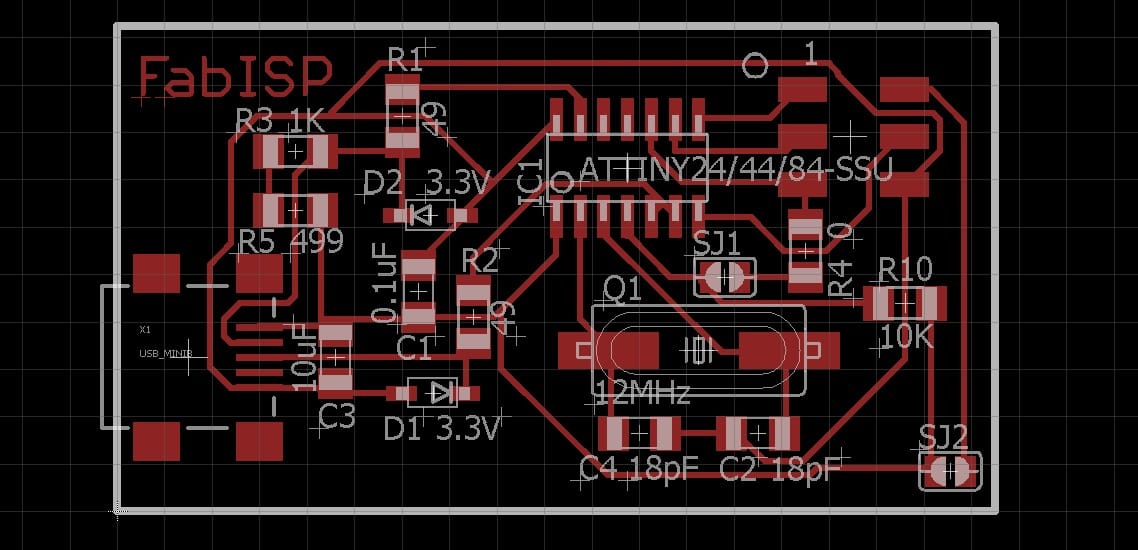
I have downloaded the fab ISP file from fab academy page The cirqoid machine we are using is supporting Gerber file for that I have downloaded the eagle board file from the following link FabISP.Then I opened the board file in eagle.
How to convert Gerber file:
Step 2:
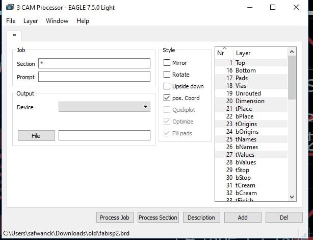
Click File → Open → Job → (for the cirqoid machine has one job file) that I have downloaded from this link Grabber File . Then I have selected the download file.
Step 3:
Click process job ( we can get the job file where we have saved the board file)
Working with Machines:
For the controlling cirqoid we are using cirqwizard software and the circuit milling I am using 0.20 bits for the cutting I am using 2.0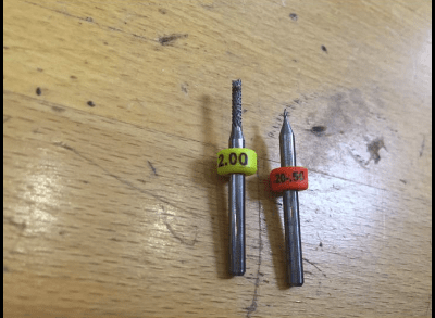
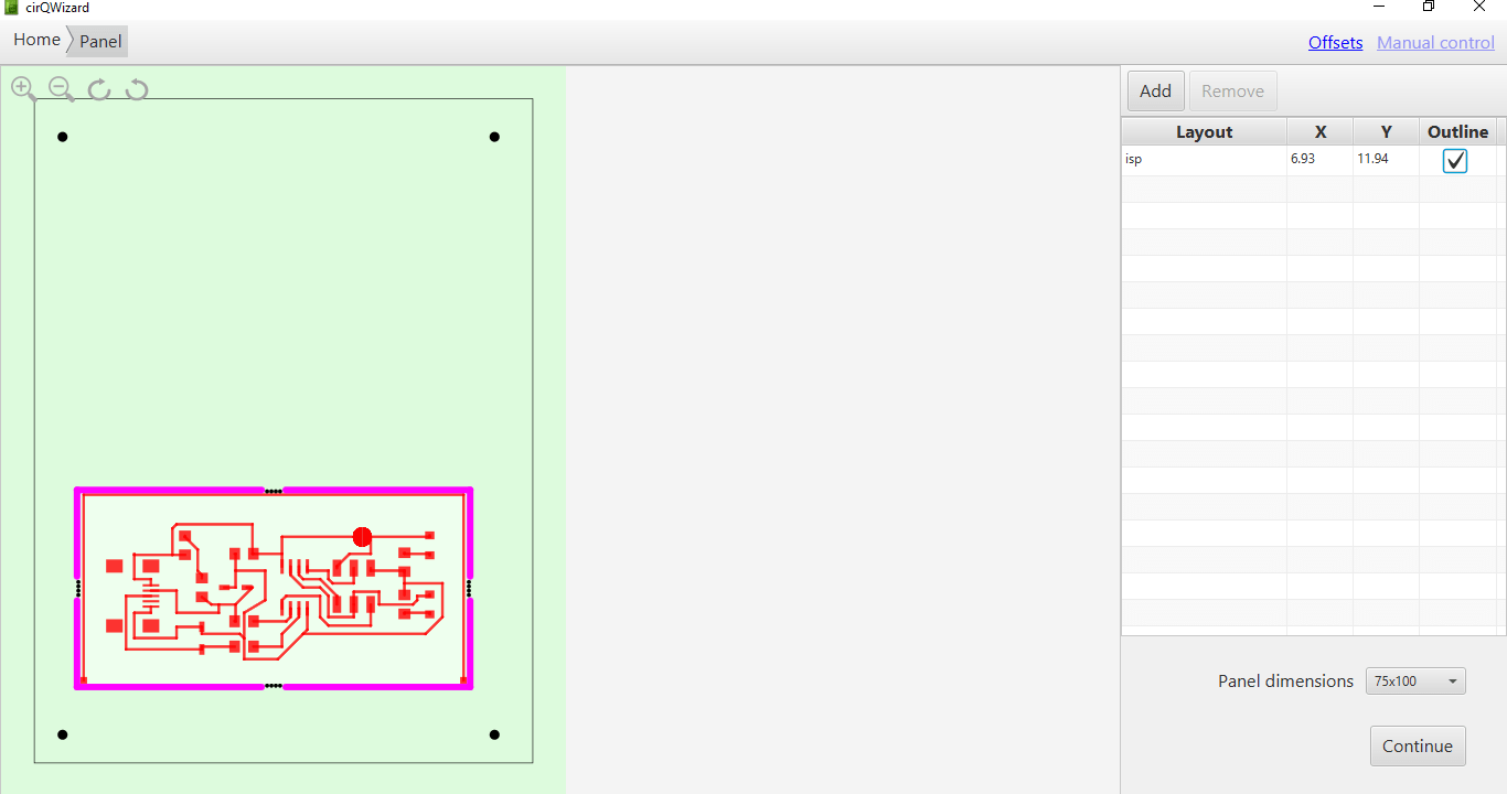
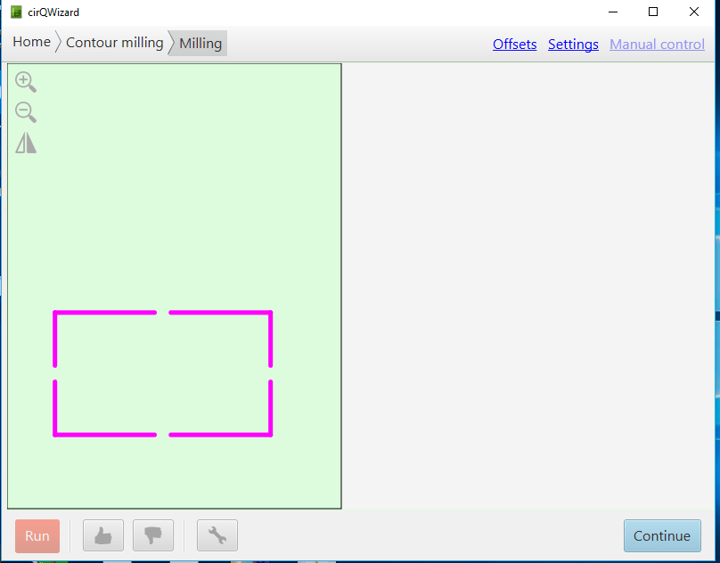
I have opened the design file in cirqwizard
Step 1:
Step 2:
Click → continue
Step 3:
Click home (we have to click home in order to find out that the machine is set correctly and moving towards the home position). After that click on the continue button.
Step 4:
It is written in the new window the following message: Put PCB on the machine bed for that we stick the PCB on the cirqoid machine, then click continue.
Step 5:
The upcoming window we need to establish Z offset. In that window there is an X and Y position to make sure that the measurements are put in the right place and give the Z value. Then we have to test the Z value is fine or not.
Note:
We gave is a Z value inorder for it to be the minimal value for depth or else it will make a hole and will break the bit
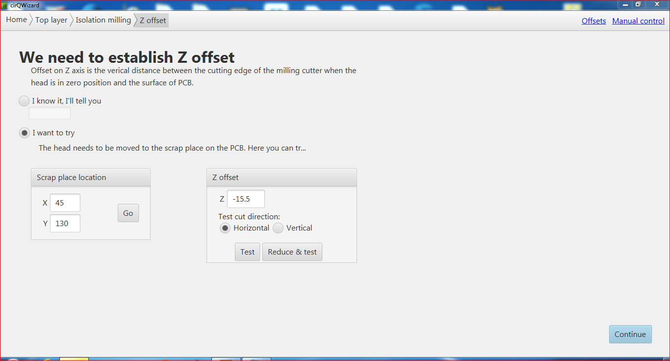
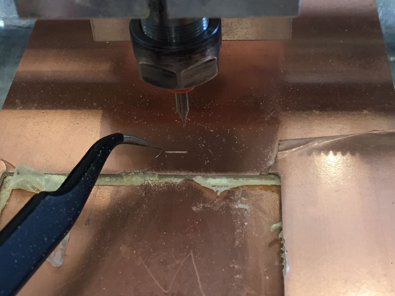
We can see how clear is the Z line that is why I gave the Z value -15.5 then I have pressed continue.
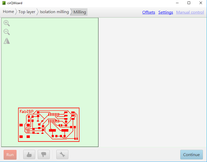
Step 6:
We can see the board in cirQwizard then I press Run and there where the milling will start.
Milling Result:
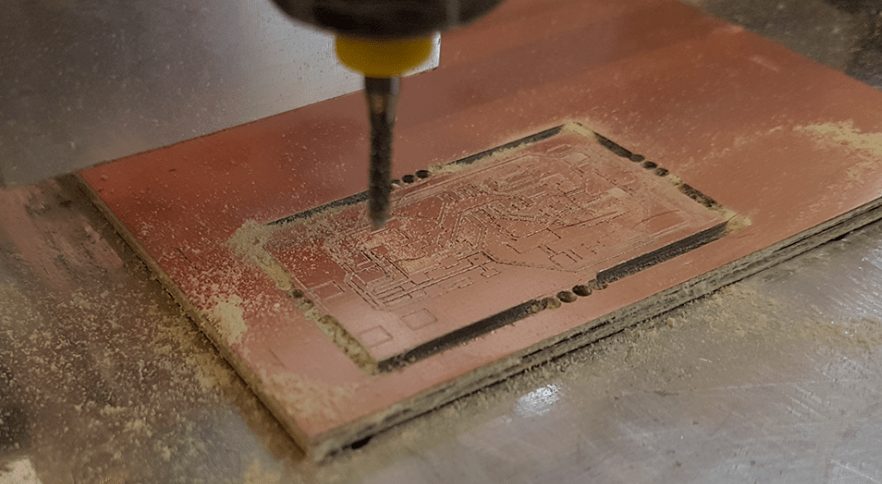
Step 7:
The milling process is over, the next step is that I have to cut the board for that I clicked continue. I had to change the bits for 2.0 for the new cutting board. Then the new window will open. In the new window process I have to drill a hole on all the four corners → press run.
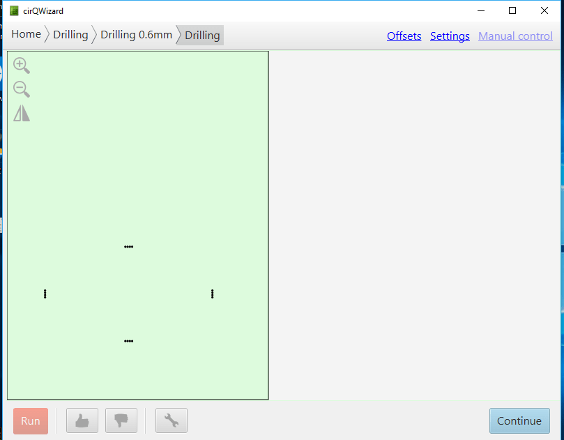
Step 8: The drilling hole is finished then I clicked continue, the upcoming window process is cutting for that click run.
Result:
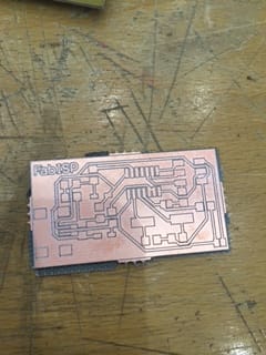
Stuffing the board:
My PCB is ready for the soldering, I had to make sure that I have all that health,safety, environment is covered. Because there are some toxic fumes
Components for soldering:
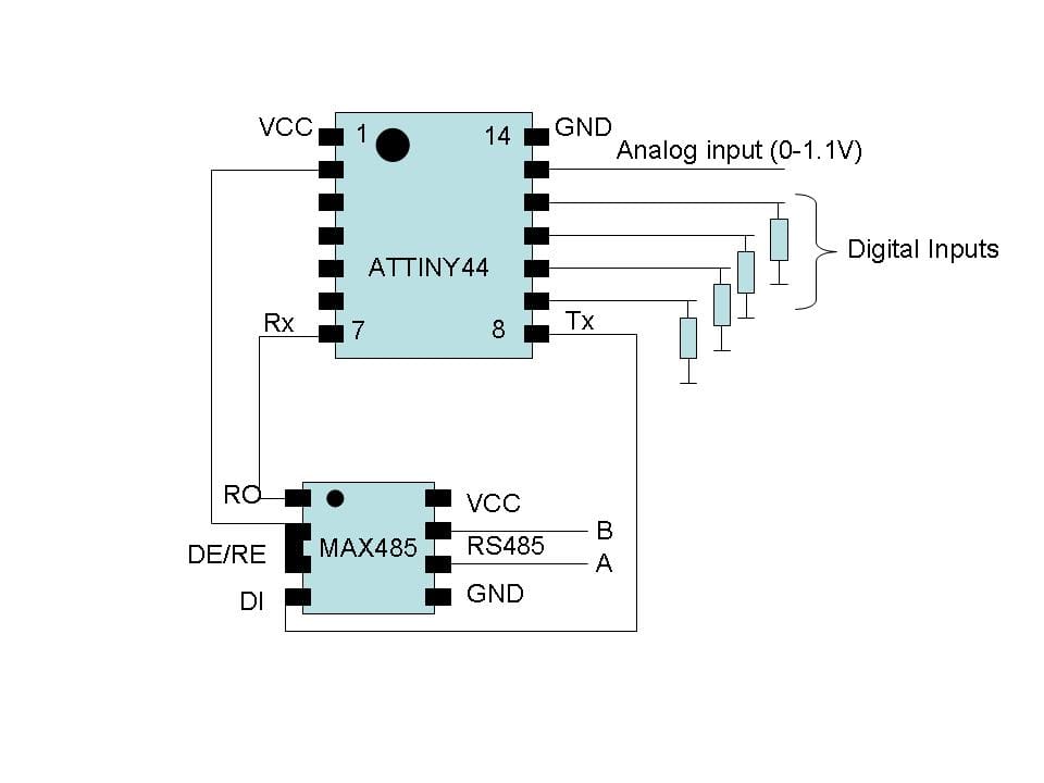
1- ATTiny 44 microcontroller
2- 1 Capacitor 1uF
3- 2 Capacitor 10 pF
4- 2 Resistor 100 ohm
5- 1 Resistor 499 ohm
6- 1 Resistor 1K ohm
7- 1 Resistor 10K
8- One 6 pin header 9- 1 USB connector
10- 2 Jumpers-0 ohm resistor
11- 1 crystal 20MHZ
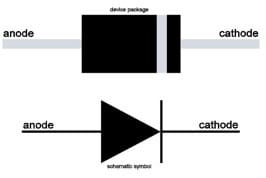
12- Two Zener Diode 3.3 V
13- One USB mini cable
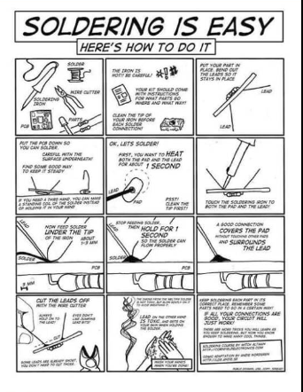
When you are soldering a micro controller make sure that you are soldering properly because there is a very little notch on the chip that is VCC that we have to assure it is in the correct position.
Diodes has a polarity thats why when you are soldering be careful of the polarities.
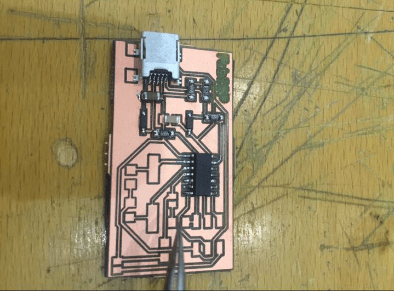
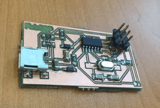
Result:
After the soldering I have checked the continuity. This is my first attempt for soldering and to be honest it turned out to be very easy not like I expected it to be. It is really interesting to understand how this tiny object could create a big difference in the world. Just little bit of concentration on amount of lead, be careful and precise.
Programming:
I am using Ubuntu for the programming I installed avrdude/GCC software and dependencies.
Open terminal then I typed:
1) sudo apt-get install flex byacc bison gcc libusb-dev avrdude
2) sudo apt-get install gcc-avr
3) sudo apt-get install avr-libc
4) sudo apt-get install libc6-dev
The installation process is finished then I have downloaded Firmware from Fabacademy page then I unzipped the folder after that I have copied the desktop
Then type
make clean
make hex
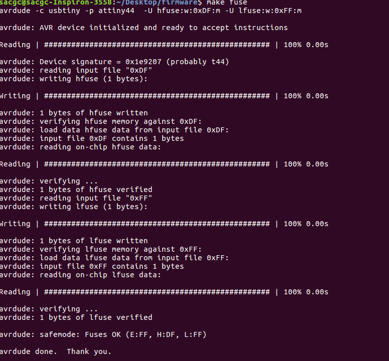
make fuse
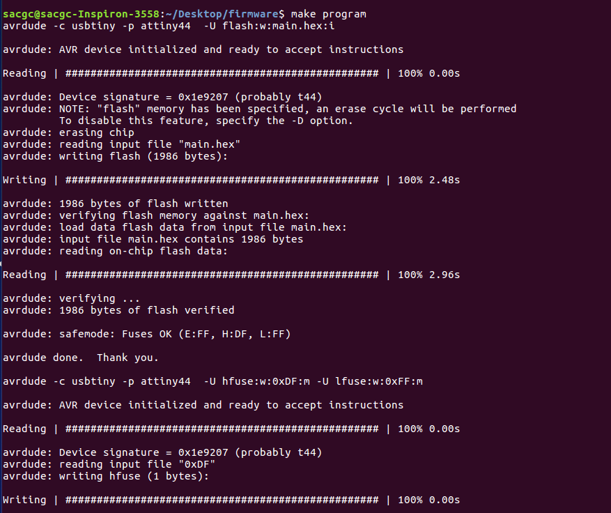
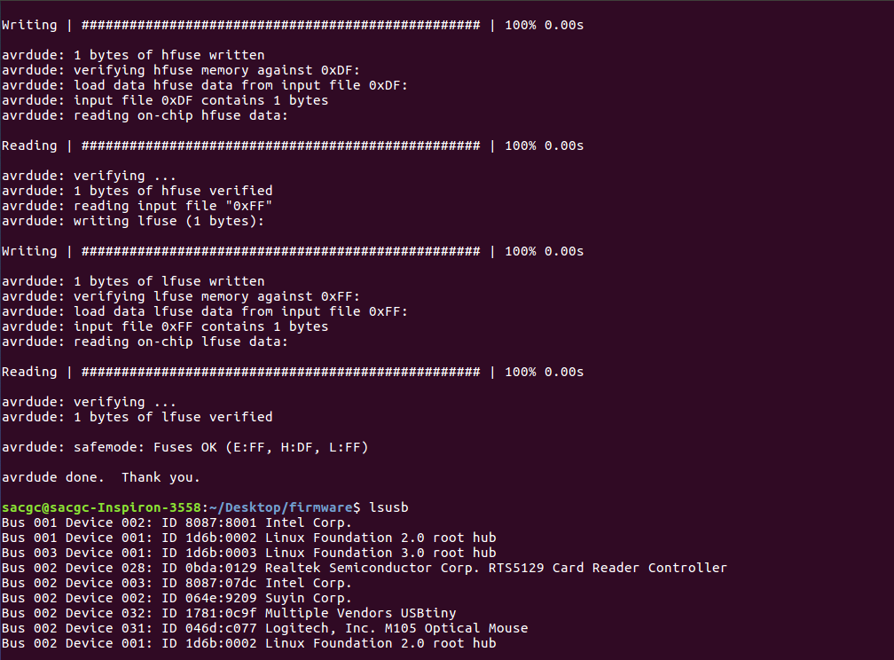
make program (the program is uploaded successfully)