Design and build a wired &/or wireless network connecting at least two processors.
About Networking & Communications :
Networking is simply connecting two microcontrollers together.
I decided to build a wired serial network using redesigned hello.bridge board and two hello.node boards .
Serial communication is the process of sending data one bit at a time, sequentially, over a communication channel or computer bus.
Most PCs have some sort of serial bus interface available. A serial interface is often easier to use for embedded systems.
Parallel communication is a method of conveying multiple binary digits (bits) simultaneously and protocols transfers multiple bits at a time using buses of data, it is easy to interface , but it requires more IO lines.
I2C is a broadcast topology network, like Ethernet. It's also a multi-master bus, which means that multiple chips can be connected to the same bus and each one can act as a master by initiating a data transfer.
What I did :
Design :
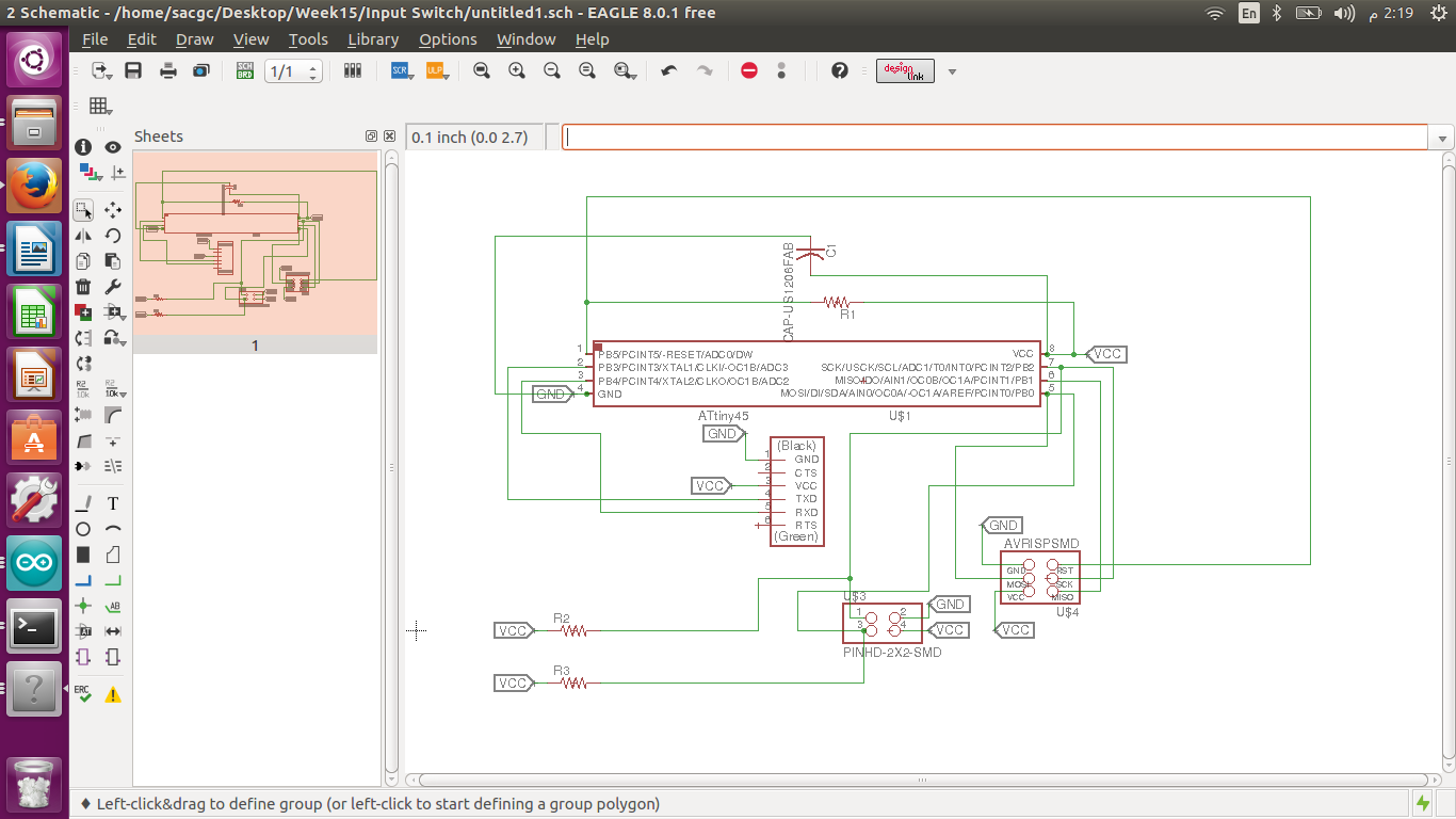
Main (Master) Board :
I designed my board and this is the Schematic view of my Master board , which I referred from Neil’s board.
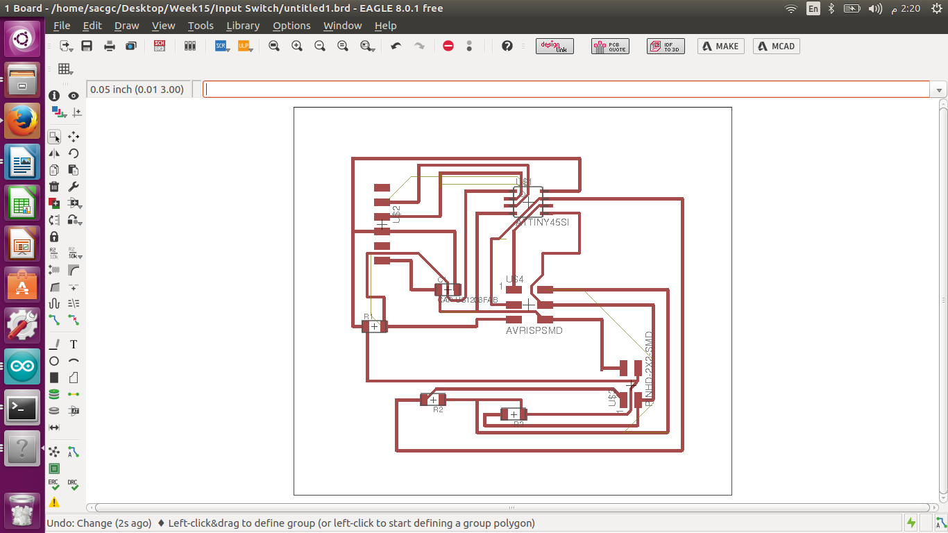
And this after I autorooted and manually rooted some of the roots to ease the soldering process and avvoid any shorts happening easily.
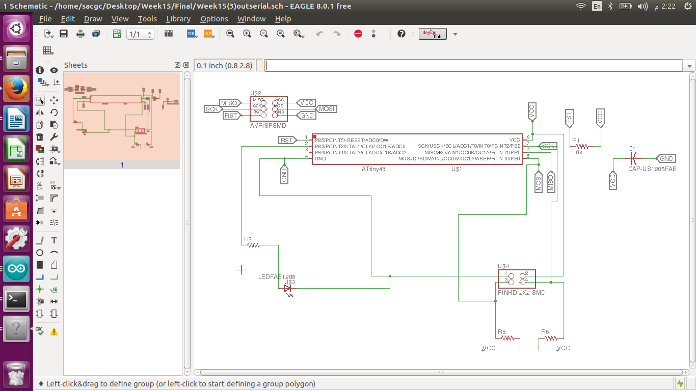
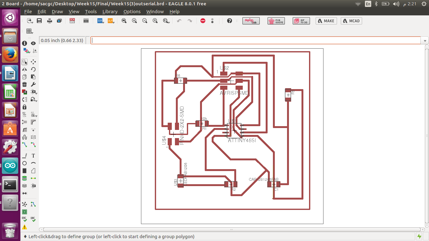
Slave Boards :
Above is the schematic and board for my Slave (Output) board which I decided to use LED.
I soldered one master board and two Slave Boards (LED two different colors Red & Blue) and burned the bootloader successfully for all three boards.
Milling & Soldering :
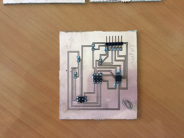
This is my main master board after I soldered it
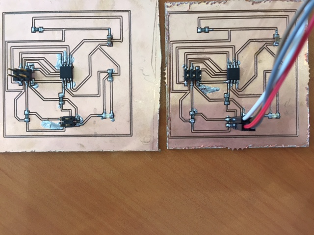
Above are my two slave boars which I choosed LED light for both of them (Blue & Red).
Programming :
Master Board Code :
I assigned the two slaves address in the master board code program. 0x1 for slave 1 and 0x2 for slave two
#include <TinyWireM.h>
void setup()
{
TinyWireM.begin(); // join i2c bus (address optional for master)
}
byte x = 0;
byte x1 = 0;
void loop() {
TinyWireM.beginTransmission(0x1);
TinyWireM.write(++x % 2);
TinyWireM.endTransmission();
delay(5000);
TinyWireM.beginTransmission(0x2);
TinyWireM.write(++x1 % 2);
TinyWireM.endTransmission();
delay(5000);
}
Slave1 Board Code :
I mentioned the slave 1 address (0x1) I defined in the master board code , so that slave 1 would join the i2c network.
#define output(directions, pin) (directions |= (1 << pin)) // set port direction for output
#define input(directions, pin) (directions &= (~(1 << pin))) // set port direction for input
#define set(port, pin) (port |= (1 << pin)) // set port pin