...
-
About Me
Yousef Almutairi, 29 years old, I am an elder brother. Which means I am used to takeover on most of our family responsibilities since being an adult and dig my way to build a great future after graduating from high school, mostly by myself.
I experienced a lot of life adventures, addicted to explore new thing and traveling around the world from far east to far west. The most important lesson I learned from all of these adventures that everything have a positive side in it, even wars or sickness, but you have to focus on that positivity to pass this time as a winner and believe that this time will pass if it is good or bad which means planning to my next step is a must.
I have been taken by technology since I was a child. My golden chance was when I attended my first day training course in Kuwait FABLAB. What has really attracted me are the gadgets I saw there. I found an opportunity in FABLAB to explore, discover and learn about new subjects that can help me improve my technical and mechanical skills.
,
-
Build a personal site describing you and your final project.
-
Plan and sketch a potential semester project and add it to your website.
-
Upload it to the class archive. Work through a git tutorial.
- Model (draw, render, animate, simulate, ...) a possible final project, and post it on your class page with original 2D and 3D files.
-
make lasercutter test part(s), varying slot dimensions using parametric functions, testing your laser kerf & cutting settings (group project)
-
cut something on the vinylcutter
-
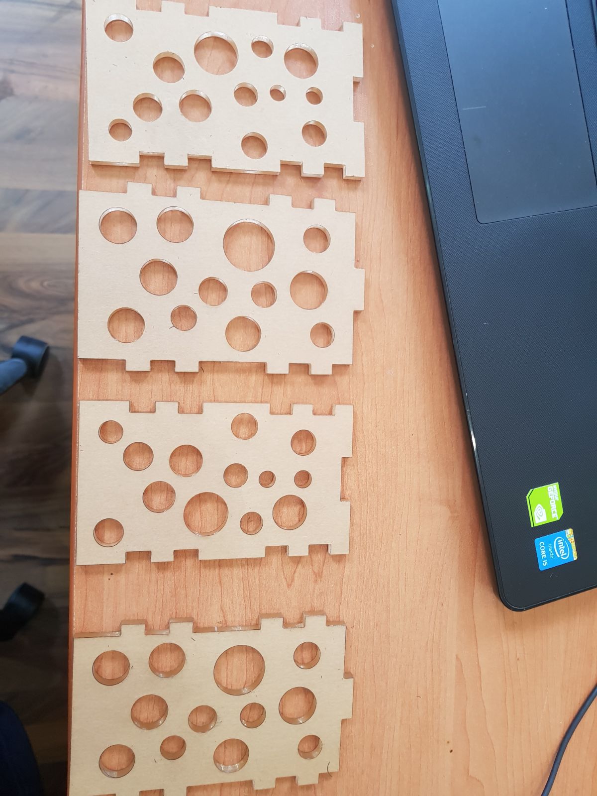
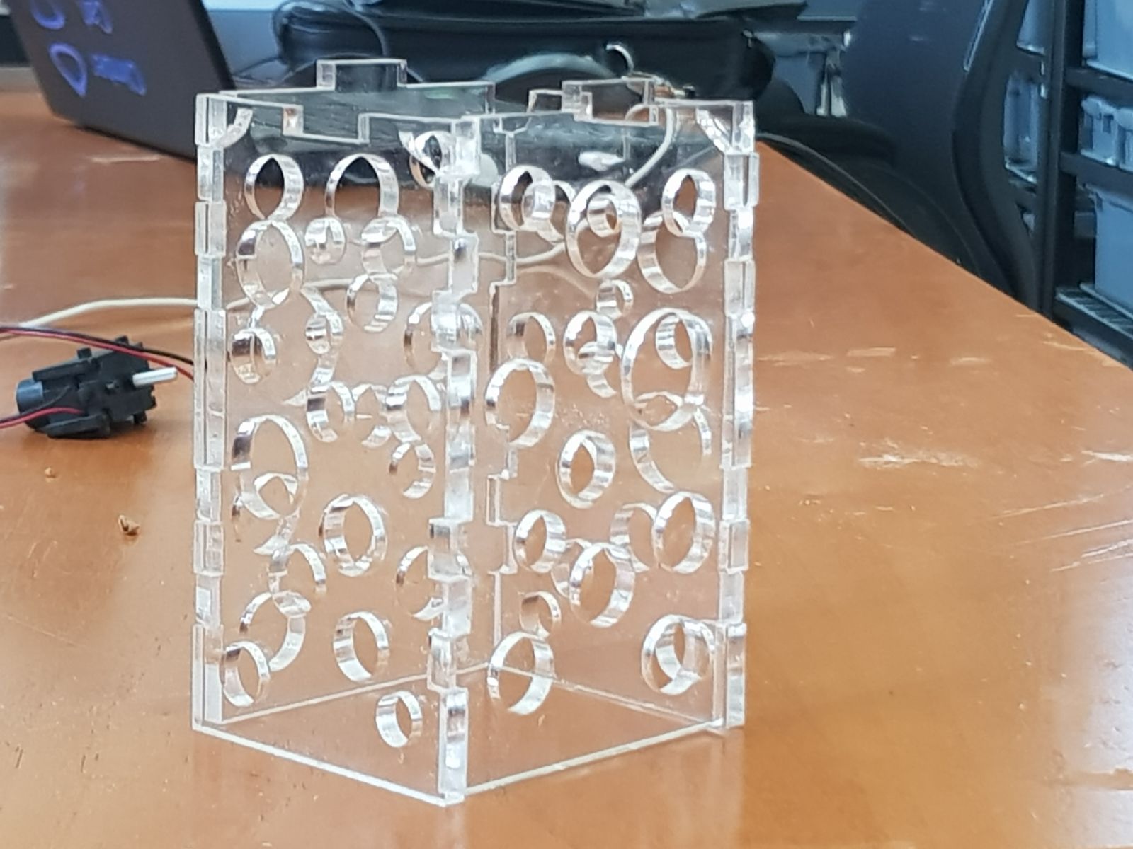
design, make, and document a parametric press-fit construction kit, accounting for the lasercutter kerf, which can be assembled in multiple ways
-
Make an in-circuit programmer by milling the PCB (program it, so that you can use it to program your board in Electronics Design week, and in other weeks)
-
Optionally, trying other processes.
- Test the design rules for your printer(s) (group project)
- Design and 3D print an object (small, few cm) that could not be made subtractively
- 3D scan an object (and optionally print it)
- Redraw the echo hello-world board, add (at least) a button and LED (with current-limiting resistor), check the design rules, make it (if you have time this week, test it).
- optional: simulate its operation. Measure its operation
- Make something big (on a CNC machine).
- Read a microcontroller data sheet.
- Program your board to do something, with as many different programming languages and programming environments as possible.
- Optionally, experiment with other architectures
My Progress
...

Week 1
personal site

Week 2
computer-aided design
Week 3
computer-controlled cutting
Week 4
Electronic Production
Week 5
3D Scanning and Printing

Week 6
Electronics Design
Week 7
Computer-controlled machining

Week 8
Embedded Programming

Week 9
Mechanical Design
Week 10
Output Devices
Week 11
Machine design
Week 12
Moulding and Casting
Week 13
Input Devices
Week 14
Composites

Week 15
Networking and Communications

Week 16
Interface and Application Programming

Week 17
Applications and Implications

Week 18
Invention, Intellectual Property, and Income

Week 19
Project Development
Contact Me
...
First week
Principles and Practices, Project Management
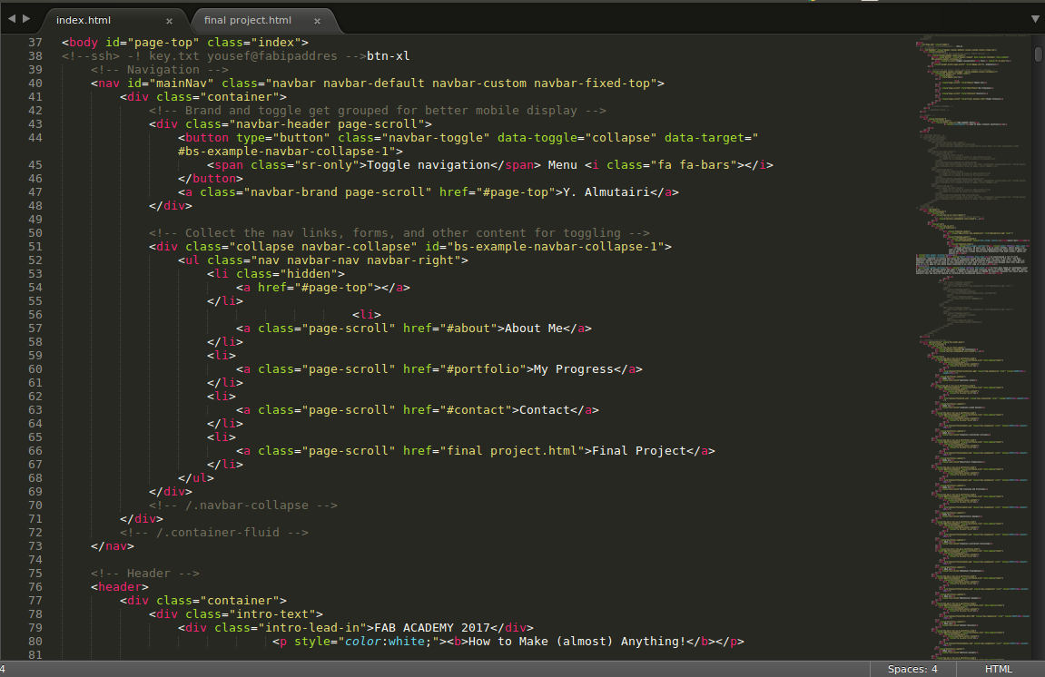
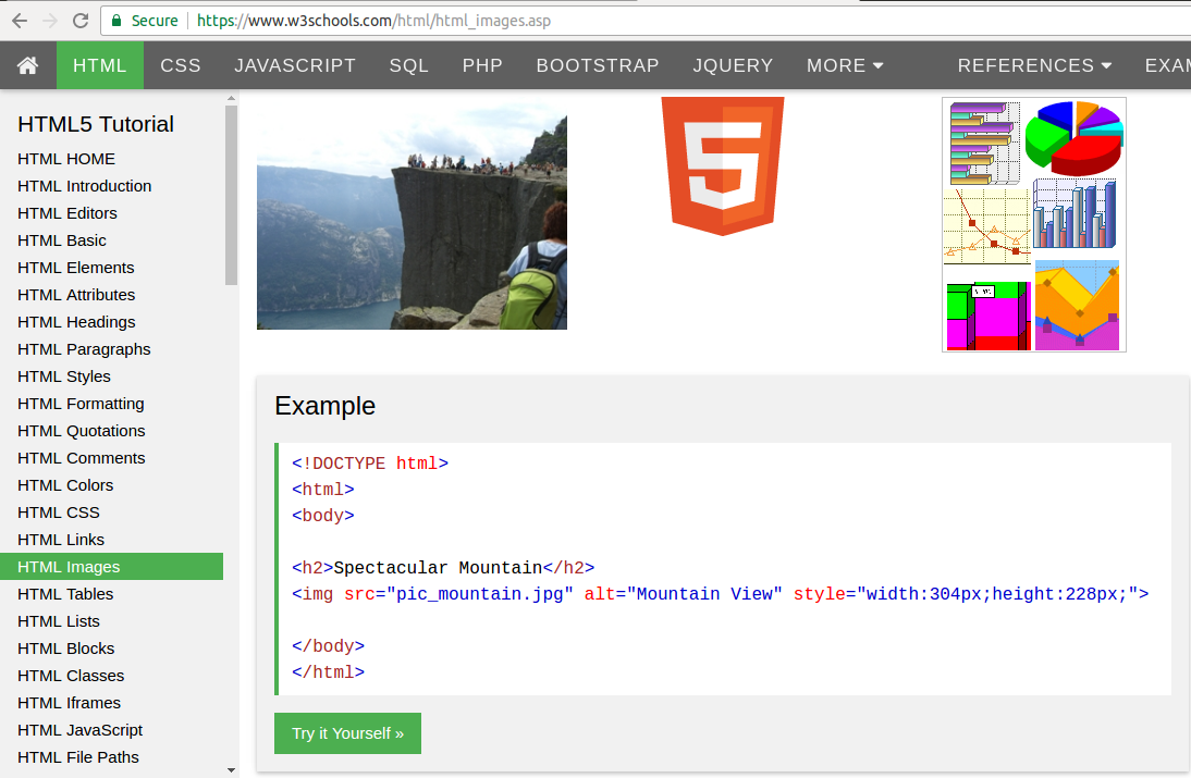
During the first week, we learned about the tools and the programming language of creating web pages. They can help me create my personal web pages. First, I got a template from Free-CSS. Second, we used the Sublime Text Program to create and edit our personal pages. I used sublime to add and edit text images and hyperlinks through HTML codes, which I took from W3schools. Third, I changed some of the text color by using the CSS to make my own design. Google Chrome was very helpful to find the right line by using "inspect" feature. Furthermore, I learned about the SSH Protocol which helped me in connecting and securing the information transferred between the client and the server. Then, I applied it in my website to connect it with FABLAB secure server. One of the control systems that may help me is called Git. It tracks changes in computer files. It also coordinates multiple files. It is mainly used for software development.
Web Development Tools
Google Chrome (Inspect): Google’s one of the most powerful elements in the space of web development is Inspect Element. To see the internal structure and coding of a web application or website, you have to only right-click anywhere in the page of the web and select “Inspect” from the context menu. The Inspect Element tool provides the details of a web page such as HTML, styling of the page, source codes, images and graphics, JavaScript and form requests. In addition, one can view the loading time for a web page through the Inspect tool. Other aspects of the site that Inspect helps to identify include download time, bandwidth and website typography.
Inspect can also allow one to modify some features on the webpage. Briefly, Inspect element tool is essentially for helping developers to identify the problems in a webpage, identify things that are fixed right and check the features of the website.
Sublime Text
Sublime Test is a rich-feature text editor that most developers have preferred in writing their codes on. The tool allows one to enter the pieces of code, save the codes, edit the codes, print and even create folders and files from within. The text editor is neatly arranged with a blank file having a fixed length of lines, blank numbered lines and a menu to customize the codes. Sublime text has a pre-defined keywords for web development that allows the developer to enter certain codes with ease by autocompleting them. The text editor also has special commands to manipulate the codes. Special commands include command for creating a new page, saving codes, printing, changing the editor settings and scrolling.
HTML
HTML is an acronym for Hyper Text Markup Language. HTML is a web programming language that allows one to develop webpages. In HTML, you develop a website locally before hosting it on the web server where all internet users can view it through a domain name. HTML is an easy to learn and use language while it provides powerful and basic features that all websites use.
HTML coding is a process of using short lines of codes called tags. Most of the tags have opening and closing tags while others have opening tags only. A developer uses these tags systematically to develop a webpage before saving it with a special extension “.htm” or “.html” for the browser to recognize the output format. Nearly all browsers have a capability of reading “.htm” and “.html” files by reading and translating the tags and values into visible output. HTML codes are written on a text editor such as Sublime Text.
For All kind of HTML codes like, HTML Graphics and HTML Media, you can visit W3schools
CSS
CSS is an acronym for Cascading Style Sheets. CSS is used majorly for styling a HTML document or webpage. CSS styles the webpage by allowing a developer to apply some effects to the webpage. Some of the aspects that CSS can style include font size and family, background color, font-weight, layout of a page and positioning of elements. CSS also allows a page to be viewed easily over various screen sizes. CSS can be applied in three major ways: inline CSS, internal CSS and external CSS.
SSH
Secure Socket Shell or SSH is a common term in web development. It involves provision of a secure set of utilities and protocols for access a remote sever or computer. Most modern websites allow users to enter their data into the website to access certain features of the site. To link and utenticate the users through the remote web server, there is need to encrypt the information or data provided by the user. SSH is used to encrypt the data from the browser to the remote computer or server. This helps to avoid loss of information or access of the information by unauthorized people over the Internet. SSH is commonly used in websites that have authentication, online payment and others that handle personal information.
Git
Git is a collaborative tool that was developed in 2005 by Linus Torvalds to be used as a version control system or VCS. As a VCS, Git helps web developers to track changes in programming files while allowing different people to make changes to shared files. The tool is not only used in web development but also software development in general. The aim of Git is to allow collaboration on web development project, improve integrity, speed and support distributed workflows.
Implementation of GIT and SSH:
( To open a terminal click on Ctrl+Alt+T together )
1- Create account in GitLab "http://git.fabacademy.org"
2- Installing Git on the laptop, update the version and packages by typing this code in the terminal
“ sudo apt update “
and then install Git by
“ sudo apt install git “
3- Generate SSH keys commands.
"ssh-keygen -t rsa -b 4096 -C “my email: youseef.q8@hotmail.com”
password well be required so I set a password and confirmed it.
4- Checking the availability of the SSH Agent
"eval "$(ssh-agent -s)""
5- Add the key to the SSH agent
"ssh-add ~/.ssh/ id_rsa"
6- Connecting laptop with GitLab use your username and email account
"git config --global user.name "yalmutairi""
"git config --global user.email "youseef.q8@hotmail.com"”
7- Adding generated SSH public key to GitLab account first get the Key data sudo gedit ~/.ssh/ id_rsa.pub" and copy the content data
8- Then go to Gitlab Account and click on Profile Settings → SSH Keys, paste he content data in the key section and add a key.
9- Cloning the repository from fablabkuwait to the local laptop "git clone git@git.fabacademy.org:fabacademy2017/fablabkuwait.git".
Website Templates
A website template is a set of HTML files with pre-defined codes that allow manipulation and modification when creating a website. Web templates contain a an easy to follow codes that have sections for plugging in new content such as images and word texts. Most web templates are designed to avoid complex coding processes. Therefore, individuals with little or even no coding skills can use web templates to build websites.
Uploading to Archive
The following codes is to upload our files to archive ( images, videos, codes etc... )
git pull
git add --all
git commit -m "comment"
git push
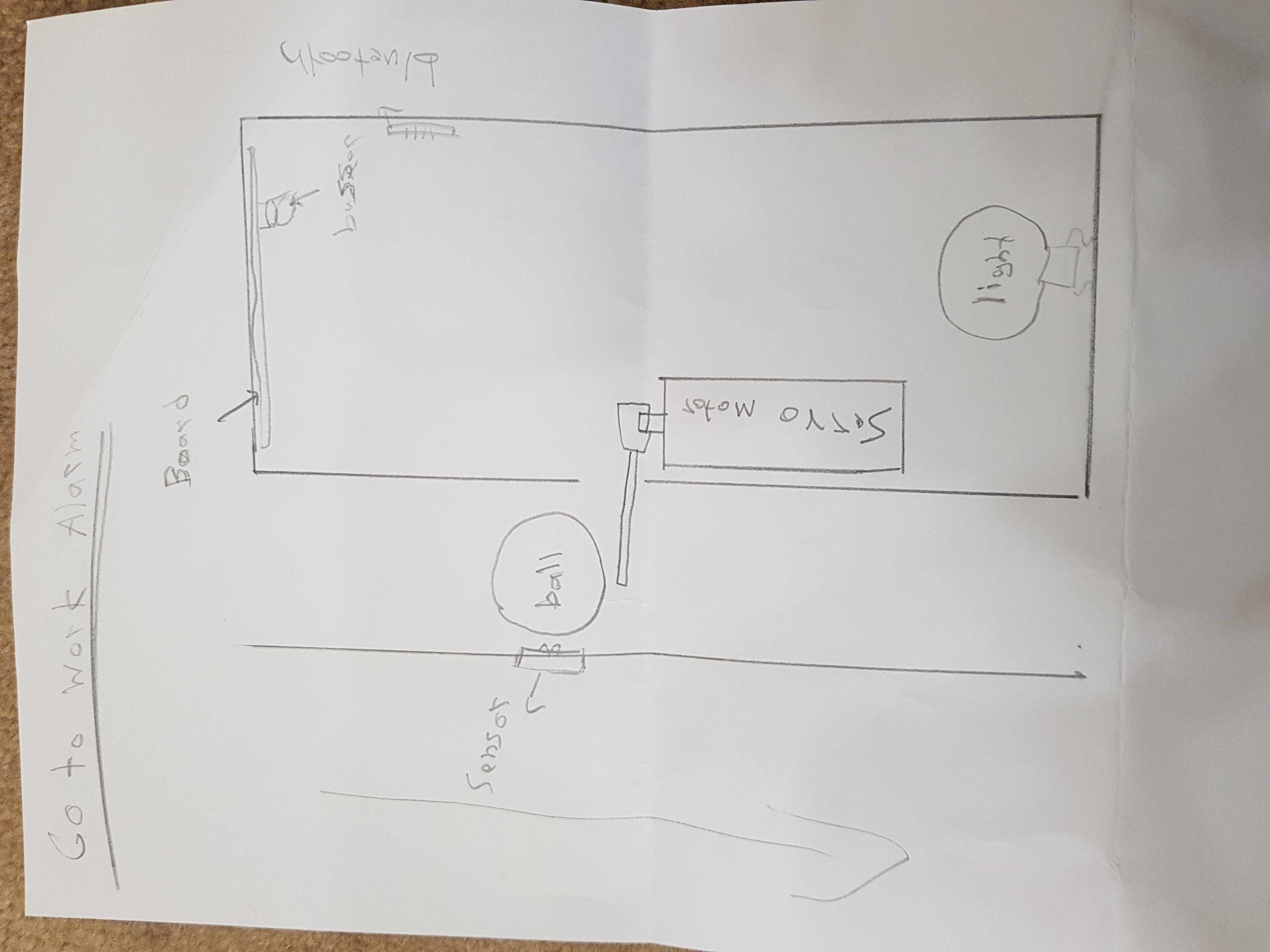
My Final Project Sketch
Introduction
This alarm project is done to make you wakeup and move from your bed to switch it off. A ball going to fall dawn from the alarm when it start peeping, and to switch it off you need to find the ball in put it back inside its bath in the alarm box. And for decoration purposes the alarm been made as it a floor light and added I light inside the alarm box.
Second Week
Computer-Aided Design
About CAD
CAD is an acronym for Computer Aided Design. CAD software is an application that is used by engineers, architectures and drafters to create high-precision designs of objects and other technical illustrations. CAD software has the potential to create a multi-dimensional illustration or design.
Vector VS Raster
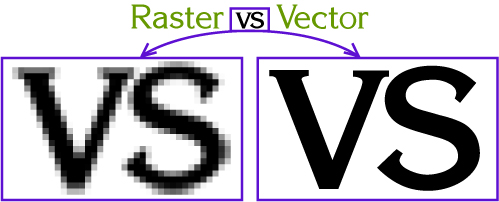
Comparison between Vector and Raster Images
A vector image is a collection of paths of mathematical functions that make up a picture. Mathematical functions in a vector image define the image properties and borders. Due to these mathematical function, vector images are not affected by the pixels when it comes to resolution. Raster images on the other hand are highly affected by the pixels, which decreases their resolution. This is because raster images are made up of tiny elements called pixels. Pixels are used to determine the properties of an image. Most normal pictures like photos are displayed as raster images while vector images are used to display simple images and illustrations.
Vector images have their mathematical images scaling easily when the image is scaled hence not affecting the resolution. Raster images on the other hand may lose their quality in terms of resolution when the image is scaled because the pixels becomes widely spaced leaving fuzzy lines.
An erasing tool can remove some pixels from a raster image easily. Vector images on the other hand does not allow erasing of the mathematical functions that make up the image but one can only set certain constraints to trim the paths making up the image.
2D Design
GIMP
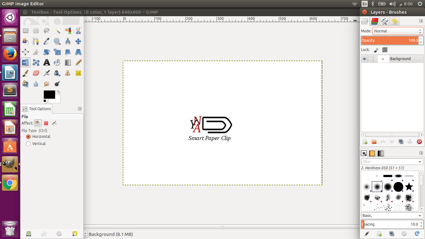
GIMP is a lightweight graphics editor software that is used mainly for retouching raster images. GIMP has an open source license thus it is free to acquire and install. GIMPS supports additional features for editing and layering a raster image and organizing the designs to produce magnificent artworks. Just like in in Photoshop, GIMP is also rich in multiple features.
Before I start to using GIMP to design my logo, I took a quick look to Youtube videos to know how to use the tools of this program. It was not difficult I got what I need, then decided to use the gimp software in my final project logo . Then I start by designing each letter in my logo like changing size, color and the angle of the letter and combining the layers to gather. after that I import a picture from Internet resize it to fit it with the logo.
GIMP is user friendly, I did not face any difficulties using it even though it was my first time.

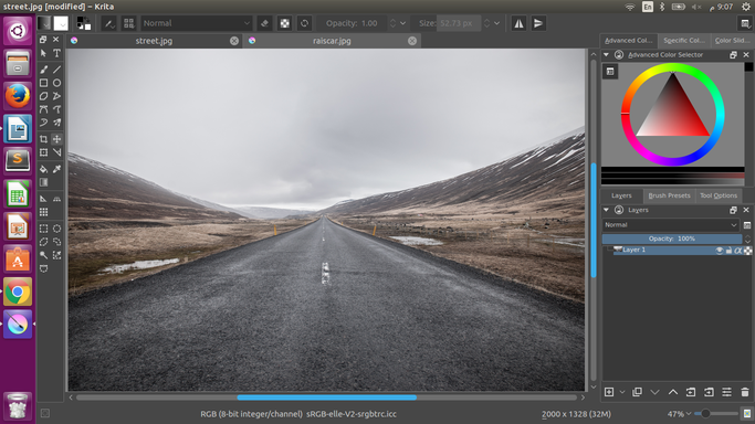
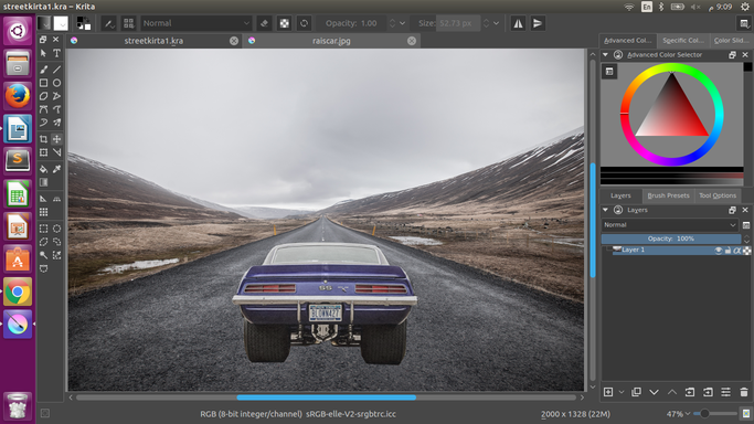
Krita
Krita is also a graphics editor software that is mainly for raster images. Krista provides several features that allows one to customize an image and get the desired artwork. The software supports several commands and other keyboard shortcuts that are useful in image editing.
For me as I did not ever try to use any of these programs because simply I thought it is going to be hard. After all this years of ignoring any kind of this programs am learning from the first time and am finishing my work. All what it needs in to understand the tools and how to use it. I always relay on youtube videos.
First I Google how to download and install Krita . Then I watched Introduction to Krita on Youtube. After that the fun is started, where I dowloaded street and sport car picture. I start Krita program and open them I use bezier curve selection tool to select and cut the car pic the copy it to be on the street layer. Then I use move and transform tools on order to fit the car picture in the right place. After that I decrease the opacity of the car picture to make it transparent.
3D Design
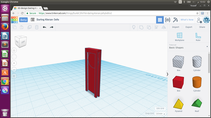
Tinkercad
Tinkercad is a simple and easy online 3D design tool, which help anyone in creating 3D toys, prototypes and minecraft, you can almost create what ever you want.
I used it to create first draft prototype for my final project. (Smart Paper Clip). Where I use the square shape and shaped it to rectangle then a made some holes to create space for the bluetooth device and the bar code which am going to apply on the paper clip. I use the grouping tool to connect the parts of it to gather.
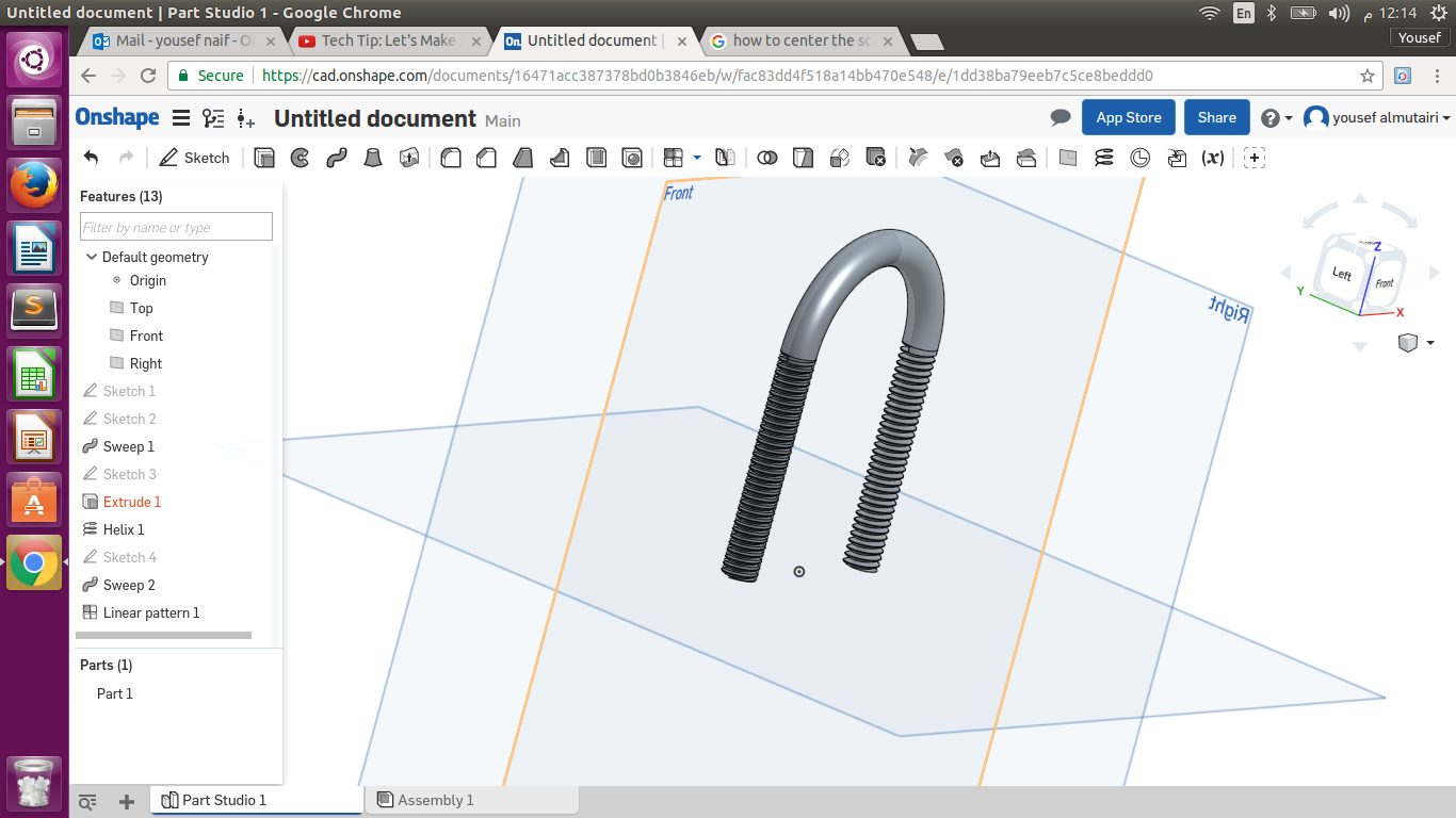
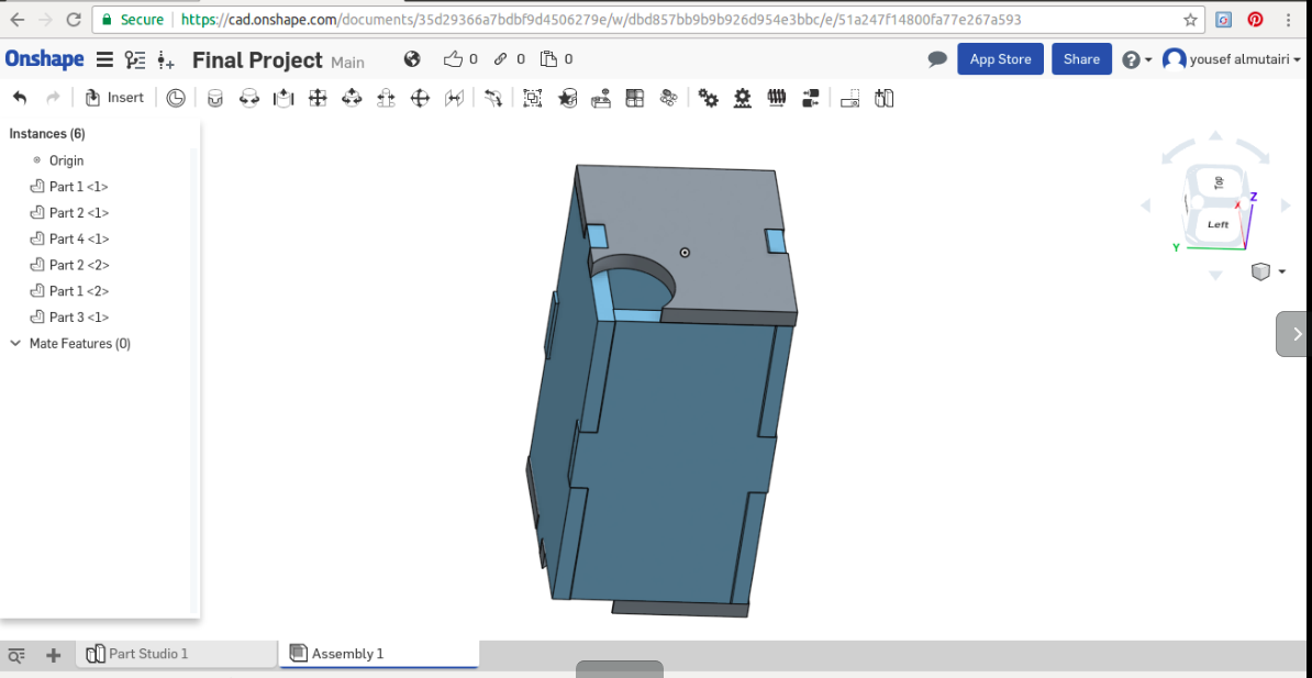
Onshape
Here to comes, Onshape was the hardest 3D software and at the same time it is the best that I used. Finally I discover how are the engineers design the models they need.
First, I went to Onshape site and sign up for professional trail to start exploring the software. I decided to model U Bolt as there is videos to help in explaining the onshape tools and showing how to create U bolt.
I start new sketch I draw to lines and an arc for the curve above. Then I use the sweep tool in creating a path. After that I use the helix and I draw triangle then attached them to gather using Pierce tool to help me creating the sweep which going to shape my U bolt. Last I create new part with the sweep so I can apply it to the over part if the U bolt. Finally I save it to my account.
 Onshape File
My Final Project 3D Design
Third Week
<Computer-Controlled Cutting
Laser Cutting
Comparison between laser cutting and mechanical cutting
The traditional mechanical cutters are very different from the laser cutter in the features and methods of cutting. While mechanical cutting involves physical contact between the cutting edge and the material, laser cutting do not have a point of contact between the machine and the material. Laser cutter users a narrow blow of gas to melt out the unwanted material. Laser cutter provides a very minimal change for contamination while mechanical cutting has a very high chance of contaminating the material to be cut. There is no wear of the material in laser cutting while mechanical cutting is dominated with wear of the material. Mechanical cutting has a lower cutting precision as compared to laser cutting. Laser cutting involves consumption of very high among of energy hence hard to implement in metal fabrication systems. Mechanical cutting consumes less energy hence effective in metal fabrications.
VINYL CUTTER
A vinyl cutter is a type of computer-controlled machine. Small vinyl cutters look like computer printers. The computer controls the movement of a sharp blade. This blade is used to cut out shapes and letters from sheets of thin self-adhesive plastic. Vinyl-cutters used to make 2D Stickers. To make sure there is clear contrast between colors in the the boundary sticker should be in ( Black & white ) only so the cutting goes well. The picture to import is PNG format.
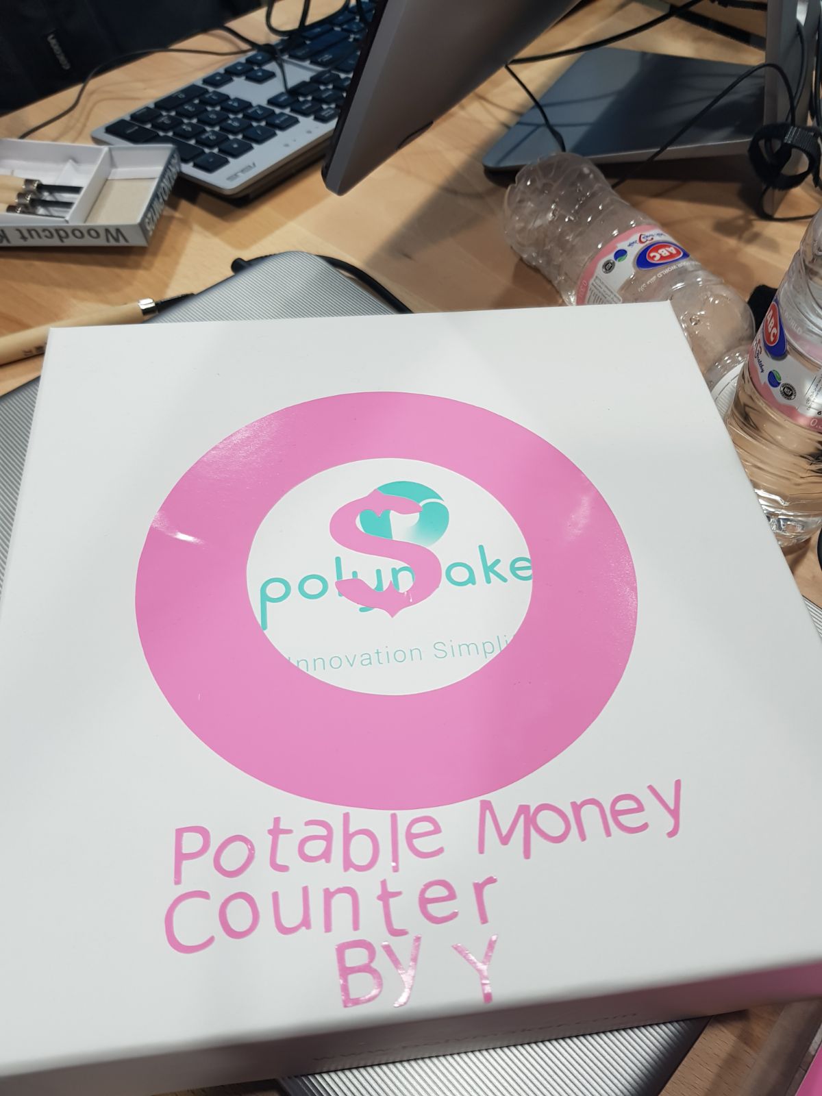
This week I use Ink-scape to make the sticker and cutting it with knife cutter, I decided to do the logo for my final project and it was very simple. Using the grids to making sure the sticker is in the size that I need. I import I PNG picture from Internet to start with. After a finish my logo I faced problem with knife cutter, the letters was removed because is was small so I go back to adjust the size and do the cutting again the second attempted was successful.
Printing the design, I used Silhouette Studio program, steps in the following.
- Open the file, adjust the dimension and the printout location on the worksheet. Then click on object then trace and select the area. And keep the traces area. Finally send the job to the printer and print it out.

Filed Attempted
The Letters under the logo did not get out clearly, the problem is the design was lettel small. So I resized it again and I success in the second attempted.
Sticker File
Laser-cutter
Laser cutting involves a machine called a laser cutter to develop a surface cut. A laser cutter is a machine that uses laser beams to melt, vaporize or burn some surfaces of a material while leaving other surface as a highly shaped surface. The laser cutter shapes material surfaces by removing debris and unwanted parts thus leaving a fine surface material.
Benefits of Laser Cutting
Laser cutting provides a precise and quiet cutting process. The process is quiet because there is no contact between the cutting machine and the material. It is also very precise because it uses a thin stream of gas or laser beams. Laser machines are enclosed completely in a material to avoid damages to other materials and prevents accidents.
Laser cutting is very fast due to high equipment speeds and faster feed rates as compared to other cutting methods. Laser cutting also allow development of prototypes through a touch screen computer hence increasing precision.
I also used ink-scape to make the shape for the final project ( Portable Money Counter ) and cutting it using laser-cutter machine. First I use the grids spacing 1MM for X & Y. I use the draw Bezier curves and straight lines tool to draw the first prototype of my final project. After I fished form the shape I saved it as DXF file and I went to the vinyl-cutter and imported it using silhouette software to start the cutting. But after I got the shape out the part of it was movable. So I resized the part again also the second attempted was successful.
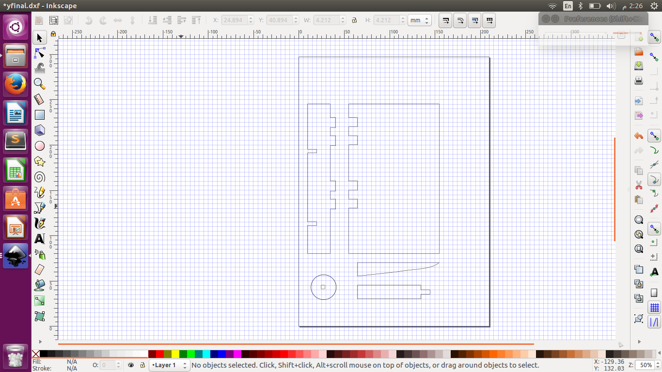 Final Project File
my failed attempt.
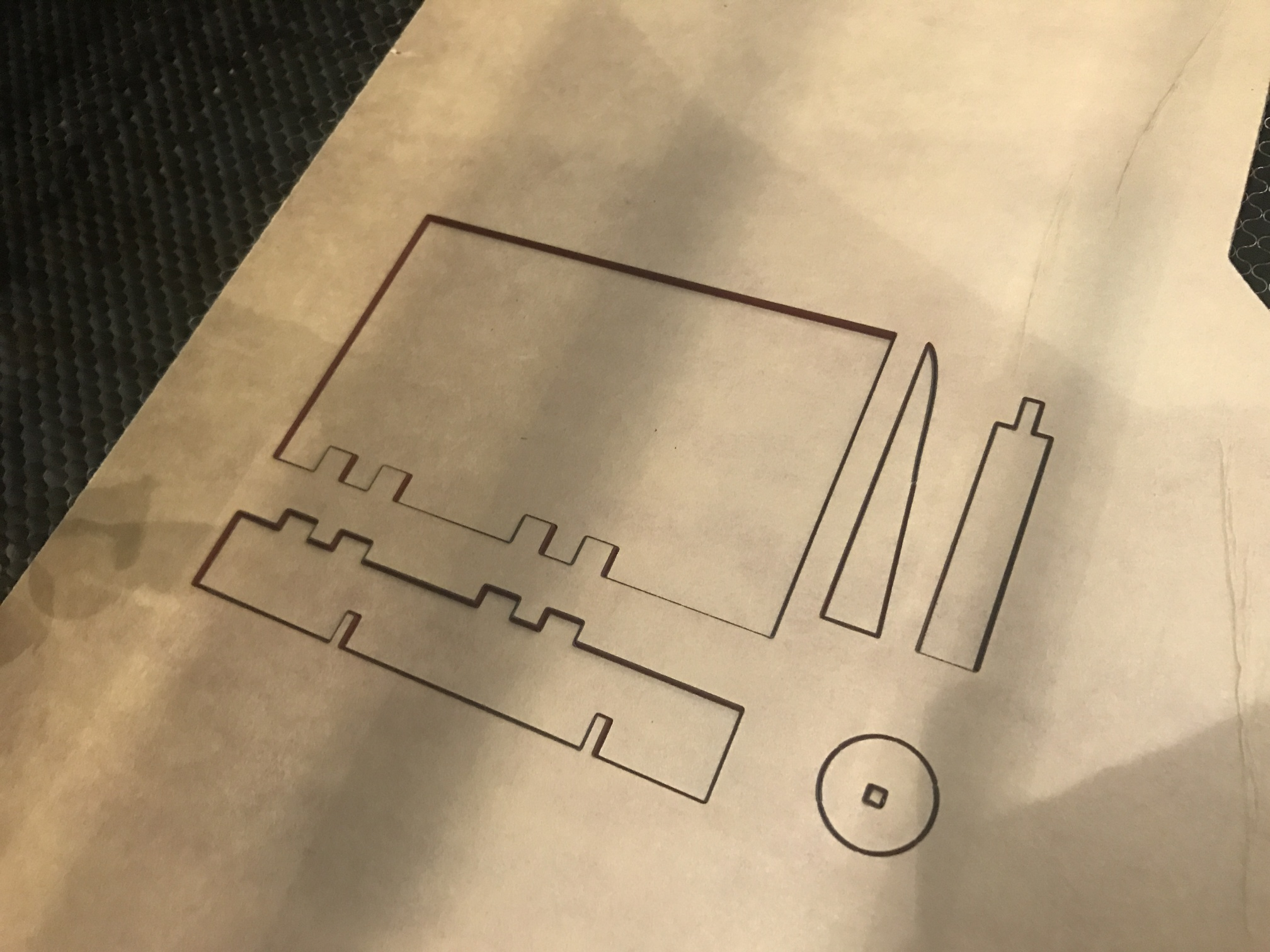
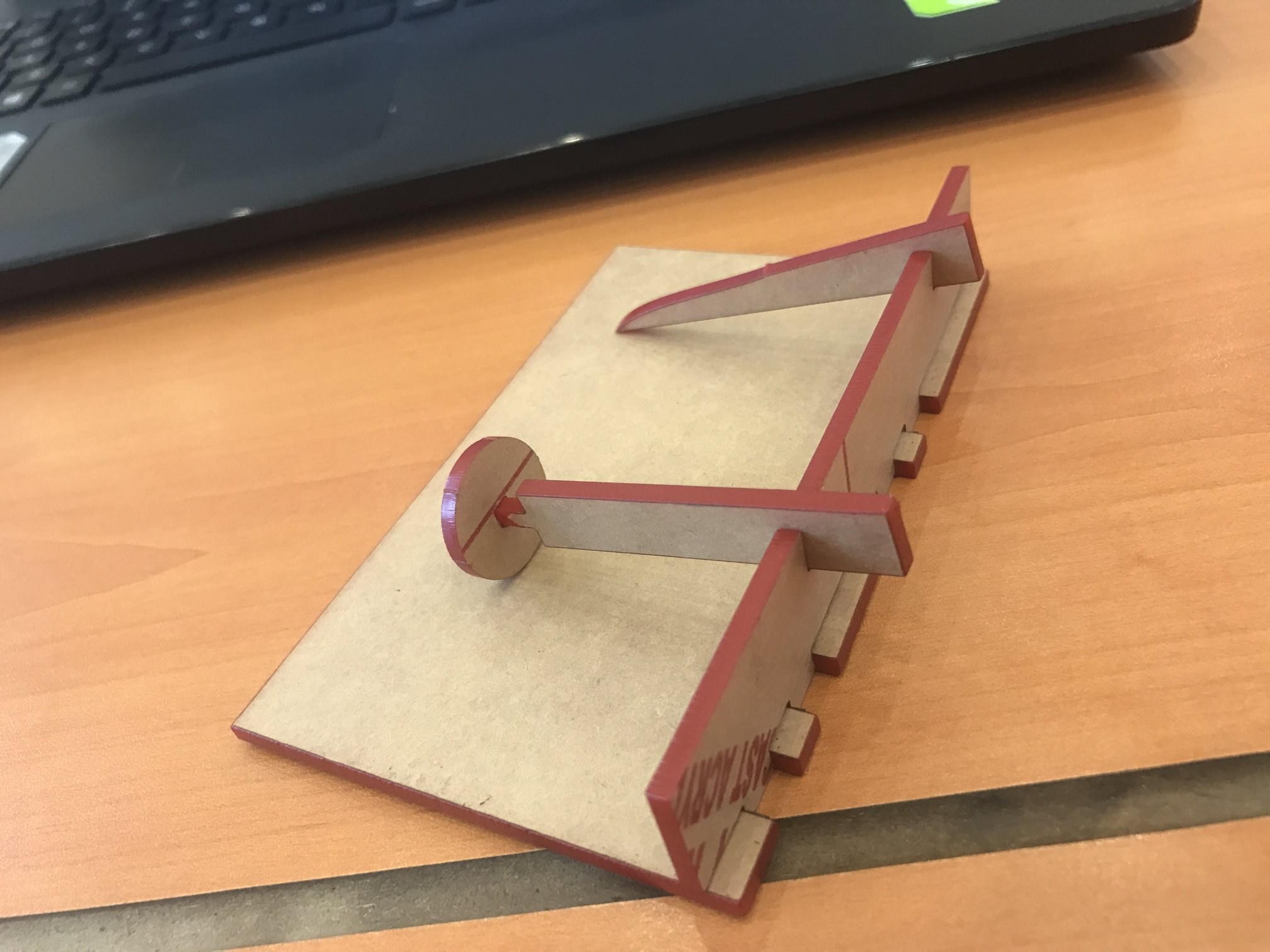
I realized that I should not use ink-scape to make the shape I need because it is not helpful to make the cutting part right as I had to re-do my work again to not have the parts of the shape loosing apart. but this time i did something else
This time I try the on shape program and it was very good from the first attempted..
Fourth Week
Electronic Production.
PCB Mailing
This week’s learning was about making our own PCB or Printed Circuit Board that will help us design various electronics. A Printed circuit Board is a board that is neatly designed using a copper clad sheet that will help us design electric systems by fixing various electronic components on it. The copper sheet or copper-coated sheet is placed on a non-conducting material to help prevent the flow of current to external components. However, during the design of our electronic systems, we will create pathways on the board by removing the copper sheet. We also learnt from this week’s lesson that there are different ways that one can make a PCB. These methods include milling and etching. However, the may focus for the coming lessons will be on the milling process.
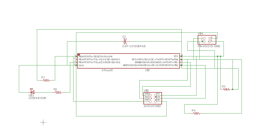
The tools I used for electronic production is eagle Cad to convert into board file into Gerber file & Cir-quid for circuit milling
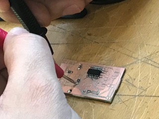
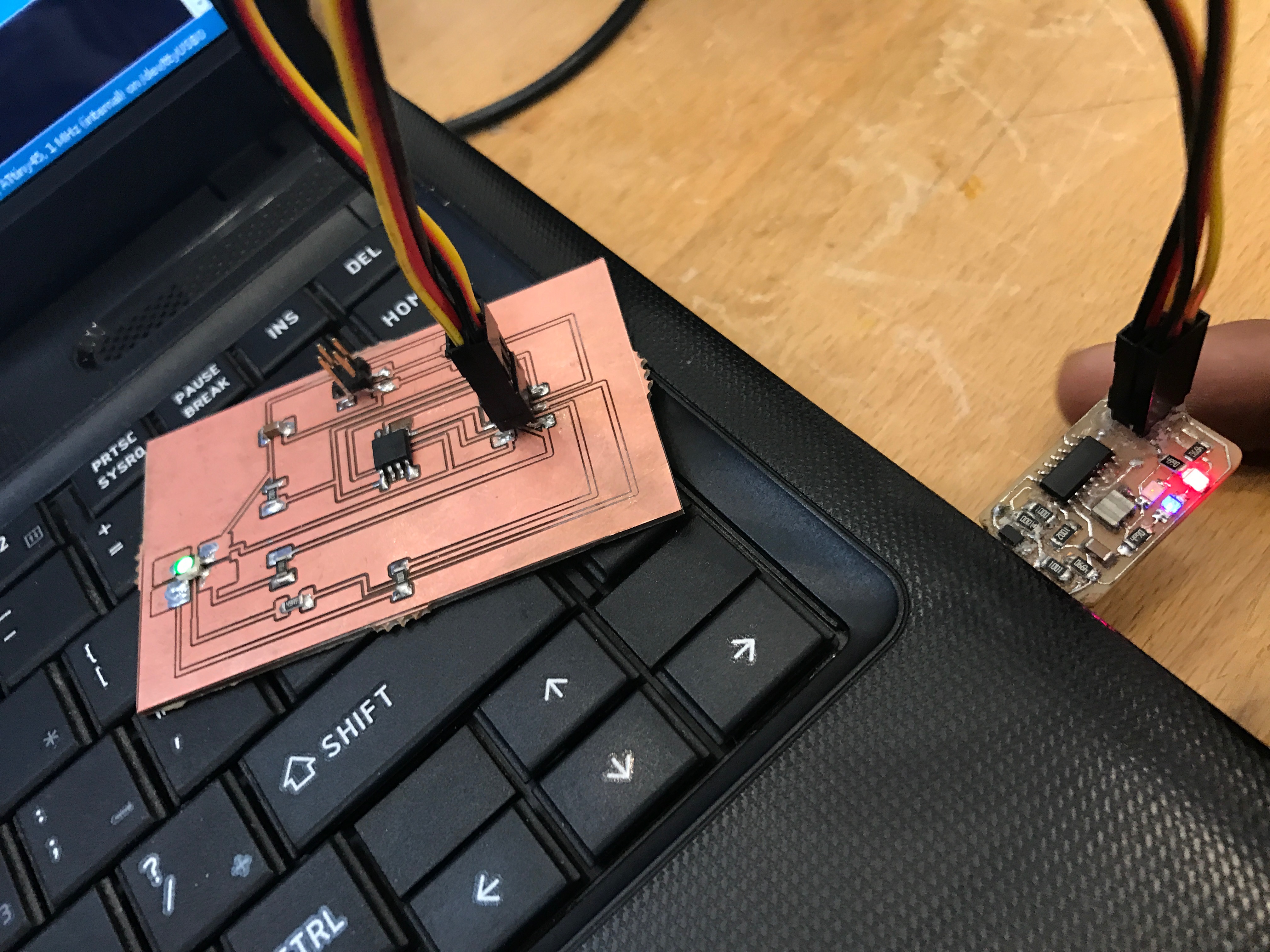
I downloaded David’s board from FABLAB website. My difficulty was soldering the part on the board. It was my first time in lifetime :) .
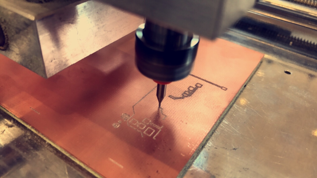
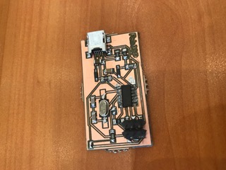
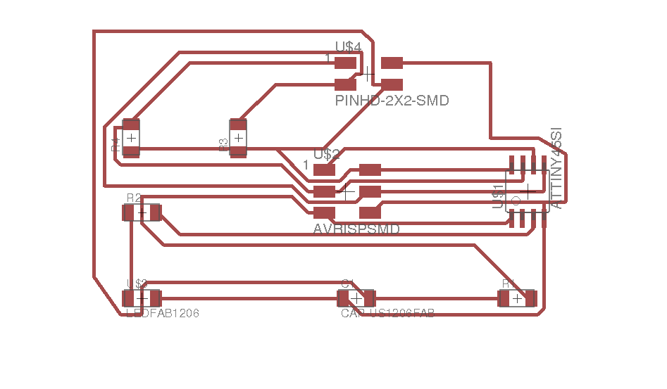
1- Millding Board circuit.
- I used Cir-Qwizard software & Cir-Qoid machine for the board cutting. Then i set the Y axis ,X axis & Z axis. Where the offset on Z axis is the vertical distance between the cutting edge of the milling cutter when the head is in zero position and on the surface of PCB.
Printing the Board
- First start Cir-Qwizard software and open the file
- Second select the dimension to 75x100 and click continue
- Put the copper board face up in Cir-Qoid machine and click continue
- Then select default tool and click continue.
- Select the Z offset ( where you can chick the depth by Z and x,y for the printing location ) after you select the location click continue
- Select the board then continue again ( Machine well start the process of printing )
- Then change the milling head on the machine for cutting step.
- Finally, Select the dots for cutting and click continue.
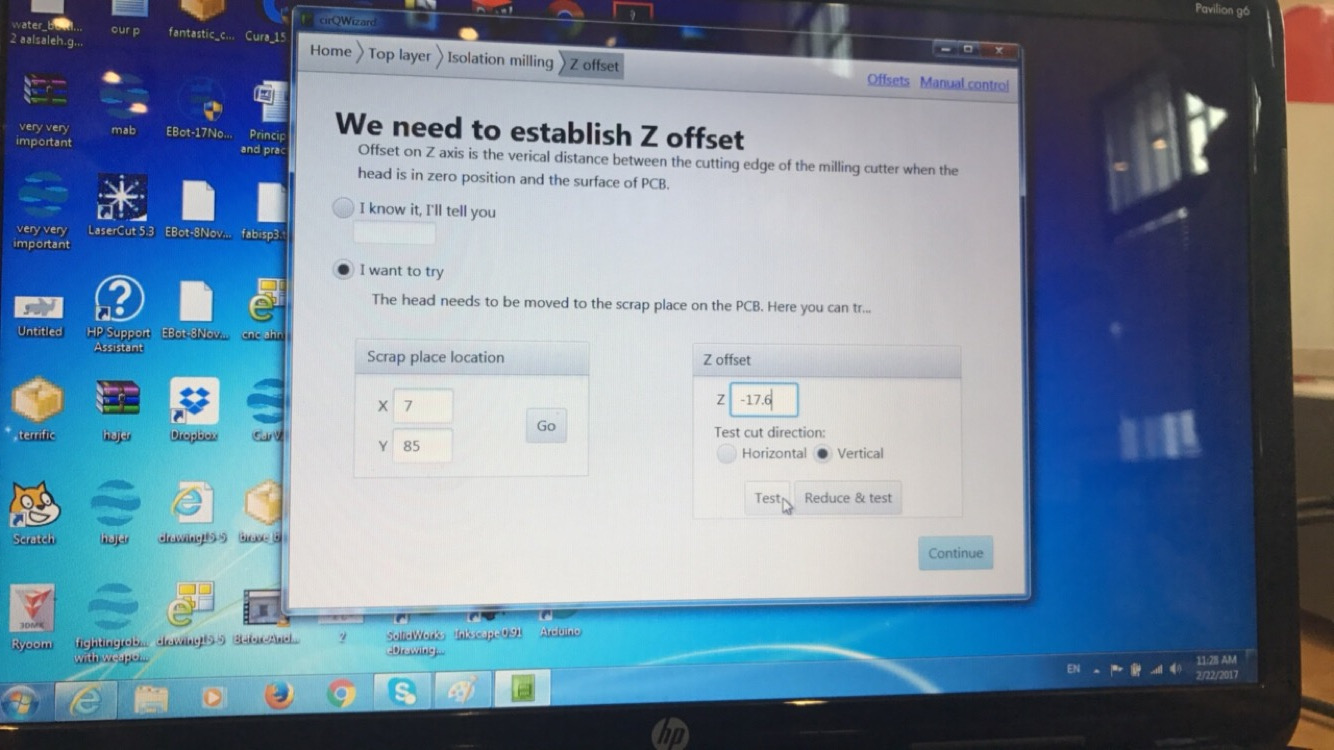
Sitting I used:
X: 7 Y:85 Z offset: -17.6
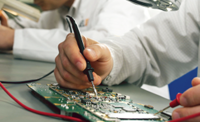
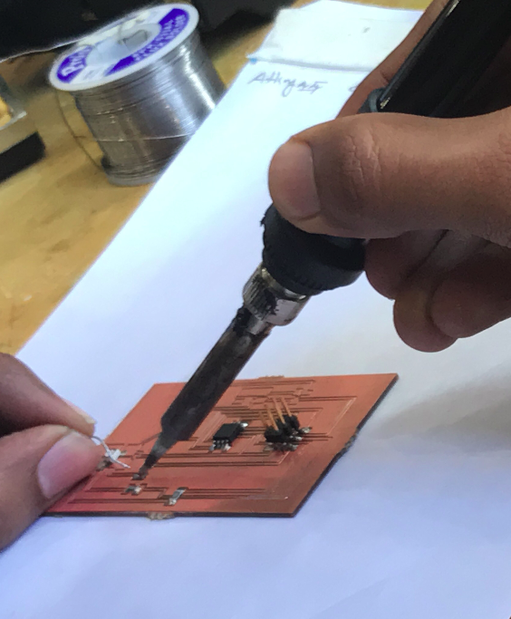
2- Soldering Elements on the board & testing it.
- after I finished from the board engrave, I start soldering I was not a SMD Solder expert so need some time on exploring several methods and so as to choose one .that suits me,So i choose to try all 3 methods i found and choose one like dropping lead in the place i wanted to solder before then place the component and just heat the lead drop and solder directly the other side.
3- Programing the board.
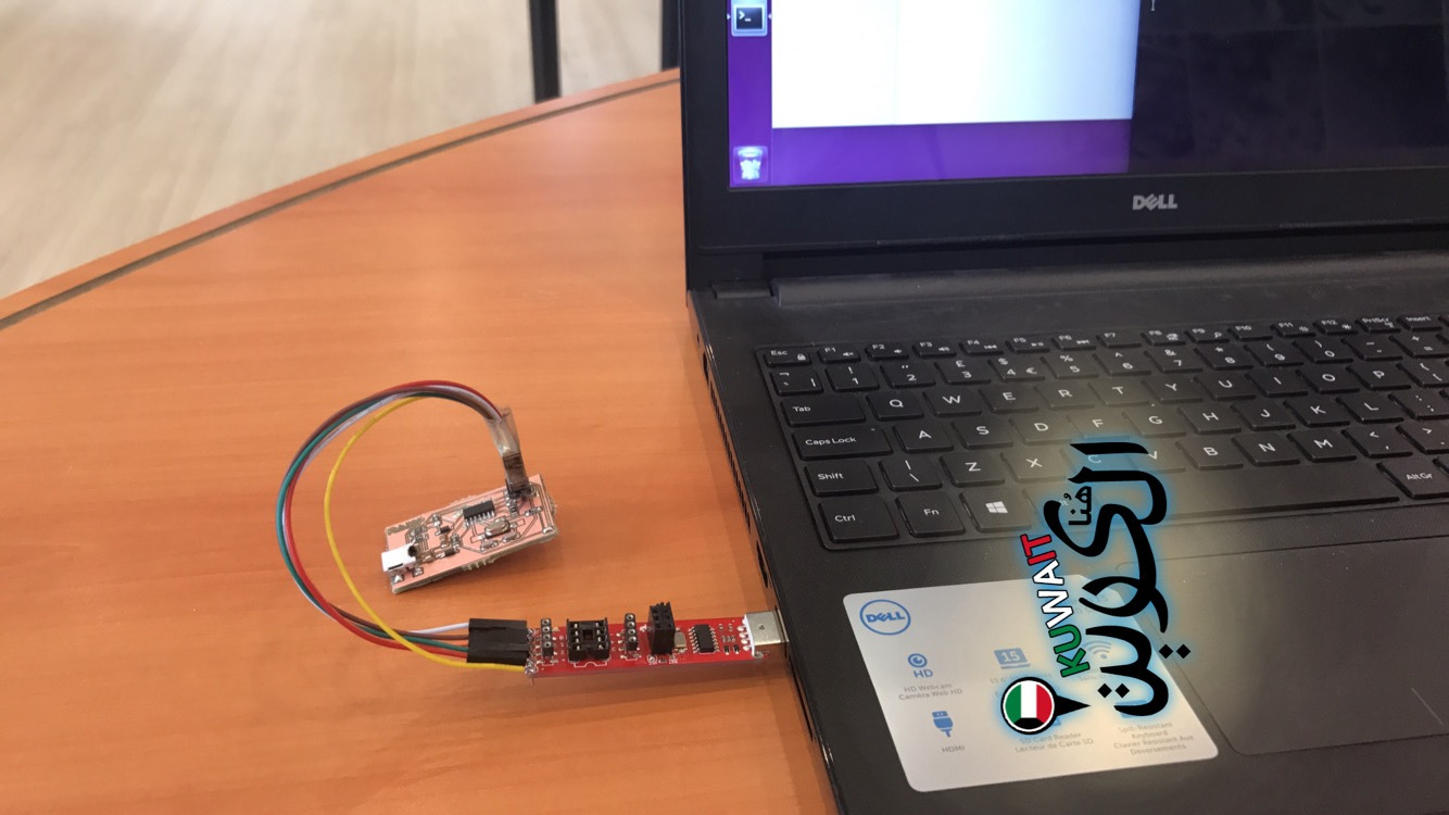
In order to program ISP I install some background progam. For installing that I use the following commands:
sudo apt-get install flex byacc bison gcc libusb-dev avrdude
sudo apt-get install gcc-avr
sudo apt-get install avr-libc
sudo apt-get install libc6-dev
- First I connect the ISP in my system through the AVR programmer, then I start he program.
I open the termnal and type the following commands
1-make clean
2-make hex
3-make fuse
4-make program
Board Sch FileBoard brd File
Fifth Week
3D Scanning and Printing.
INTRODUCTION
3D scanning is digital technology, which is neither destructive, nor does it involve any contact. By use of a laser light in form of a light, this technology captures objects as they are. Scanners, which use this 3D technology, do so by passing a laser light over the surface of that particular object, after which, they store the data in it in form of “point clouds”. The object is usually captures physically as it is in its 3 dimensions.3 D printing is known to be an efficient and fast method of establishing test in the prototype product development stage. The parts of these data are then transferred to the next stage, where the information is manufactured. However, this 3D technology has its own advantages and disadvantages. The following are some of these demerits and merits.
One of the main advantages of this technology is that it scans and prints documents very fast. Its design method of copying data from the scan object, and printing, is very fast and hence many copies can be produced within a short duration. Additionally, a document only undergoes only one step and then it’s printed, unlike other older technologies.
Disadvantages of 3D technology
3D machines and printers are generally expensive. Additionally, the materials used to make such machines, are various and limited. The machines are also small in size and therefore they can only create smaller print clouds. The printers of this kind have also led to unemployment of many people in companies which take advantage of cheap available human labor.
Testing
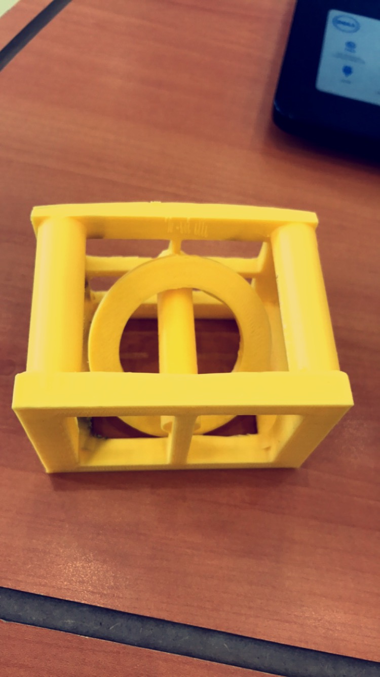
To check the printing accuracy me and the group printed the following design. And we discover that 3d printer does not print very small cuts and shapes.
Failure attempted
Designing
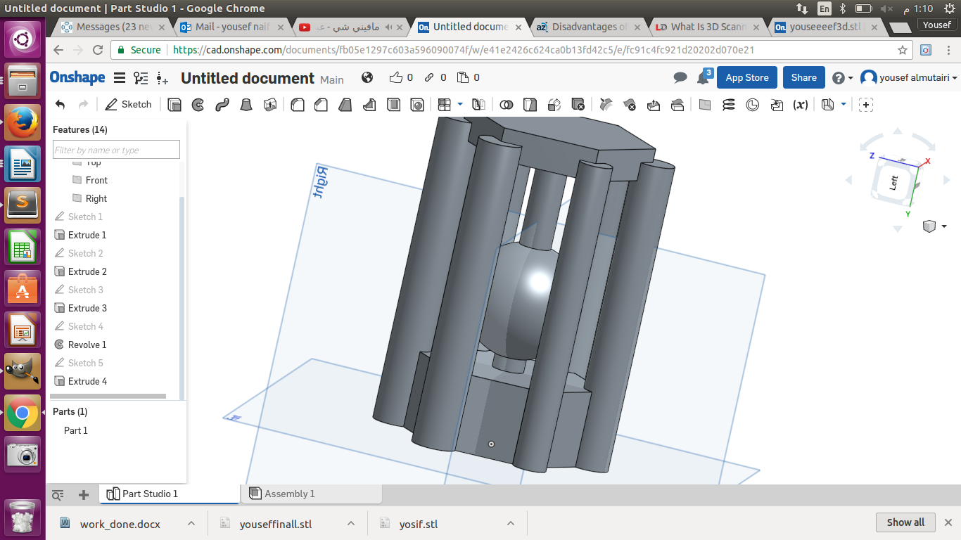
First I decide to great cylindrical shape and to add I ball inside it. Using On-shape I start to great the the base and then I add 6 columnist to support the edges. Then I add t circular cylinder shape and finally add the top of the shape to close on the circular cylinder shape inside it.
Printing
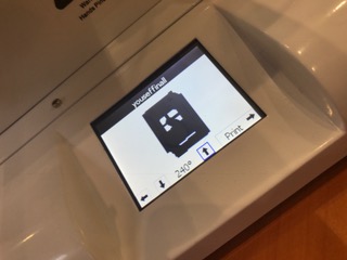
Second, I saved the 3D design as STL File and then i opened the file in REALvision application to adjusted the dimension, scalethen and to converted it to FCode extension, so I can print the shape out. I input the USB flash into the Wistek 2805 printer and set the printer heating to 240 to start printing the shape. When the printer finish the process after 2 hours i discover that my first attempted failed
Problem
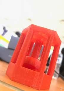
The mistake that I made is the that when created a ball inside the design I did let not let it touch the bottom of it, so when I printing the design the ball became an egg :). but I like it
Successful attempted
Designing
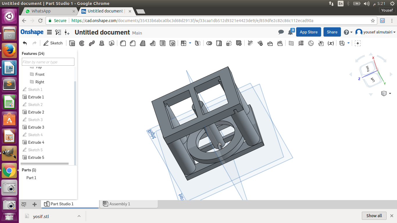
This time I decide to make a rectangle shape with 5 columnist 4 of them on the corners and one on the middle to support the top of the shape. And a circular cylinder inside it.
Problem Overcome
This time when I made the shape I made a small bridge between the bottom of the shape the circular cylinder so I can remove them later and make the circular cylinder loose.
 3D File
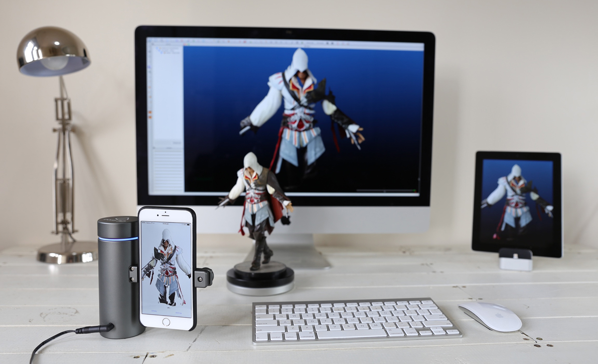
3D Scanning
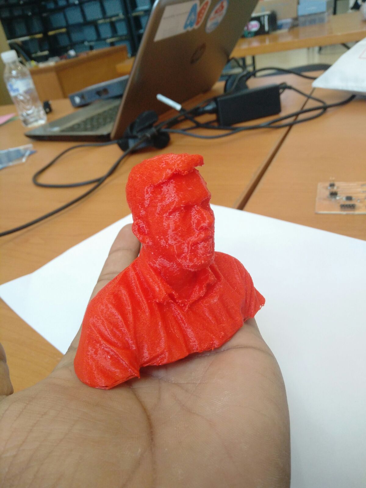
Using the Sense scanning device and software I scanned my friend Sanu and printed it out with the 3D printer. Scanning device are very easy and not complicated. Just downland the software and plug the Sense device into the laptop.
And this is the result of scanning
Sanu by yalmutairi on Sketchfab
3D printing my friend head :)
Sixth Week
Electronics Design.
Overview
The week's task involves revisiting the Hello Echo board that was previously handled but the only difference is the inclusion of Light Emitting Diode or LED. The specific type of LED is the one that has a switch to control the resistors. Another thing will be checking the performance of the board which is done by milling. If the board is found to have a malfunction, it is debugged by use of some automated test. Use of labs equipment can do the test with the aim of simulating the board.
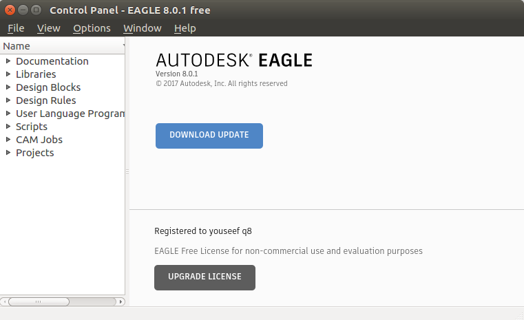
EAGLE
The word is an acronym that is used to represent Easily Applicable Graphical Layout Editor which is used to scheme electric systems. The device is always accompanied by PCB layout, auto-router, Schematic Capture and other computer aided products. EAGLE is widely used because of the ease to the clients. Another thing that makes it also be used a lot is the feature that enables engineering together with designs electronics. To use the app the user is required to install first. The application is registered under Autodesk license and therefore to successfully install the program one needs to open an account with EAGLE software to be allowed to use. Completion of the installing process the application requires the user to incorporate Fab and enjoy the product. Fab lab comprises extensive of electronic inventories, and all are added to EAGLE. That is why it is important to import Fab to the EAGLE. All one may decide to customize electronic devices by use of footprints in different EAGLE tools.
Microcontroller
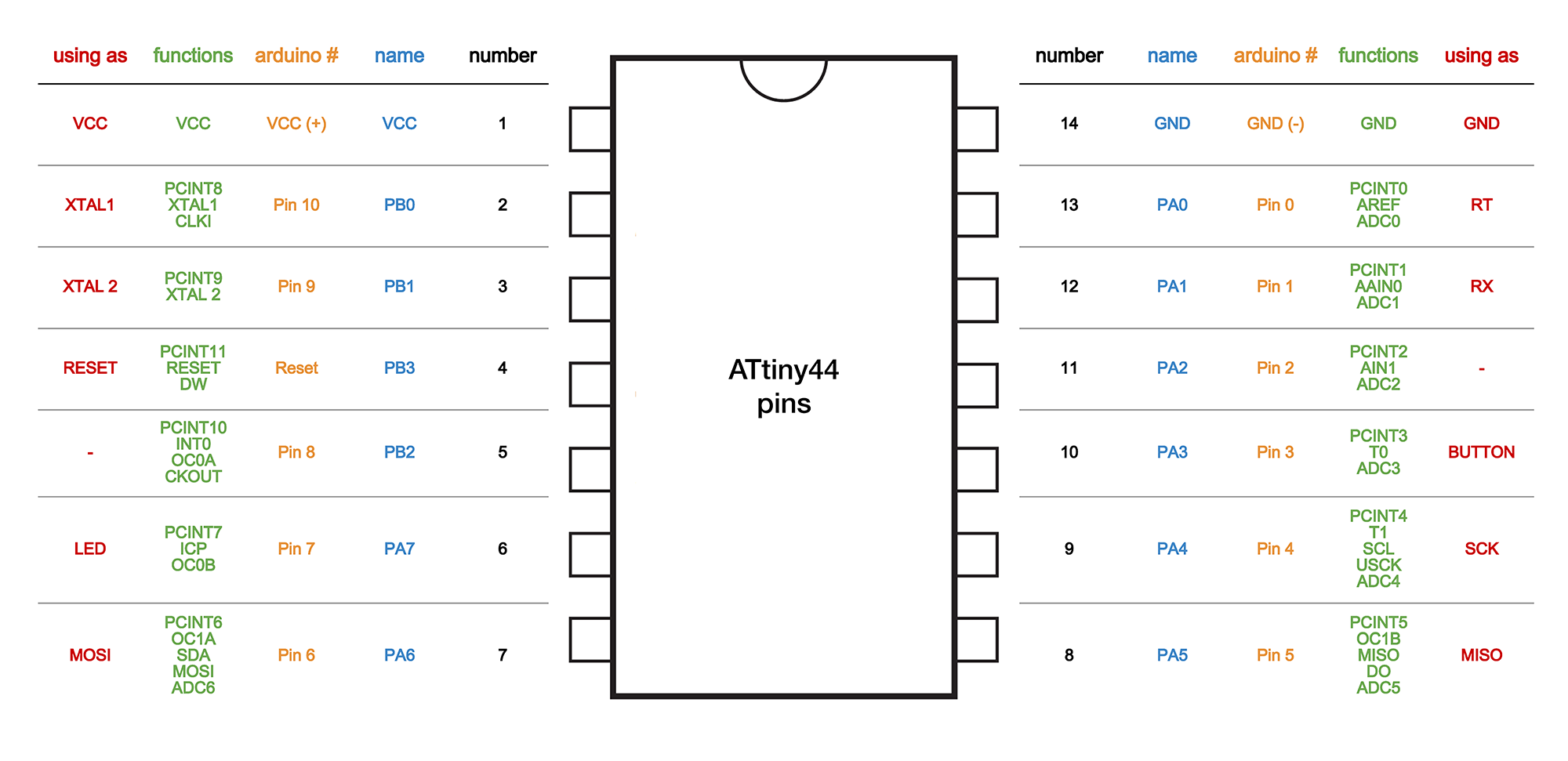
This is a device that works with the help of microprocessor to study the purpose of ATtiny44 microcontroller data. The data still has more information regarding the description of a microcontroller such as a pin configuration among others.
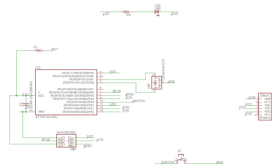
Schematics
First, Before redrawing the board I downloaded the FAB.lbr so I can use it in eagle. To open the FAB.lbr on eagle you go to ( Library → USE → then select the FAB.lbr file and click open ).second, adding the component of my circuit board and connecting them together. There are differents tools to do that, one is label tool and the other is the net tool. For me I like the label tool as I only rename the component and rename the other components that I want to connect with it. Net tool is just drawing lines to connect the component you need together.
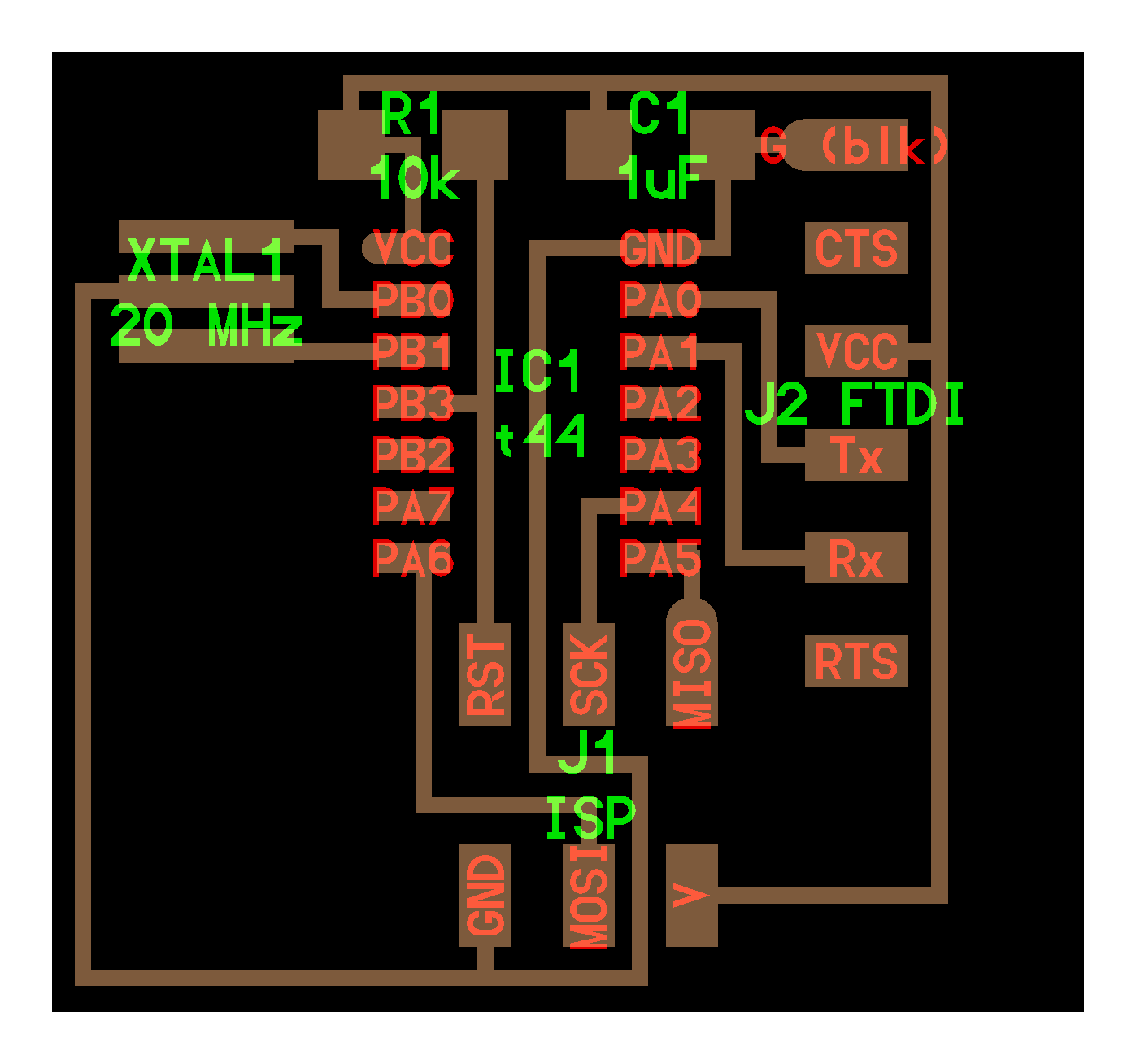
Components Used: ( Attiny 44 - AVR ISP SMD - LED 1 - Resistor 100 ohm - 6mm tact Switch - Resonator 20 mhz - Capacitor 1 UF - Resistor 10 K - FTDI SMD Header )
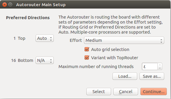
Routing
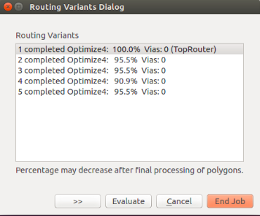
After I finish from the schematics I need to rout my circuit board, and that done by auto-routing. To auto-rout click on the symbol in the dawn left corner and follow the following Picture. Then press countinue.
Then I got the following window and I choose the 100% routing.
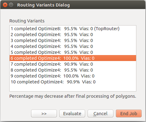
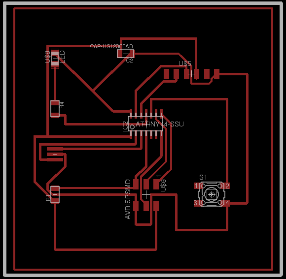
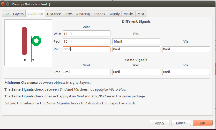
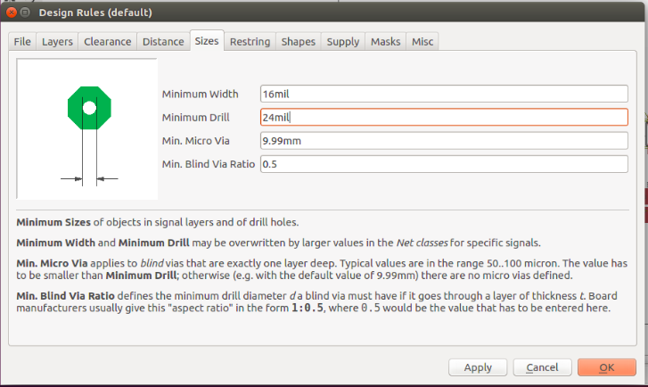
After that go to edit then Design rules to increase the rout width.
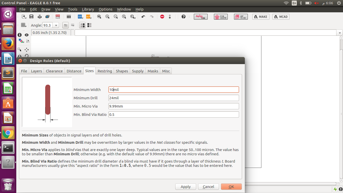
Printing
After am done from schematics and routing now it is the time to printing my board. To do so, I saved the file as .brd then converted it to cmp using eagle. Steps as follwing.
- File → Cam processor → File → open → Jop then select
file named cqw-gerb274x.cam → Process job
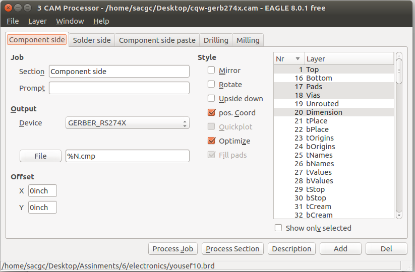
After that I used Cir-Qwizard software & Cir-Qoid machine for the board cutting. (steps mentioned in week4).
Sch File Brd File
Seventh week
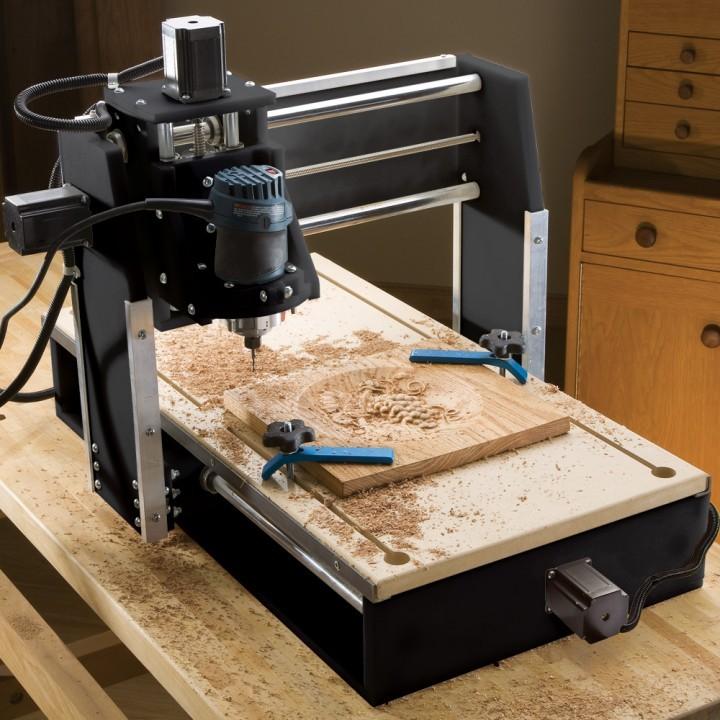
CNC Machining
The process of controlling machine tools by using computers during the manufacturing process is called CNC machining. CNC is an acronym for Computer Numerical Control. CNC machines does not allow all tools to be controlled. However, there are some that can be controlled and they include tools like mills, grinders, lathes and routers.
The CNC machining process begins with the creation of an object’s Computer Aided Design or CAD file. After the design of a CAD file for a given object, a software for Computer Aided Manufacturing or CAM is used for the conversion of the CAD file that is in 3D to a several codes that a machine can understand and process. The CNC machining uses a programming language of its own that is called G-code. The G-code language is helpful in controlling manufacturing features like coordination, speeds, feed rates and positioning. The CNC machining and G-code can be used to establish an exact and accurate velocity and positioning features during construction.
CNC History
Computer Numerical Control or CNC in short is a technique whose history can be traced back to the Numerical Control or NC technique. NC is a traditional process in manufacturing that involved control of various tools. The NC process did not use computers. However, with the invention and modern technology, the NC process was extended to use computers to control the manufacturing tools. This outgrowth led to a process called Computer Numerical Control. The CNC improved speeds, efficiency and automation in the manufacturing processes.
Materials Used
A CNC machine can use nearly any material. The only determinant on the materials used is the application. However, there are common materials used that include titanium, aluminum, steel, brass and coppers. Non-metallic materials such as fiberglass, wood, foam and plastics can be used as well.
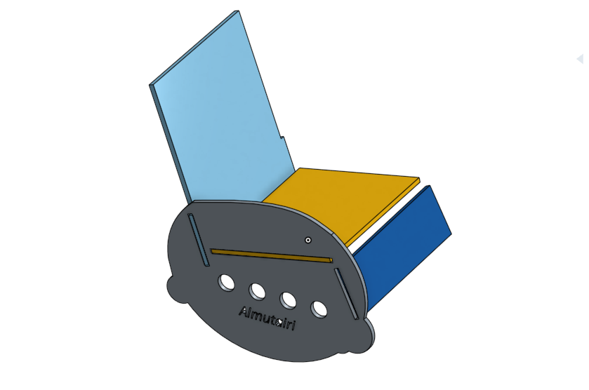
My plan is to build rocking chair to but it in our living room for my father, using Onshape am going to make the chair 3D design and then to cut the part using the CNC machine, and assembling the parts to get the final project done, Finally at home am going to coat the chair with sponge and fabric to make it very comfortable for my Hero.
Tools & Material used:
software:
- Onshape
- Artcam
hardware:
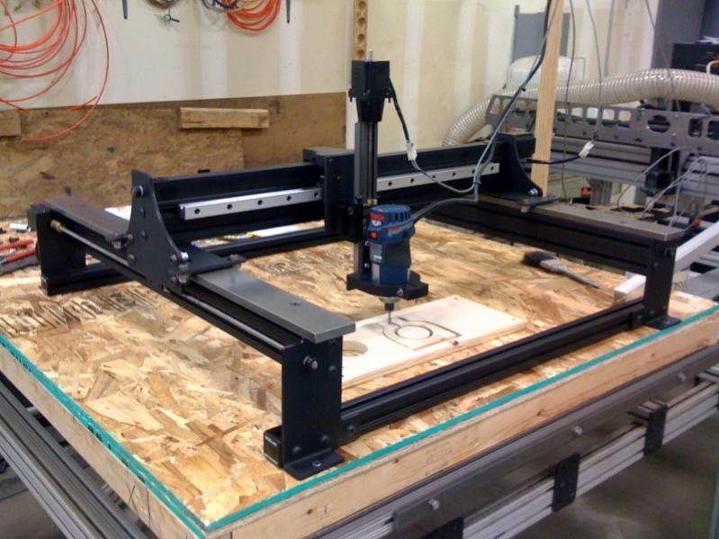
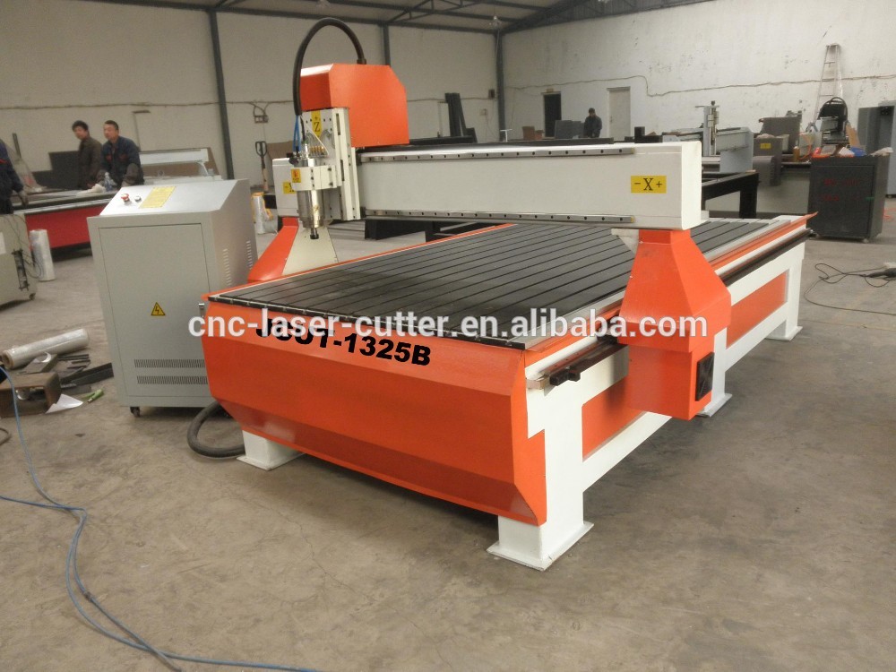
- CNC Machine (JCUT-1325B)
Material:
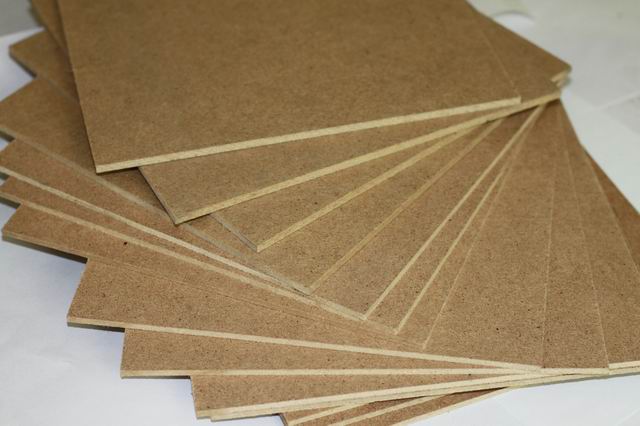
-Wood Plate (MDF) 18MM thickness
Implementation
1- Design Making (Onshape)
First, using Onshape software I create the rocking chair parts, they where 5 parts. 2 rocking parts each one represent one side of the leg and the arm for both sides left and right, the back of the chair I made it little bit long so I can later on add neck and head sponge supporter, The seat also I made it wide so when I coat the chair it is going to be little bit narrow, and at last the foot supporter part. When creating the chair design I take in consideration the wholes that am making on the parts to be 18MM as the wood plate thickness is 18MM to get the parts fits together when assembling them.Finally, i save the file as DXF to convert ot later on to PLT file using Artcam software.
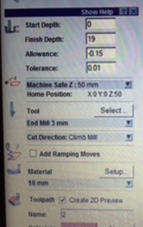
 2- Artcam
First, using Onshape software I create the rocking chair parts, they where 5 parts. 2 rocking parts each one represent one side of the leg and the arm for both sides left and right, the back of the chair I made it little bit long so I can later on add neck and head sponge supporter, The seat also I made it wide so when I coat the chair it is going to be little bit narrow, and at last the foot supporter part. When creating the chair design I take in consideration the wholes that am making on the parts to be 18MM as the wood plate thickness is 18MM to get the parts fits together when assembling them.Finally, i save the file as DXF to convert ot later on to PLT file using Artcam software.
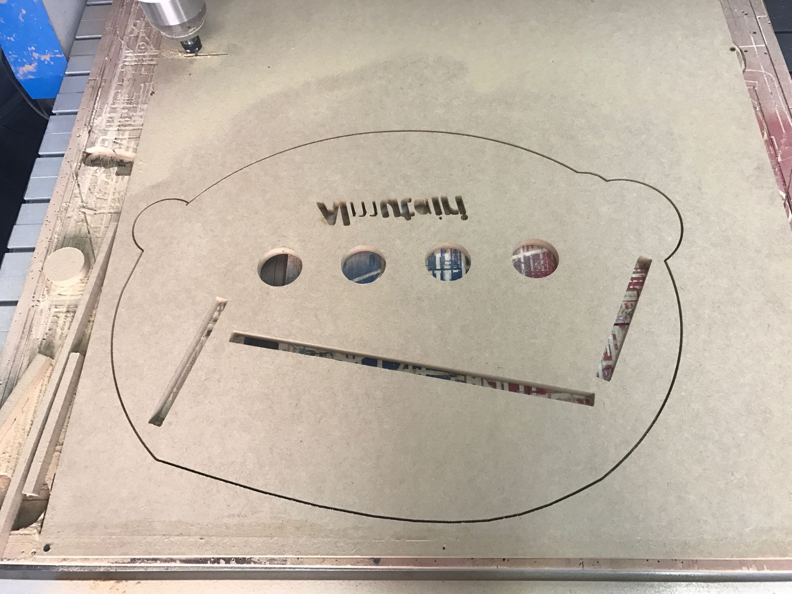
3- CNC Cutting Machine
For the CNC cutting machine using controller to set the home position,set and control the x-axis , y-axis and z-axis , also it is used to import the PLT files
CNC Machine
After converting our file to PLT file using Artcam program. Export the file to USD flash and plug it into the Controller → set the home position by moving X,Y and Z coordinates → select the → file then setup the speed → and finally run the file.
Keep in mind to fix the wooden sheet with screws so the sheet do not move when the machine start cutting, and make sure to not set the home postion on top of any screwe. Tutorial notes to set the speed of the machine to 3000.00.
 Design File
Embedded Programming
Data Sheet
The concept refers to just how the pins are repeating and the manner in which that they are configured. To program a microcontroller pins must be aligned in a certain order that obeys the configuration otherwise nothing can be achieved. Failure to follow the order nothing can be achieved during the process.
ATtiny44 pin configuration
Programming or burning a microcontroller is.
The process entails moving of program from compiler to microcontroller. The program that is contained by the microcontroller is simply the assembling language, and the compiler helps in generating a hex file. The hex file contains a language that is understood by the machine and therefore it can comprehend the instructions. The microcontroller can work but to perform another task with the help of the compiler, it can implement machine language. In other words, the compiler makes the microcontroller to function efficiently.
Programing a microcontroller
To conduct a successful programming the programmer needs a hardware that is going to be dedicated to the software. The software is intended to read the hex file that is either on laptop or PC. After successfully reading the hex file and establishing its contents transfer is done and microcontroller burned.
Connecting the programmer and the microcontroller
So far microcontroller has been created as a device that comprises of six pins. The pins are contained in the ISP cable which is used to connect both the microcontroller and the programmer. The programmer establishes the six pin ISP cable to conduct any operation that they are entitled to fulfill.
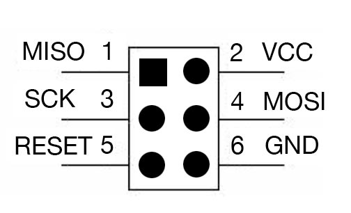
- Vcc: providing voltage to the circuit
- GND: grounding the circuit board
- MOSI: master Data output, Slave Data input
- MISO is master Data input, Slave Data output
- SCK: Universal Serial Interface Clock
- RESET: an external Reset input is active low and enabled by unprogramming
Board Schematic
Finall Board
Programing my board.
In order to start programing the ATtiny to make the led in the board blink, First I downloaded Arduino IDE. And then I add the Attiny board manager, instruction here.
Aurdino blinkig program
/*Blinking ledYousef AlutairiFabAcademy 2017StudentFablabKuwait*/void setup(){// initialize digital pin 13 as an output.pinMode(7, OUTPUT);pinMode(8, OUTPUT);}// the loop function runs over and over again forevervoid loop(){digitalWrite(7, HIGH); // turn the LED on (HIGH is the voltage level)delay(50); // wait for 50 seconddigitalWrite(7, LOW); // turn the LED off by making the voltage LOWdelay(50); // wait for 50 seconddigitalWrite(7, HIGH); // turn the LED on (HIGH is the voltage level)delay(50); // wait for 50 seconddigitalWrite(7, LOW); // turn the LED off by making the voltage LOWdelay(50);digitalWrite(8, HIGH); // turn the LED on (HIGH is the voltage level)delay(50); // wait for 50 seconddigitalWrite(8, LOW); // turn the LED off by making the voltage LOWdelay(50); // wait for a seconddigitalWrite(8, HIGH); // turn the LED on (HIGH is the voltage level)delay(50); // wait for 50 seconddigitalWrite(8, LOW); // turn the LED off by making the voltage LOWdelay(50);}
Aurdino LED and SWITCH program
void setup() {// initialize digital pin 13 as an output.pinMode(7, OUTPUT);pinMode(8, OUTPUT);pinMode(2,INPUT);}// the loop function runs over and over again forevervoid loop() {if(digitalRead(2) == LOW){digitalWrite(7, HIGH); // turn the LED on (HIGH is the voltage level)delay(50); // wait for 50 seconddigitalWrite(7, LOW); // turn the LED off by making the voltage LOWdelay(50); // wait for 50 seconddigitalWrite(7, HIGH); // turn the LED on (HIGH is the voltage level)delay(50); // wait for 50 seconddigitalWrite(7, LOW); // turn the LED off by making the voltage LOWdelay(50);digitalWrite(8, HIGH); // turn the LED on (HIGH is the voltage level)delay(50); // wait for 50 seconddigitalWrite(8, LOW); // turn the LED off by making the voltage LOWdelay(50); // wait for 50 seconddigitalWrite(8, HIGH); // turn the LED on (HIGH is the voltage level)delay(50); // wait for 50 seconddigitalWrite(8, LOW); // turn the LED off by making the voltage LOWdelay(50);}else{digitalWrite(7,LOW);digitalWrite(8,LOW);}}
Board Sch File
Board brd File
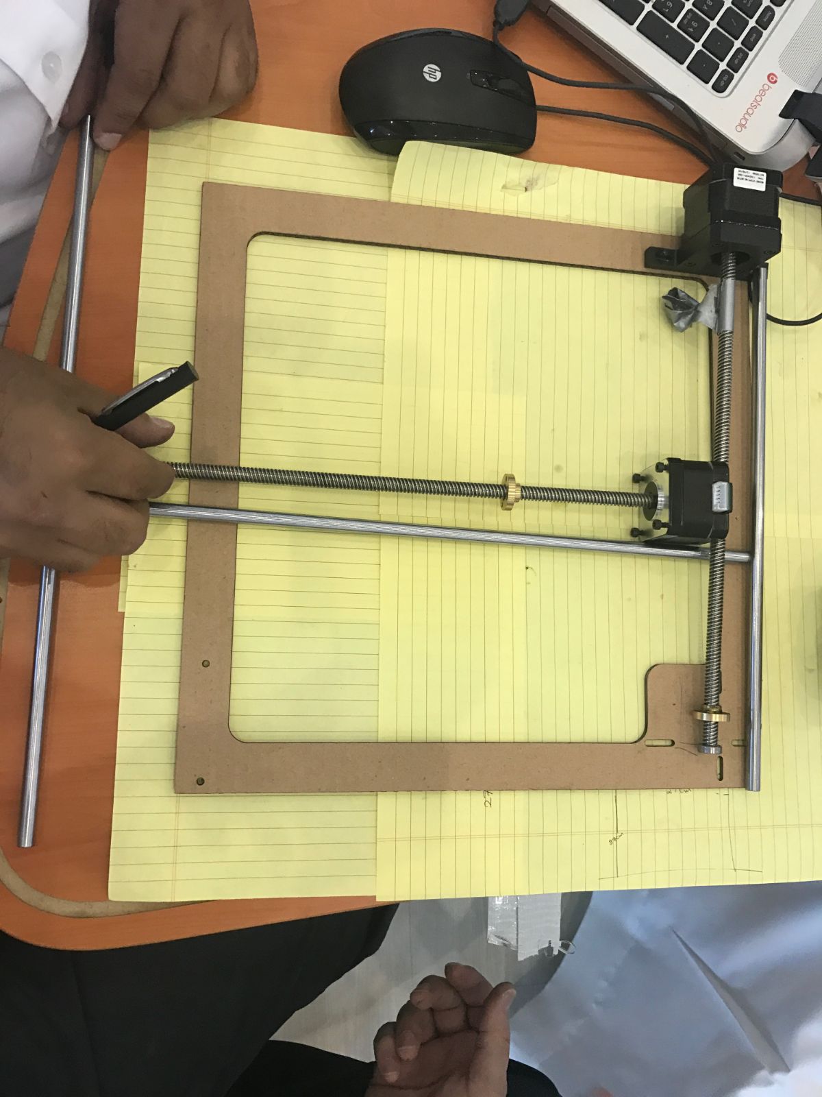
Group Project – Find Me
Group Project – Find Me
For this week we are going to build a machine as a Team. So we gathered and we start to brain storming to come up with our plan. First, we discussed about what we are going to build and decided to build a CNC Machine to help us finding the parts and components we need inside the drawer by typing the name of the parts and then the LED light well move to the required drawer.
Second, we arrange to dived our group to 6 teams which are the following, Where I was with the Printing & Laser Cutting Team:
Group Project Find Me
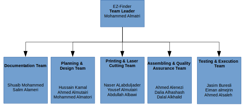 - Documentation Team: Documenting the process of the project.
- Planning & Design Team: Planning process of the whole project, designing the project and all the pieces required to complete the design.
- Printing & Laser Cutting Team: Assure that the process flows smoothly from the design team back to their team.
- Assembling Quality Assurance Team: Putting all the pieces together after the cutting process, assuring the design went smoothly and the printing and cutting is effect.
- Testing & Execution Team: The final step of the process which is the testing & execution.
Our Team role:
1- Follow up with the design team to make sure that the process flows smoothly.
2- quality assurance check-up after design is completed.
3- If any comments or error occurred in this meeting, our team will send the project back to the design team to make the required change
4- Print the Logo of the product in both 3D printer and sticker printer.
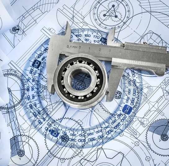
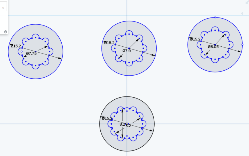
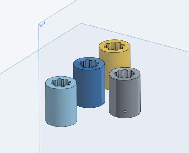
5- Design the bearing
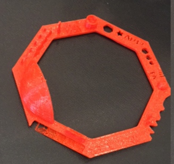
Bearing Design
The bearing is required to assure that the friction of the mechanical movement is efficient in the movement of the motor. The design started with different type of radius until we assured that the radius fits the Rod. 3 pieces is required here is a top vie of the bearing pieces required in the design stage. this is an extruded view of the bearing pieces that allows friction in the Rods to move smoothly as described above.
Contribution
First I help with planing of our team, designing and printing of the bearings. I suggested to make multiple bearing with different size in order to try them in our project and see which size fits the rail way of the stepper motor. Also I helped with the mechanical design and change a little in it.
Output Devices
- Assignment:
- Add an output device to a micro controller board you've designed and program it to do something
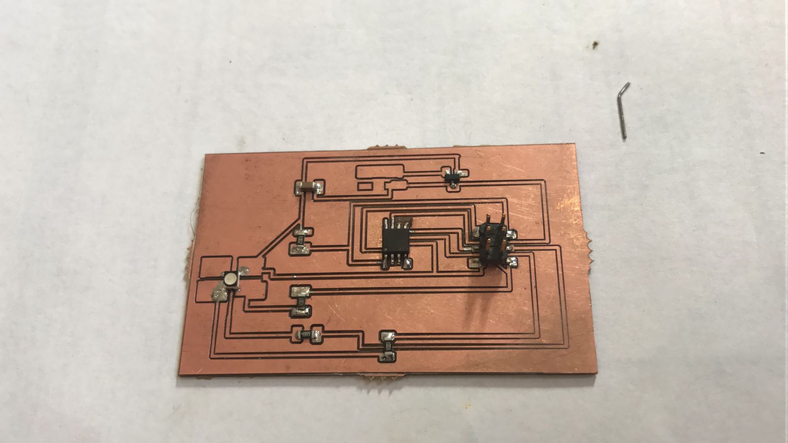
- My Work
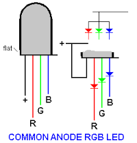
For this week, am going to add an output device to a micro controller board which I designed, where I added RGB LED light as an output. RGB light means “red, blue and green LEDs. RGB LED products combine these three colors to produce over 16 million hues of light. Note that not all colors are possible. Some colors are “outside” the triangle formed by the RGB LEDs. Also, pigment colors such as brown or pink are difficult, or impossible, to achieve.”.
Reference
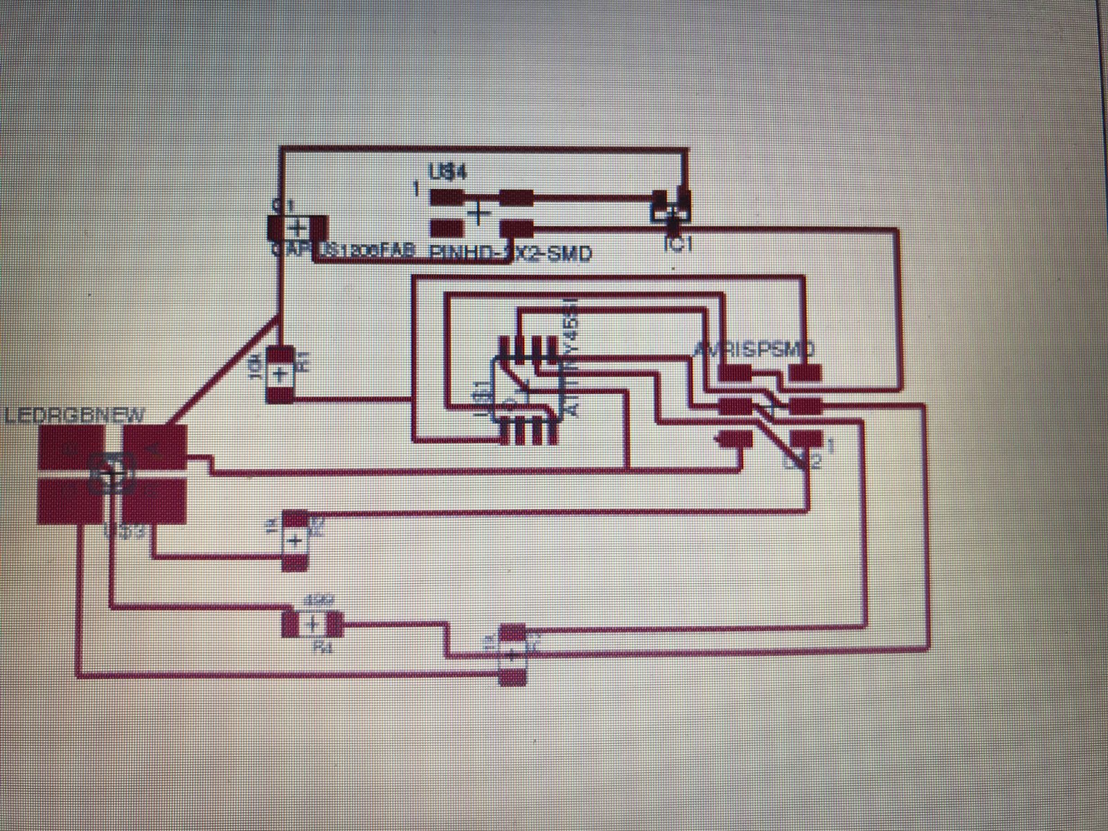
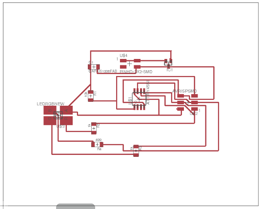
- Design
For the Circuit board design as always I used eagle cad do my schematic design. I used Attiny45 and connected it to the RGB LED. Red, Green and Blue color are connected to the pins PB1, PB0 and PB2 respectively.

- And here is my schematic design.
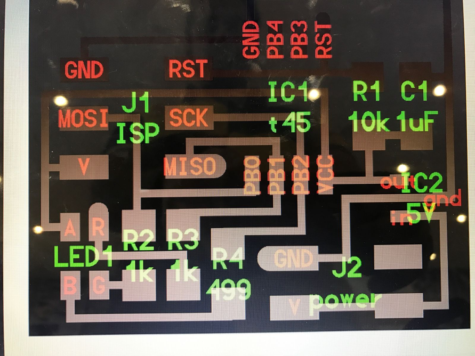
- Rooting
For the rooting I always use the auto-rooting tool and then I made some editing for the width of some traces and move some other because some traces are very close to each other and that might cause some shorts in the board while soldering it.
- Programming :
The code I used to program my board.
int redPin = 1;
int greenPin = 0;
int bluePin = 2;
//uncomment this line if using a Common Anode LED
//#define COMMON_ANODE
void setup()
{
pinMode(redPin, OUTPUT);
pinMode(greenPin, OUTPUT);
pinMode(bluePin, OUTPUT);
}
void loop()
{
setColor(255, 0, 0); // red
delay(1000);
setColor(0, 255, 0); // green
delay(1000);
setColor(0, 0, 255); // blue
delay(1000);
setColor(255, 255, 0); // yellow
delay(1000);
setColor(80, 0, 80); // purple
delay(1000);
setColor(0, 255, 255); // aqua
delay(1000);
}
void setColor(int red, int green, int blue)
{
#ifdef COMMON_ANODE
red = 255 - red;
green = 255 - green;
blue = 255 - blue;
#endif
analogWrite(redPin, red);
analogWrite(greenPin, green);
analogWrite(bluePin, blue);
}
Brd File Cmp File
Group Project – Find Me
Group Project – Find Me
For this week we are going to build a machine as a Team. So we gathered and we start to brain storming to come up with our plan. First, we discussed about what we are going to build and decided to build a CNC Machine to help us finding the parts and components we need inside the drawer by typing the name of the parts and then the LED light well move to the required drawer.
Second, we arrange to dived our group to 6 teams which are the following, Where I was with the Printing & Laser Cutting Team:
Group Project Find Me
- Documentation Team: Documenting the process of the project.
- Planning & Design Team: Planning process of the whole project, designing the project and all the pieces required to complete the design.
- Printing & Laser Cutting Team: Assure that the process flows smoothly from the design team back to their team.
- Assembling Quality Assurance Team: Putting all the pieces together after the cutting process, assuring the design went smoothly and the printing and cutting is effect.
- Testing & Execution Team: The final step of the process which is the testing & execution.
Our Team role:
1- Follow up with the design team to make sure that the process flows smoothly.
2- quality assurance check-up after design is completed.
3- If any comments or error occurred in this meeting, our team will send the project back to the design team to make the required change
4- Print the Logo of the product in both 3D printer and sticker printer.
5- Design the bearing
Bearing Design
The bearing is required to assure that the friction of the mechanical movement is efficient in the movement of the motor. The design started with different type of radius until we assured that the radius fits the Rod. 3 pieces is required here is a top vie of the bearing pieces required in the design stage. this is an extruded view of the bearing pieces that allows friction in the Rods to move smoothly as described above.
Contribution
First I help with planing of our team, designing and printing of the bearings. I suggested to make multiple bearing with different size in order to try them in our project and see which size fits the rail way of the stepper motor. Also I helped with the mechanical design and change a little in it.
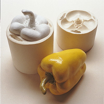
Molding and Casting
Introduction
Molding
According to Jones & Mullen, 1971, molding can be referred to as the shaping of a liquid material into a desired shape by using a hollow material known as a mold. The desired shape is the final shape that must be achieved out of the whole process hence the hollow material used must produce the shape of the mold required. A mold on the other end is a hollow container that is used to give shape to a hot material that is in molten state. When the material cools down and relaxes, it takes the required shape e.g. wax, plastic, steel or metal. The process of pouring the molten hot material into the mold is referred to as casting. It is common in industries that deal with smelting of metals like car manufacturing and electronics manufacture (Jones & Mullen, 1971).
Casting
Types of casting include permanent casting, continuous and sand casting. Permanent casting is commonly used in manufacturing industries like steel and iron manufacture. Molds got from permanent casting have a limited life span before they begin to wear out but it can be refinished (Jones, & Mullen, 1971). This type of casting is expensive compared to the other types of casting. Continuous casting is used in high volume and continuous production of mental sections. It is used mainly to lower costs associated with production of a standard product to increase the final product quality.
Assignment: Design a 3D mould, machine it, and cast parts from it.
Design a 3D mould
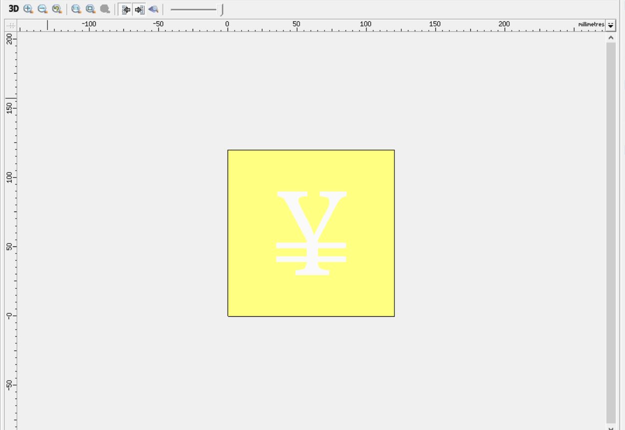
For this week am going to design my 3D shape on TinkerCad, am going to do my first letter Y to mold.
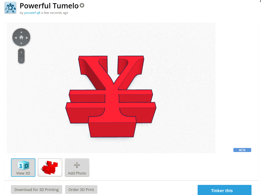
Atfer finishing from the design I save my file as STL.
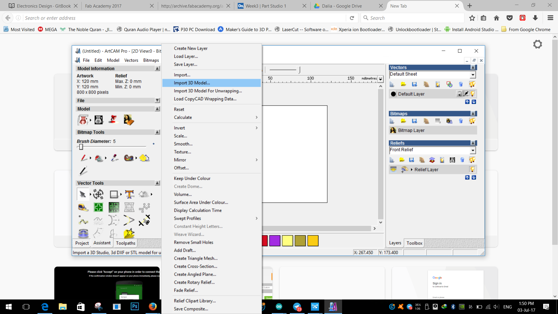
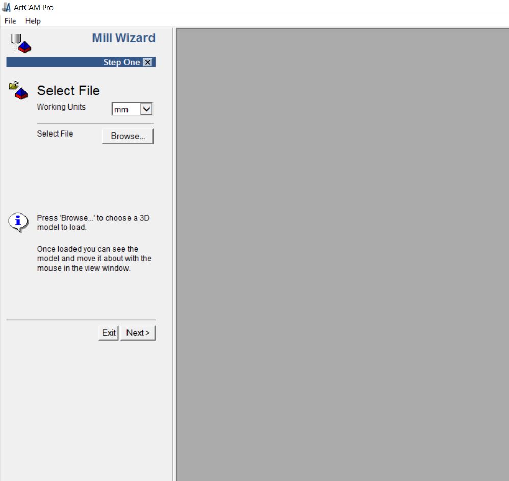
Artcam
Next step is to do the modifcation and convert the STL file to PLT file so the CNC Machine can read it.
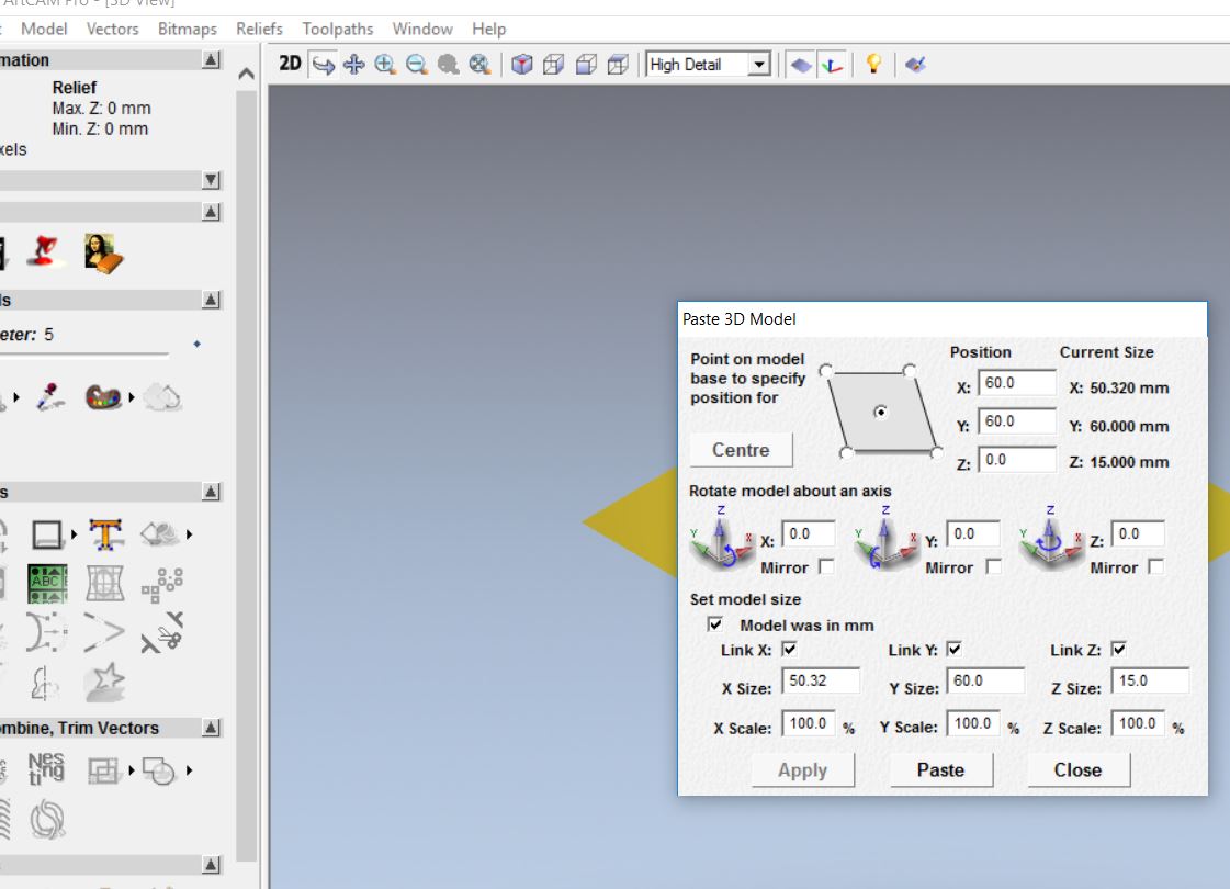
3D file importing
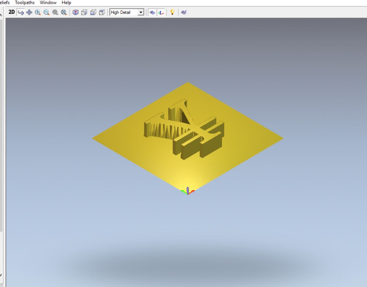
Pasting the model incentreof material.JPG
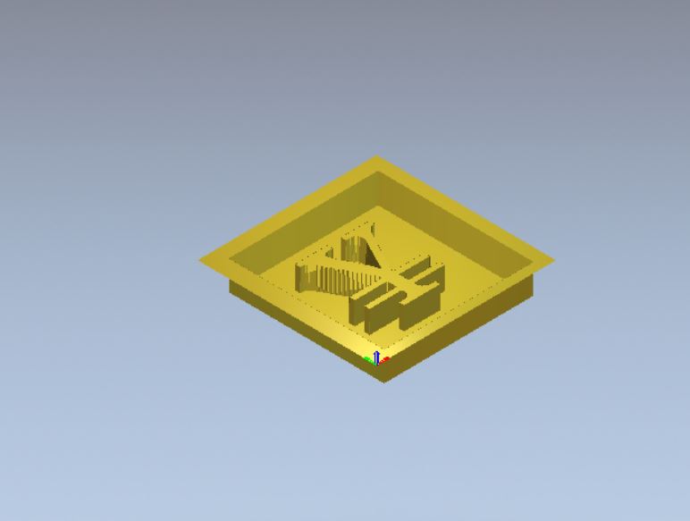
Material 3d view
Grey scale image converting for 2D
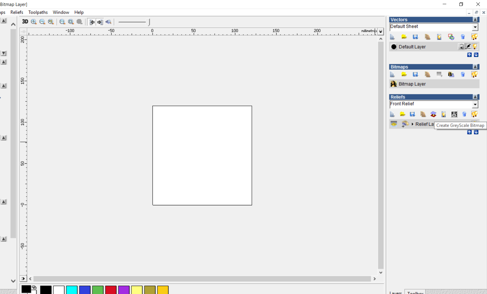
Greyscaled file
Zero reseting and substracting
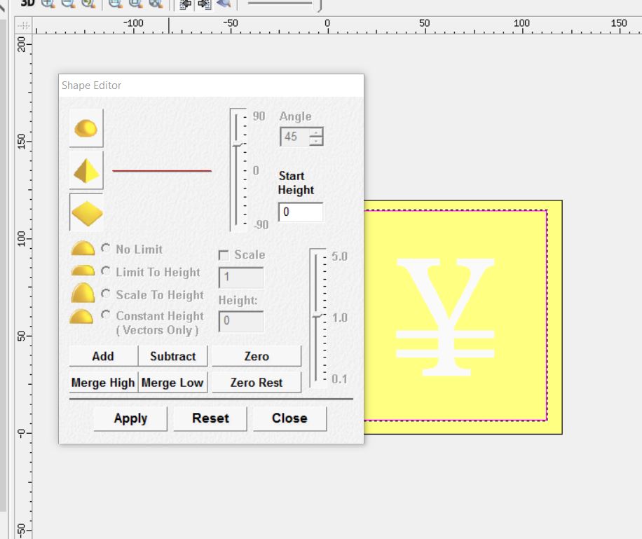
3D view of zero resetting
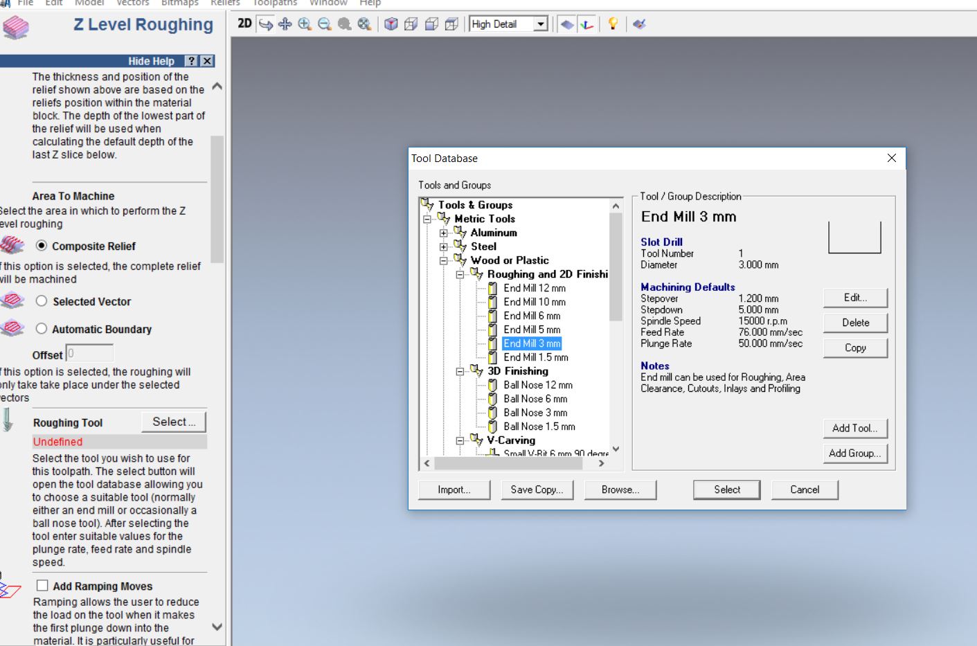
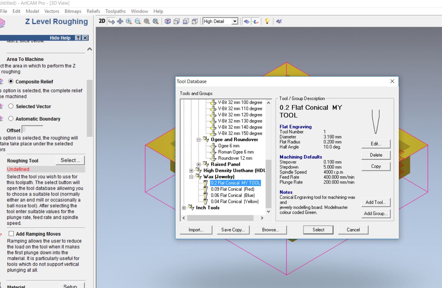
Z level roughing tool path generation
Z level smooth finishing tool path generation
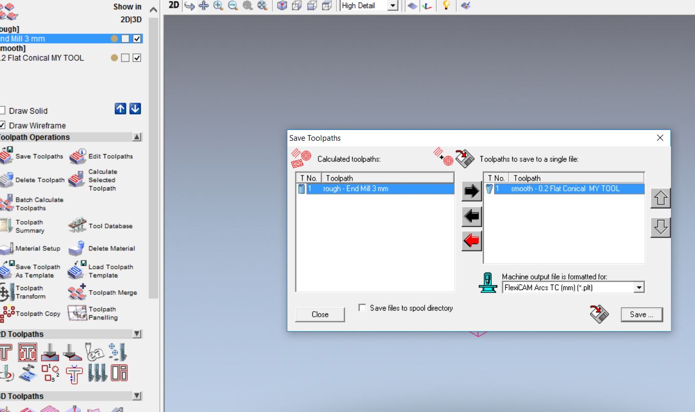
File generation
Machine it
For this step I got the wax from the lab inventory and fixed it on the CNC machine for milling my design. (CNC machine steps mentioned in week 7)
Molding :
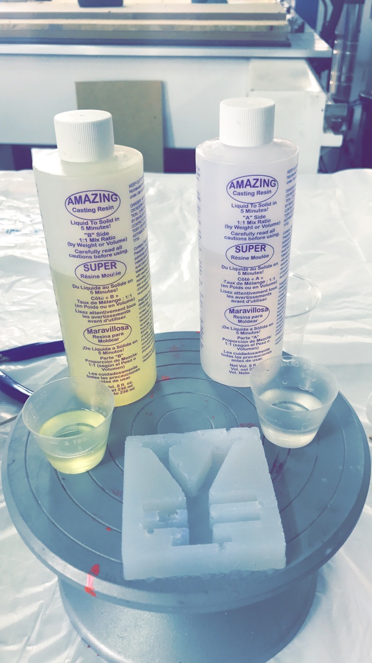
For this step we need to have 2 transparent cups, gloves and a tool to mix the solvents together. I used RTV2 Silicon Rubber. Solvent A RTV1510-A and Solvent B RTV1510-B where I mix them to be 50% Solvent A and 50% Solvent B.
First I measured the quantity that I need from solvent A and B by adding water in the milled wax, and then divided it in the cups.
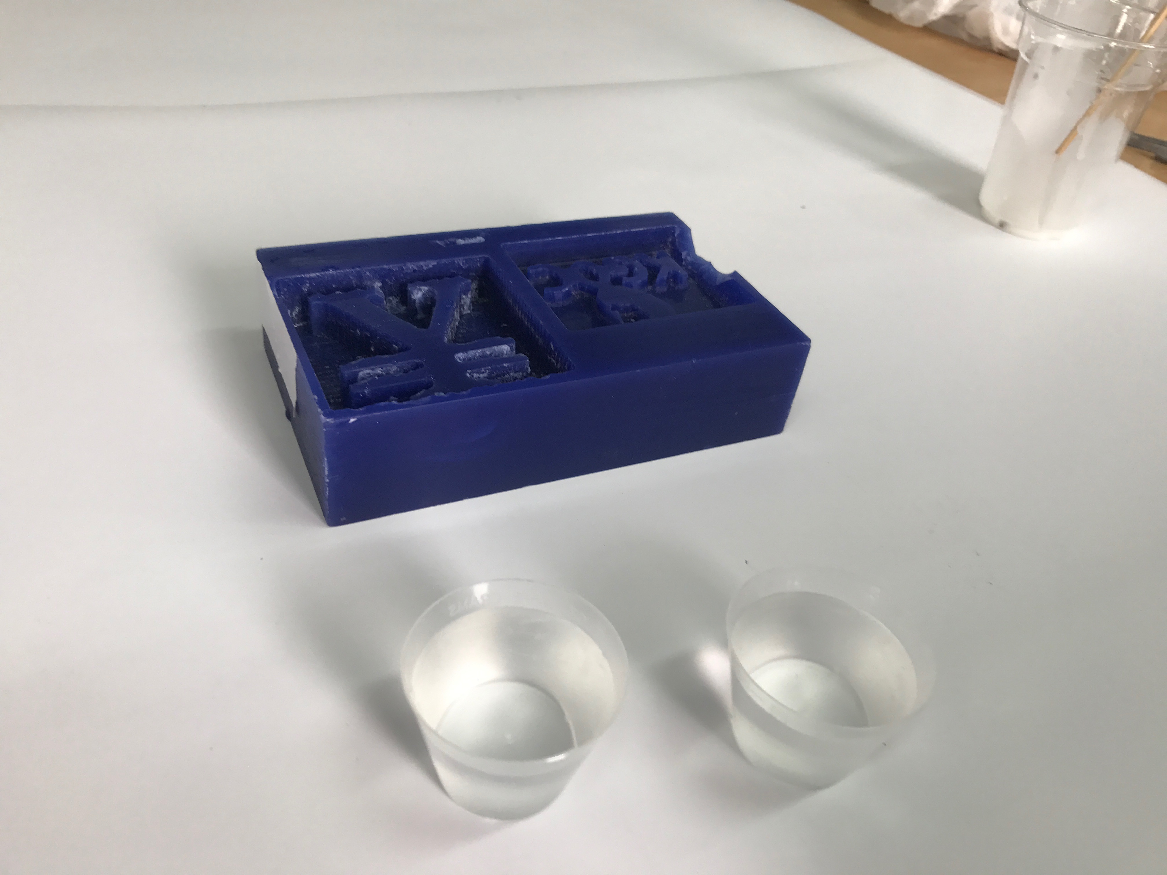
After measuring the quantity that I need. I mix the 2 solvent together for 6 minute. And then I add the mix that I got in the milled wax. It is very important to avoid having bubbles in the mold, and for that I avoid shaking and i kept some distance while adding the mixture into the mold.
pic missing
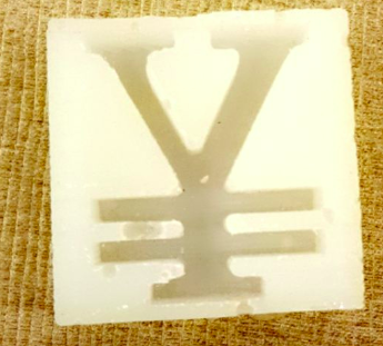
After adding the mixture I waited for 24 hours so it became harder. And this is the result.
Casting:
For the casting step I used Amazing Casting Resins, A and B. First I again measured the quantity and divided it for 50% for each cup.
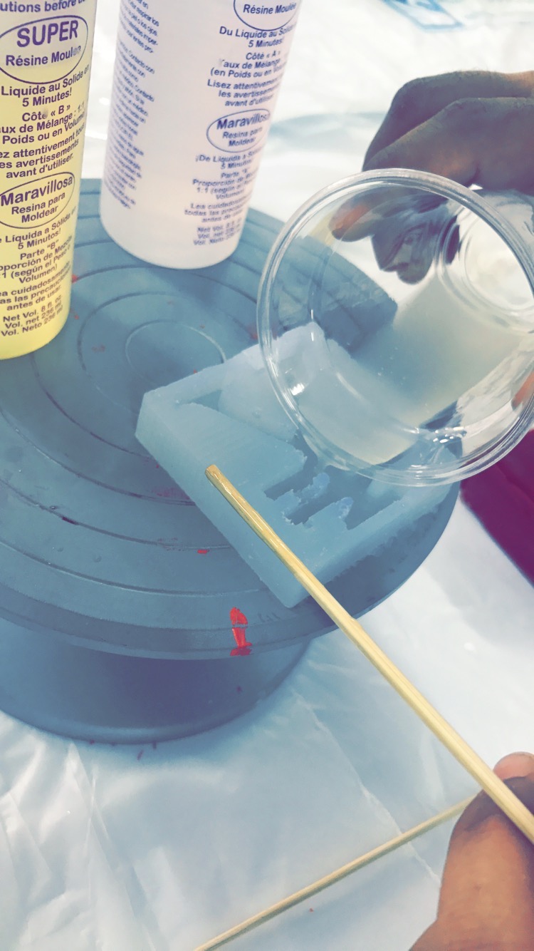
Then I mixed them very will for 30 second as this type of resins dry in short time. 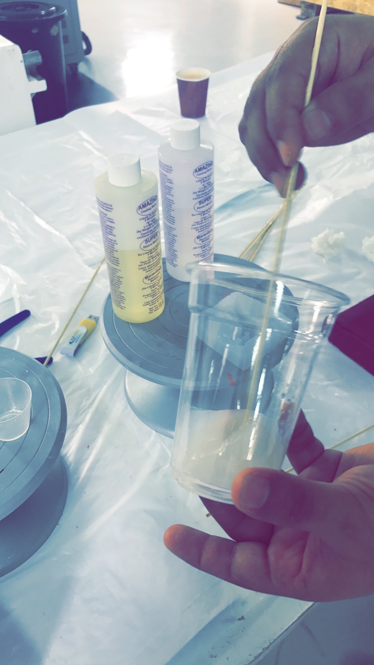 Finally I added the mixture in the silicon mold and waited for 30 minute for the mixture to dry.
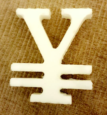
And this is the result.
 Design File
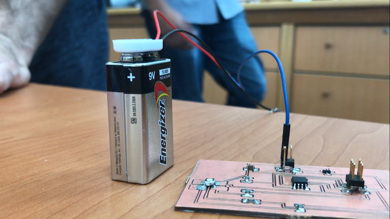
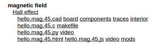
Magnetic Field Board
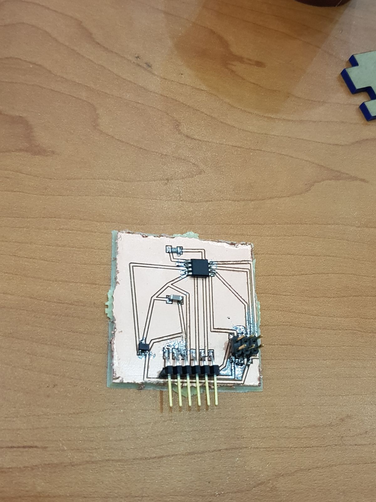
For this week. We should choose from the list in the Fablab archive for the week 13. Where I choose to make the magnetic filed sensor board to discover how these thing work. Where this board is going to give readings for any magnetic filed around.
 Magnetic Field Board
How Does a Magnetic Sensor Work?
Magnetic sensors detect changes and disturbances in a magnetic field like flux, strength and direction. Other types of detection sensors work with characteristics like temperature, pressure, light. From established knowledge about the existing magnetic field and the data collected from sensors regarding changes and alterations, many things can be known. Rotation, angles, direction, presence and electrical current can all be monitored. Magnetic sensors are divided into two groups, those that measure the complete magnetic field and those that measure vector components of the field. The vector components are the individual points of the magnetic field. The techniques used to create these sensors involve various combinations of physics and electronics.
By Alex Burke; Updated April 24, 2017
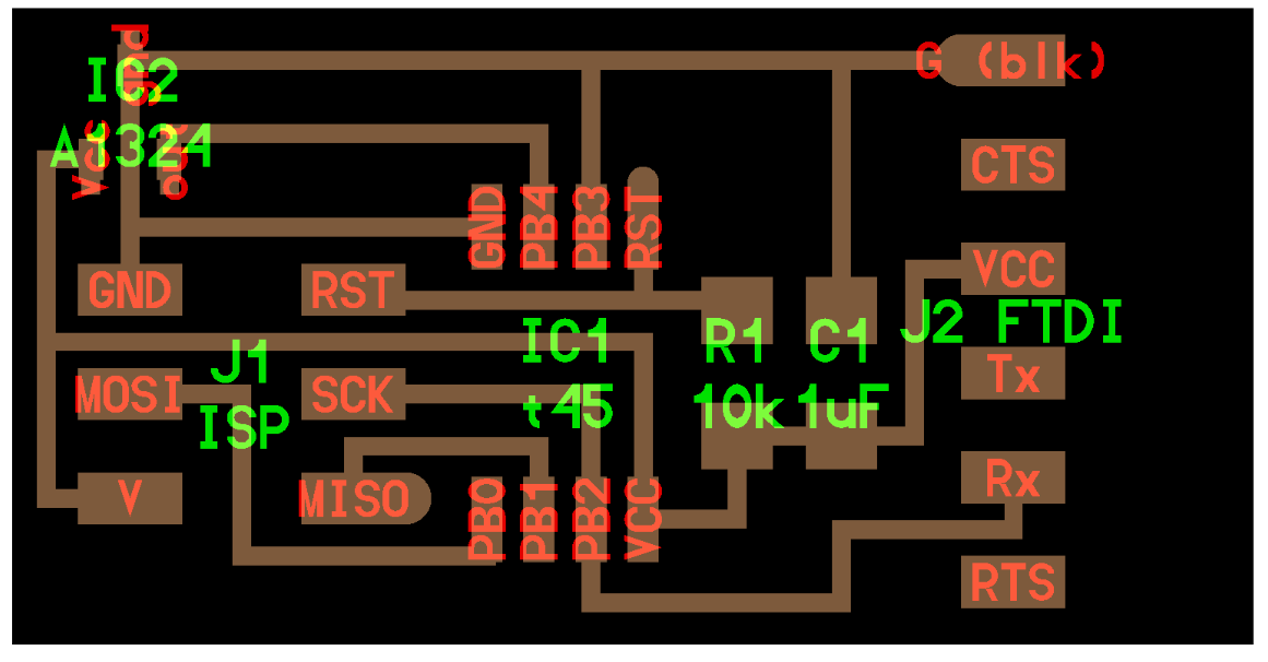
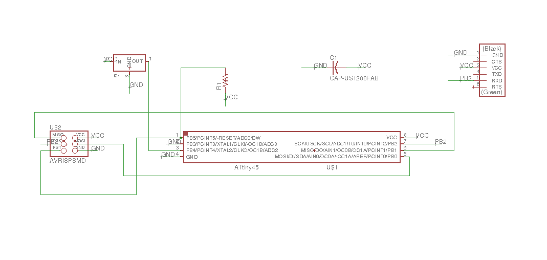
Board design
I start making the board circuit with eagle cad, and for the components I used in the board are Attiny45, resistor, campastor, AVRISPSMD, FTDI and regulator.
Schematic
Board rooting
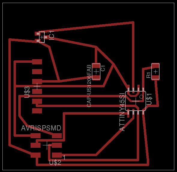
Final Board
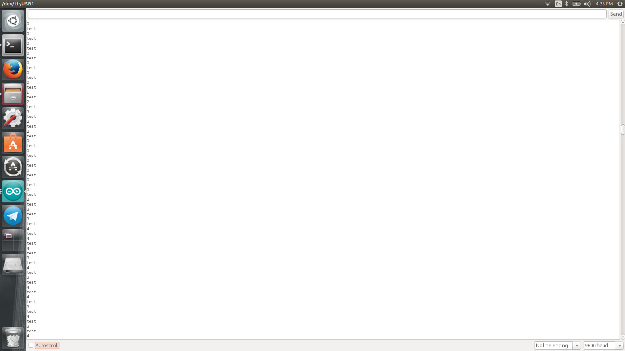
Testing
Then I test the board to see if it is working or not. For testing I connect my board to the laptop → open Arduino serial monetar program → check if the connection established → I rounded a magnet to the magnetic field sensor and then observe the reading. If there is a magnetic field the reading will show numbers and if there is not the result will be 0.
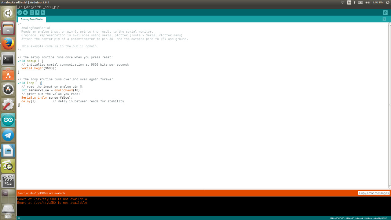
Programing
/*
AnalogReadSerial
Reads an analog input on pin 0, prints the result to the serial monitor.
Graphical representation is available using serial plotter (Tools > Serial Plotter menu)
Attach the center pin of a potentiometer to pin A0, and the outside pins to +5V and ground.
This example code is in the public domain.
*/
// the setup routine runs once when you press reset:
void setup() {
// initialize serial communication at 9600 bits per second:
Serial.begin(9600);
}
// the loop routine runs over and over again forever:
void loop() {
// read the input on analog pin 0:
int sensorValue = analogRead(A0);
// print out the value you read:
Serial.println(sensorValue);
delay(1); // delay in between reads for stability
}
Board Sch File Board Brd File
Composite
Assignment:
Design and make a 3D mould, and produce a fiber composite part in it.
Composite Material
A Composite material (also called a composition material or shortened to composite,which is the common name) is a material made from two or more constituent materials with significantly different physical or chemical properties that, when combined, produce a material with characteristics different from the individual components. The individual components remain separate and distinct within the finished structure. The new material may be preferred for many reasons: common examples include materials which are stronger, lighter, or less expensive when compared to traditional materials.
Reference
My Work
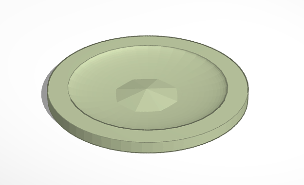
For this week am going to design and make 3D mould in order to produce a fibre composite part in it. For the 3D design I used TinkerCad I made a circle and A prominent triangle inside it. My design dimension is 15cm x 15cm and 15mm for the height. After I finish from the design I exported it as STL file.
After saving the file as .STL i used Artcam to convert it to .PLT file so the CNC machine can read it. Following are steps.
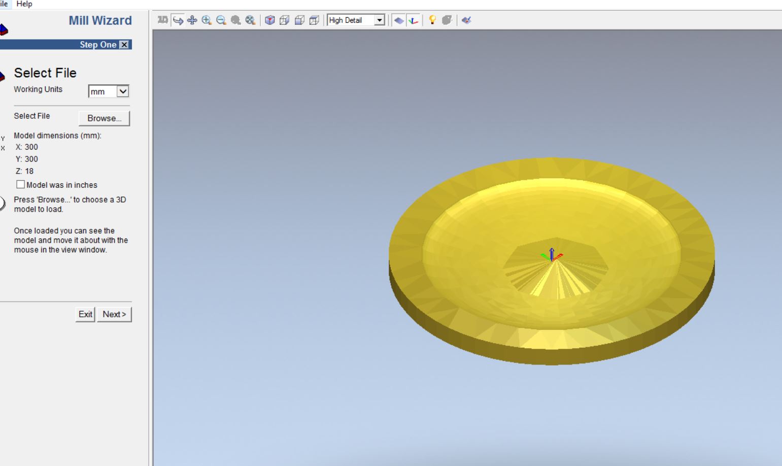
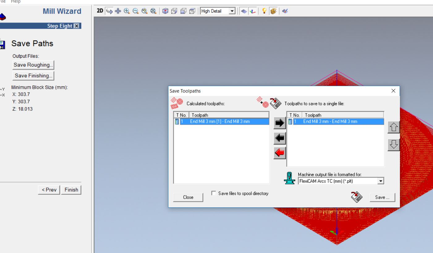
Milli wizard
File loading
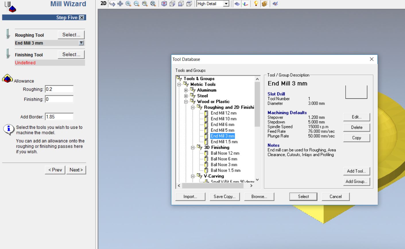
Tool Selection
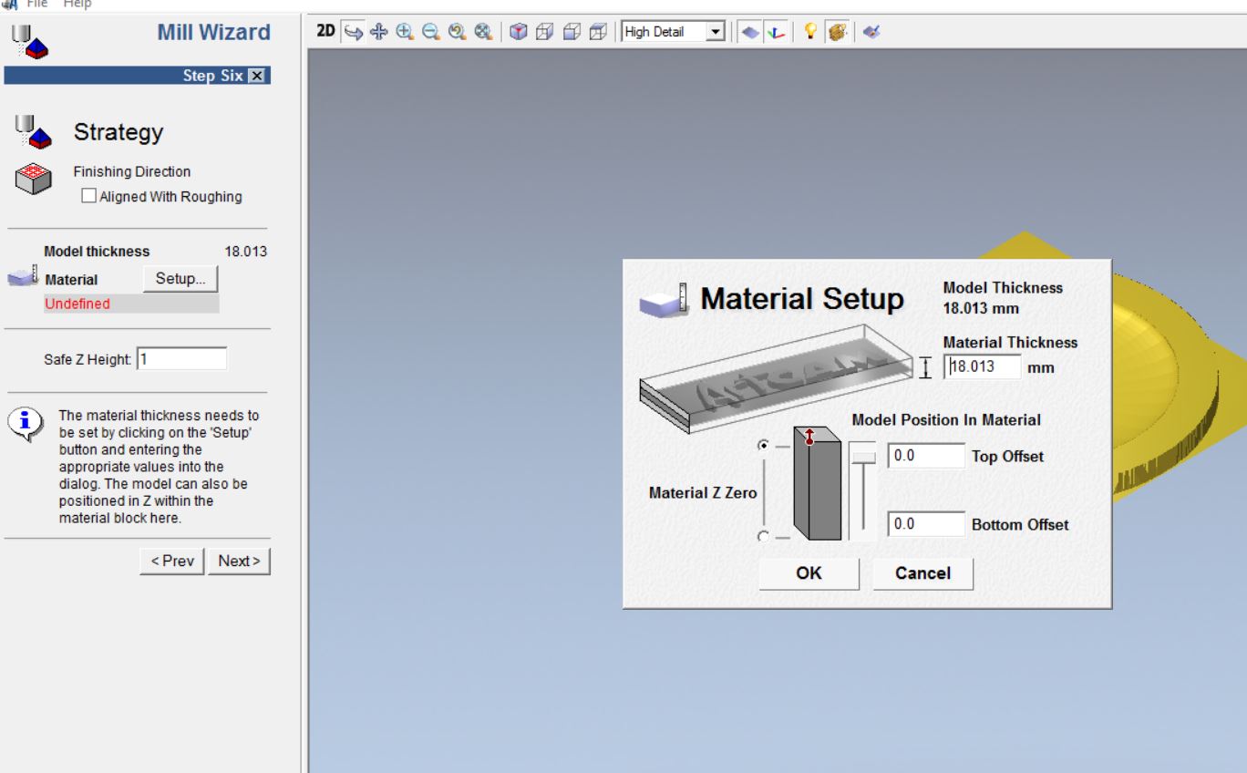
Material thickness and selection
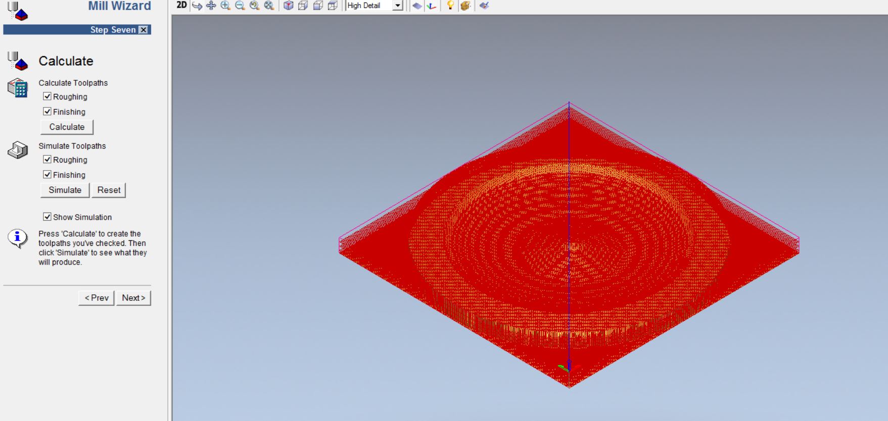
Simulating toolpaths
Toolpath saving
My design:
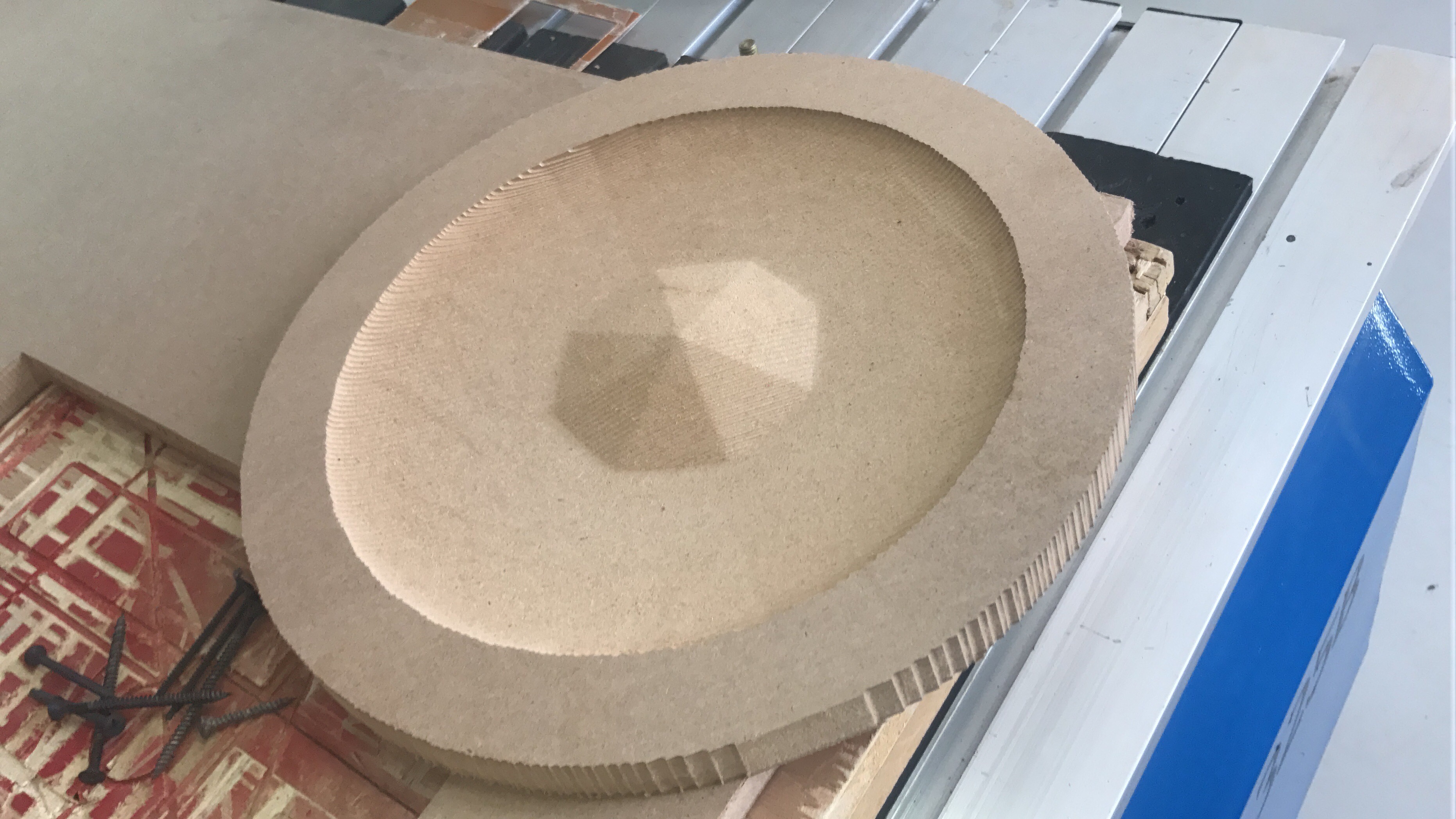
Milling :
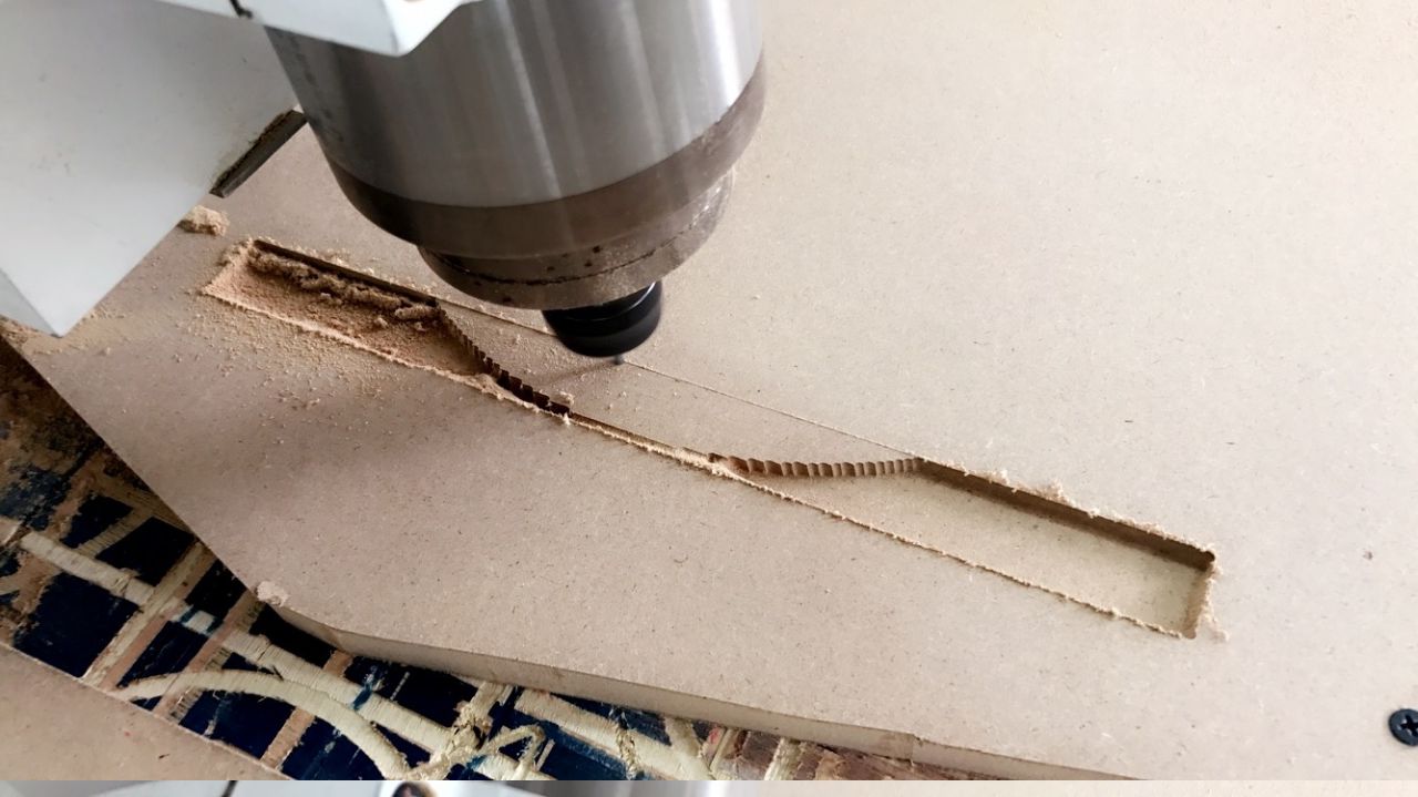
Before starting to work my i grap your attention for the following Precautions:
1) Avoid Contact with skin and eyes, wear gloves.
2) Do not mix the components of the crystal resin with the components of the glazing resin.
3) resins are not approved for food contact.
4) Do not exceed 150ml of crystal resin preparation per mix.
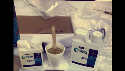
Composite :
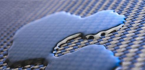
For the composite step am going to use crystal resin A & crystal resin hardener B, 2 cotton sheet, jute fiber and air vacuuming bag. Steps are as following.
First I covered my wooden shape with a plastic tape to take clear composite for the mould.
Second I used two resins A & B {Crystal Resin A & Crystal Resin Hardener B} in a ratio of 2:1 respectively and mixed them together for few minute.
Third I used cotton sheet to be the first layer and distributed the resin very will on the sheet.
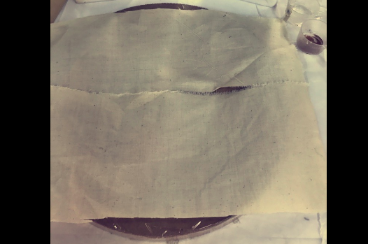
Fourth I used jute fiber for the second layer and also distributed the resin very will on the jute fiber.
Fifth again I used the cotton sheet as my third layer and distributed the resin will on it.
Sixth after am done from adding the layers on the wooed shape I covered it with plastic sheet roll and placed it in the air vacuuming bag and removed the air out of the bag.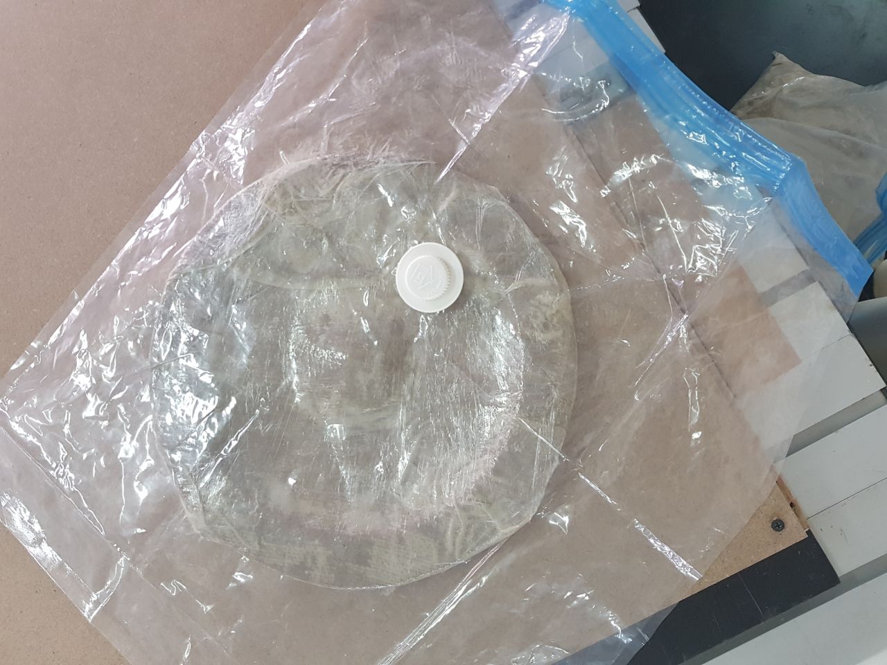
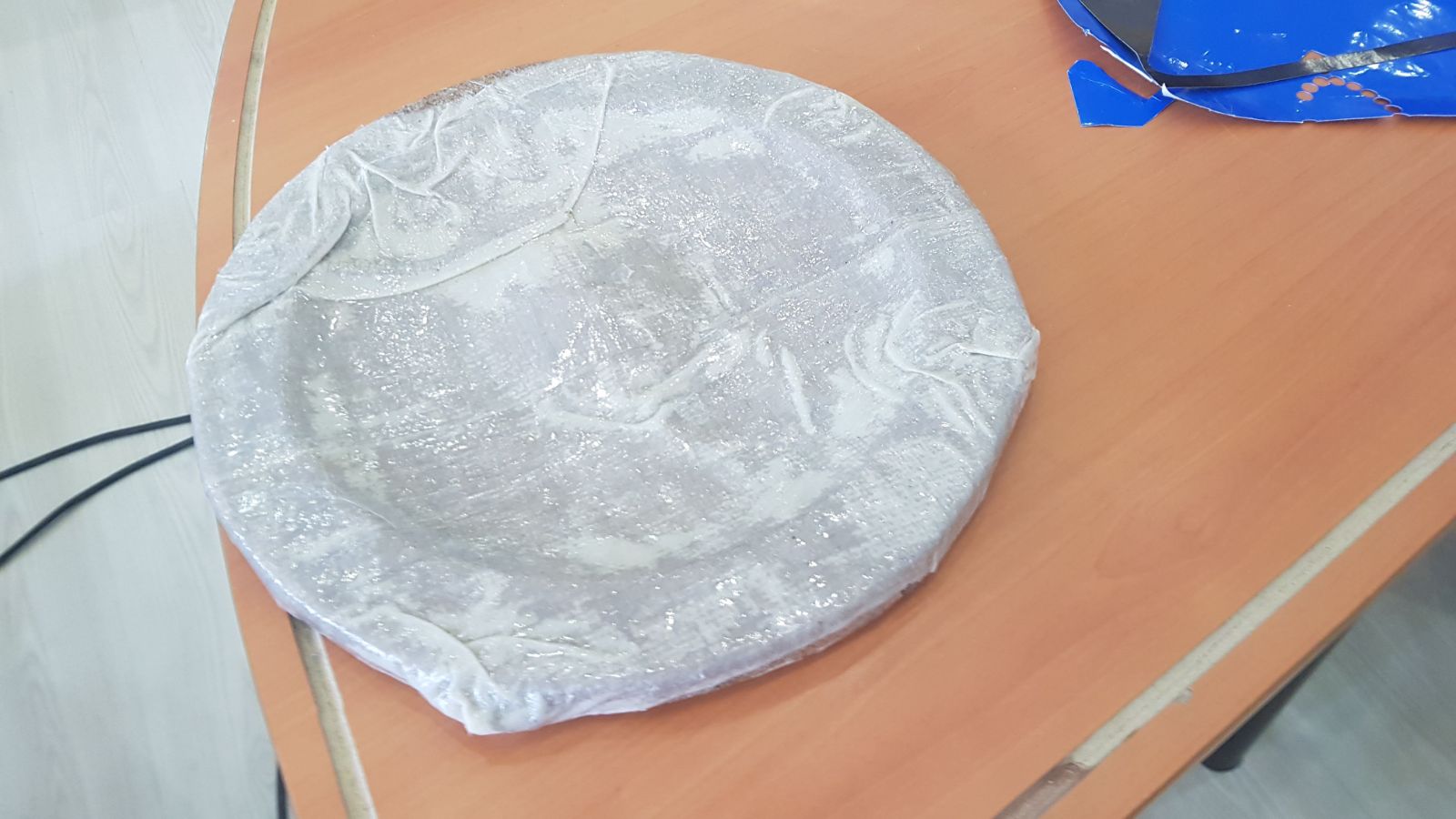
After leaving to for 24 hours to dry, Finally this is the result.
Networking and Communications
Assignment
Design and build a wired &/or wireless network connecting at least two processors
Introduction
Networking
The practice of interfacing two or more computing devices with each other for the purpose of sharing data. Computer networks are built with a combination of hardware and software.
Reference
Networking aspects and methods
1- Serial communication and transmission
Serial aspect of networking ensures that different programming devices can be automated while still installed in a complete system instead of plugging off the system before installing the program (Bhuyan et. al., 2014). In the following aspect and method, the system remains intact, and other programs can run despite the current reprogramming that is taking place in other logic devices (Bhuyan et. al., 2014). Several mutually incompatible in-system programming procedures are implemented for enhanced users within different contexts. Data is sent through a single byte on a parallel channel to reduce the discord that may arise during programming.
Reference
2- Serial Peripheral Interface (SPI)
It refers to an interface bus that is used to transfer data between a computer's microcontrollers and the small superficial network devices such as the sensors and storage cards (Bhuyan et. al., 2014) Data transfer is often carried out over short distances to enable effective communication. The SPI utilizes a two-way mode of communication with a single controller coordinating the activities of the peripherals. The SPI has a higher output compared to other devices since it has a straightforward and understandable interface as transceivers are not needed (Bhuyan et. al., 2014).
Reference
3- Inter-Integrated Circuit (I2C)
It is a serial computer bus that is used for affixing the low-speed peripheral ICs to computer processors and mini-processors over short distances. The I2C can also be synchronous in the sense that the amount of information being transmitted can be matched between the central computer and the microcomputers (Bhuyan et. al., 2014). The I2C lack the select slave lines for data transmission compared to the SPI. Since data transfer involves the clock system, it is possible to ensure that both data is coordinated to reduce any impact of an overwhelmed computer system.
Reference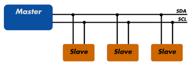
My Work
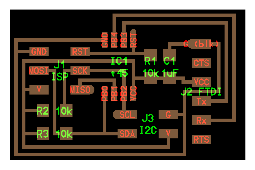
For this week am going to Design and build a wired serial network and am going to connect a the master board (redesigned hello.bridge) and two slave board (hello.node boards).
Master board
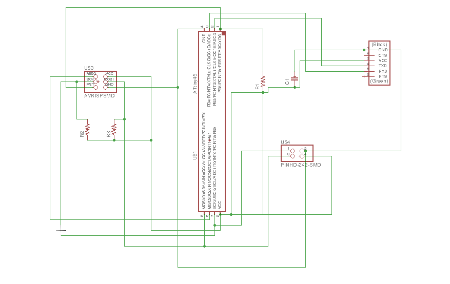
First I designed my master board and done from the rooting. Following are the Schematic and Rooting (Steps mentioned in earlier reports)
Hello.bridge board
Master board Schematic
Master board Rooting
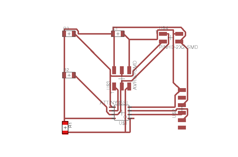
Soldering Master Board
Slave boards
For the slave boards I used LED for each one of the with deffrint color (RED & Blue). Following are the Schematic and rooting.
Hello.node boards
Slave board Schematic
Slave board Rooting
Soldering Slave Board
Work done and know programing start.
Programming:
Master Board Code :
#include <TinyWireM.h>
void setup()
{
TinyWireM.begin(); // join i2c bus (address optional for master)
}
byte x = 0;
byte x1 = 0;
void loop() {
TinyWireM.beginTransmission(0x1);
TinyWireM.write(++x % 2);
TinyWireM.endTransmission();
delay(4000);
TinyWireM.beginTransmission(0x2);
TinyWireM.write(++x1 % 2);
TinyWireM.endTransmission();
delay(4000);
}
Slave1 Board Code :
#define output(directions, pin) (directions |= (1 << pin)) // set port direction for output
#define input(directions, pin) (directions &= (~(1 << pin))) // set port direction for input
#define set(port, pin) (port |= (1 << pin)) // set port pin
#define clear(port, pin) (port &= (~(1 << pin))) // clear port pin
#define LED_PIN PB3
#define I2C_SLAVE_ADDRESS 0x1 // Address of the slave 1
#include<TinyWireS.h>
void setup()
{
output(DDRB, LED_PIN);
clear(PORTB, LED_PIN);
TinyWireS.begin(I2C_SLAVE_ADDRESS); // join i2c network
}
void loop()
{
byte recd = 1;
if(TinyWireS.available()) {
recd = TinyWireS.receive();
if(recd == 1) {
clear(PORTB, LED_PIN);
} else {
set(PORTB, LED_PIN);
}
}
}
Slave2 Board Code :
#define output(directions, pin) (directions |= (1 << pin)) // set port direction for output
#define input(directions, pin) (directions &= (~(1 << pin))) // set port direction for input
#define set(port, pin) (port |= (1 << pin)) // set port pin
#define clear(port, pin) (port &= (~(1 << pin))) // clear port pin
#define LED_PIN PB3
#define I2C_SLAVE_ADDRESS 0x2 // Address of the slave 2
#include<TinyWireS.h>
void setup()
{
output(DDRB, LED_PIN);
clear(PORTB, LED_PIN);
TinyWireS.begin(I2C_SLAVE_ADDRESS); // join i2c network
}
void loop()
{
byte recd = 1;
if(TinyWireS.available()) {
recd = TinyWireS.receive();
if(recd == 1) {
clear(PORTB, LED_PIN);
} else {
set(PORTB, LED_PIN);
}
}
Master board Sch File Master board Brd File
Slave board Sch File Slave board Brd File
Interface and Application Programming
- Assignment :
Write an application that interfaces with an input and/or output device that you made, comparing as many tool options as possible.
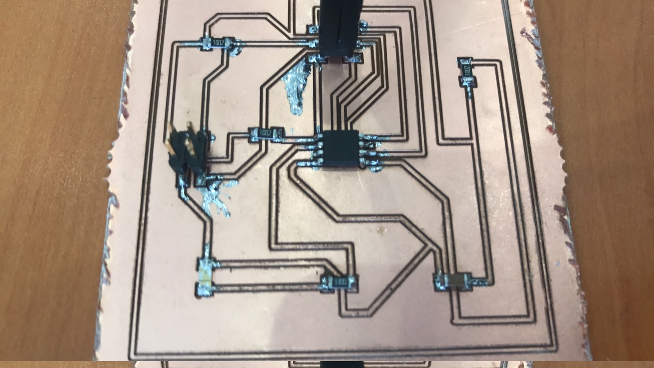
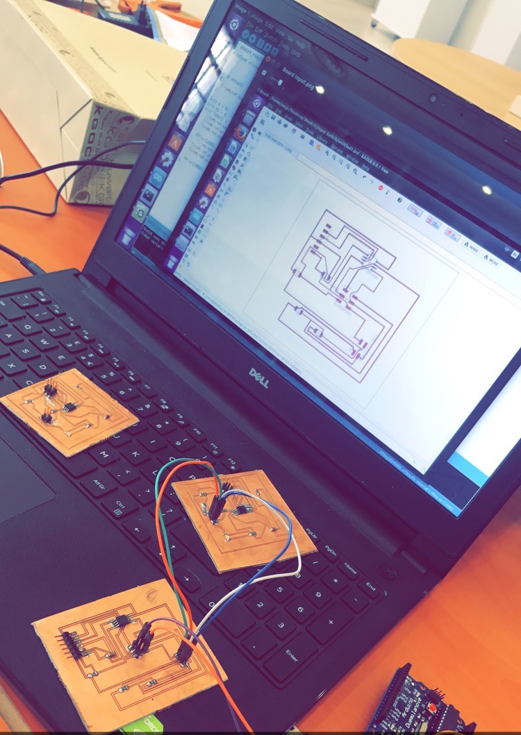
- My Work
For this week am going to write an application that interfaces with an output device that I made. Where am going to to use LED light and control it via application using bluetooth.
- Bluetooth

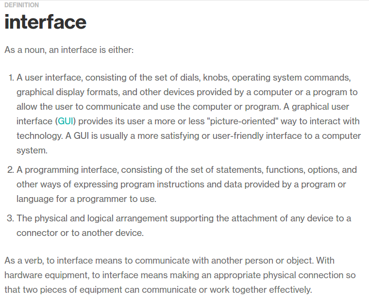
- Interface
- Bluetooth module (HC-06)
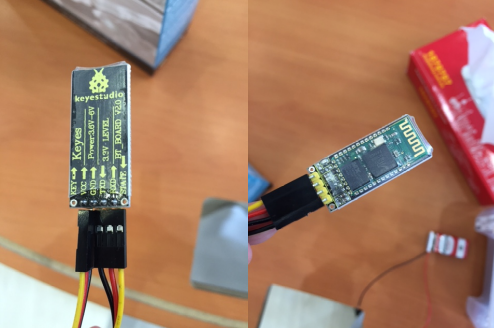
- Bluetooth protocal: Bluetooth Specification v2.0+EDR
- Frequency: 2.4GHz ISM band
- Power supply: +3.3VDC 50mA
- Modulation: GFSK(Gaussian Frequency Shift Keying)
- Emission power: ≤4dBm, Class 2
- Profiles: Bluetooth serial port
- Speed: Asynchronous: 2.1Mbps(Max) / 160 kbps, Synchronous: 1Mbps/1Mbps
- Security: Authentication and encryption
- Working temperature: -20 ~ +75 Centigrade
- Sensitivity: ≤-84dBm at 0.1% BER
- Dimension: 26.9mm x 13mm x 2.2 mm
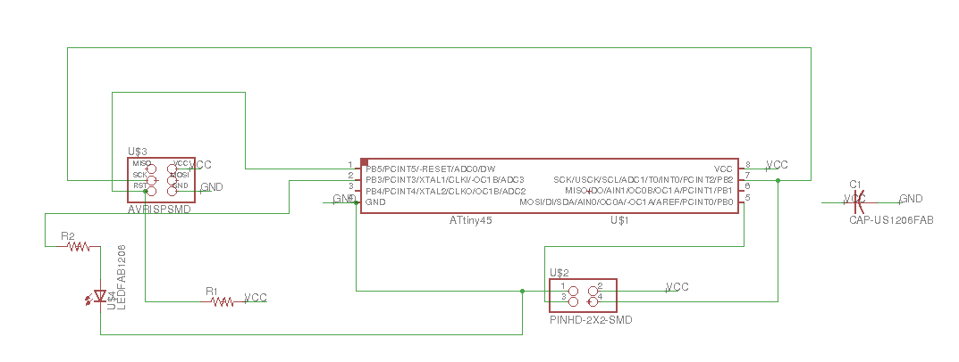
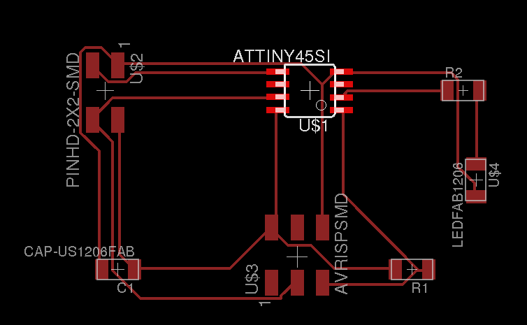
- Schematic design & Rooting
- Program Code
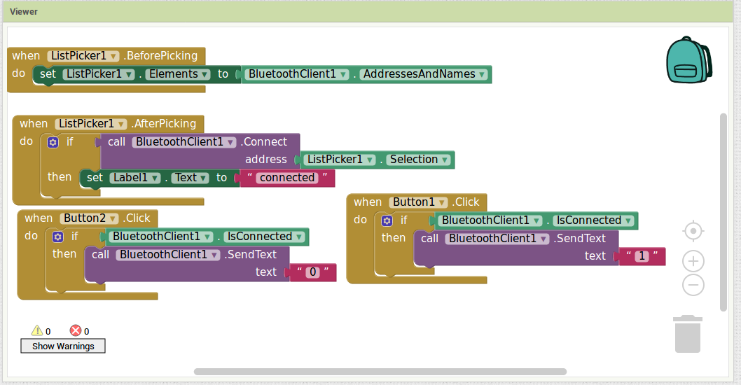
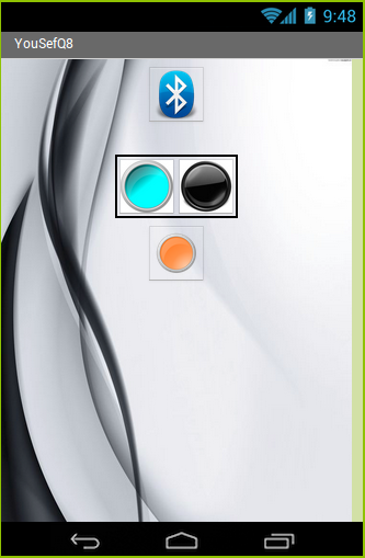
- Writing the Application
For writing the application I used MIT App inventor2 . Which is very easy and great web for writing application. For me I do not have any background in writing applications but using MIT web I did it right from the first time.
 Useful tutorial
- Programming :
This is the code that I used to program the micro controller in the board.
#include <SoftwareSerial.h>
SoftwareSerial mySerial(0, 2); // RX, TX
void setup() {
mySerial.begin(9600);
pinMode(4,OUTPUT);
digitalWrite(4,LOW);
}
void loop() { // run over and over
if (mySerial.available()) {
char a=mySerial.read();
if(a=='1'){
digitalWrite(4,HIGH);
}else if(a=='0'){
digitalWrite(4,LOW);
}
}
}
Board Brd File
Board Sch File
App inventor File
What will it do?
I decide to make an alarm that force me to wakeup, and that is by the design that am making, where after I set the alarm to start ringing at 7AM, at the time the alarm going to throw a ball and start ringing, so to which the alarm off I need to find the ball and put it back inside the alarm. And after I leave my bed I never go back, so the mission is accomplished and am up.
Who has done what beforehand?
I found a lot of good and strange alarm ideas. For example, the flying alarm when it start ringing the alarm fly vertically and fall beside you where you have to put it back to switch it off and go back to sleep. But for my alarm project, you have to first leave the bed second switch on the room lights third search for the ball fourth take the ball back inside the alarm.
What materials and components will be required?
- Servo Motor
- Bluetooth to communicate with the alarm
- Sensor to detect the ball and switch off the alarm
- Attiny84
- Copper plate
- Acrylic
- Wood (CNC) for the box
Where will they come from?
All of them are available in our lab inventory
How much will it cost?
My Project is almost 0 cost as I found all materials and components in our lab inventory
What parts and systems will be made?
- CNC cut for the Boxing (Wood).
- 3D Printing for the ball & ball path.
- Electronic Boards
- Acrylic for decoration
What processes will be used?
- CNC for the boxing
- Laser Cutting for Acrylic decoration
- 3D printer for the ball & ball path
- Cirquid for the board
What tasks need to be completed?
The decoration of my alarm as a final touch.
What questions need to be answered?
- How accurate will the camera/image process would be ?
What is the schedule?
- Structure wooden1 Days (07/06/2017)
-Electronics boards2 Days(08/06/2017)
-Assembly & Programming 2 Days(10/06/2017)
-Error fixes and Improvements1Day(13/06/2017)
How will it be evaluated?
For the final project I hope it will be well evaluated, because the idea comes from a need. And it is well implemented. I choose this project as am in real need for it and I really implement what I learned through the last period of 6 month.
Invention, intellectual property, and income
Assignment
This week assignment is about invention, intellectual property, and income. The goal of this assignment is to develop a plan for dissemination of our final project.
license
"Licensing means renting or leasing of an intangible asset. It is a process of creating and managing contracts between the owner of a brand and a company or individual who wants to use the brand in association with a product, for an agreed period of time, within an agreed territory."
Reference
Intellectual property
"Intellectual property refers to creations of the mind: inventions; literary and artistic works; and symbols, names and images used in commerce."
Reference
License Types
MIT license
MIT license refers to a set of open source software that was designed and originated from Massachusetts Institute of Technology (Henkel et. al., 2014). The software has a limited restriction regarding its use and allows reuse as long as the final product highlights the software's original terms of service. However, the designer of the software is not liable for any consequences regarding the continued use of the software, and the user can only accredit the owner by indicating their name on a particular section of the software. As such, the designer does not guarantee quality regarding the quality of the software provided for use by the second and subsequent parties (Henkel et. al., 2014)
Creative Common (CC license)
In the CC license, the designer offers their users an opportunity to use and redistribute the software to other individuals while they take into consideration the terms and conditions outlined in the license. Furthermore, the creative common type of license protects the users of the software from issues of copyright infringement while redistributing the software. The user of the software is required to accord the designer an appropriate credit by highlighting the license notice, copyright notice and the names of the designers together with any other attribution parties (Henkel et. al., 2014). Additionally, the user can provide a hyperlink to show attribute for their commercial and non-commercial usage.
CC License Link
GNU General Public License (GPL)
The type of license, which was published in 2007, provides the end user with an opportunity to run, offer others, study and make changes to the software (Colombo et. al., 2014). Further, the General Public License (GPL) is a copyleft license meaning that the subsequent works arising from its modification can only be redistributed with similar initial terms as for the original works. The software also provides the end users with the rights articulated in the free software definition. It highlights that the designer has no legal authority to impose restriction regarding the usage of the software as long as the distributor or user abides by the terms and conditions of operating the software (Colombo et. al., 2014).
BSD License
It is a type of single license intended for the computer software initially developed at the California University of Berkeley. The license was first utilized in 1980 for the Berkeley Source Distribution also referred to as BSD UNIX (Henkel et. al., 2014). The license required that if users intended to modify or redistribute the software in any form, they had to ensure that they maintained the original copyright notice, a list of the condition of liability and another list of reasonable restrictions. In case an individual did not write the software, they had no responsibility to claim any form of compensation accruing from the benefits of the software despite any modifications made.
Apache License
The Apache license type of license is an open source software meaning that individuals can use, distribute, run and modify any of the Apache licensed products while following the specific conditions outlined by the Apache foundation. It was released by the Apache Software Foundation (ASF). The terms state that users have the right to utilize both the copyrights and patents for the software in contrast to other software that only grants the right to copyright. The Apache license also allows a user to add any modification without accrediting the source license and thus, individuals can add their specific terms in their new models.
Apache License
Mozilla Public License Version 2.0
The Mozilla Public license is a class of licenses that endeavors to reduce the copyleft restrictions on the coding that it covers. In the earlier Mozilla versions, so many adaptation restrictions reduced the compatibility of the Mozilla software and other internet files (Henkel et. al., 2014). The new version has also allowed the Apache License to be compatible and easily be incorporated into the other Mozilla releases. The compatibility feature has ensured that users outside the United States are accorded less enforcement and restrictive practices (Henkel et. al., 2014). As such, the license has been made shorter and easily understandable by all its users.
Mozilla public license version 2.0
Project license
I will use Creative Common with the following:
- Attribution (BY) - Non Commercial (NC).
- No Derivative Works (ND).
I choose this kind of license as it has benefits for the owner and forbids the commercial use for the product.
Project Development
Assignment:
●Complete your final project. Track and document your progress.
My Invention:
My project is an alarm and what is special in that alarm is, when you set the alarm to start in a certain time a ball will fall dawn from the alarm and the buzzer will start making sound and it want stop until you search for the ball and put it back inside the alarm.
What is the deadline? How much time do I have left?
The deadline for my final project presentation is 16-June 2017.And I have 1 day to finish my project and complete my project presentation slide.
What tasks have been completed, and what tasks remain?
Completed:
I used CNC Machine it cutting my wooden box for the alarm.
Laser cutting to cut acrylic and attach it to the box for decoration.
3D printer to print the ball that going to be inside the alarm
my board schematic design in eaglecad, printed it on the copper board and soldering the component.
Programing my board.
Testing the electronic parts. Bluetooth, servo motor, sensor and the buzzer. And every thing worked fine
Remain:
Assembling the alarm
●How will I complete the remaining tasks in time?
- Structure wooden 1 Days (07/06/2017)
- Electronics boards 2 Days (08/06/2017)
- Assembly & Programming 2 Days (10/06/2017)
- Error fixes and Improvements 1 Day (13/06/2017)
What has worked ?
The servo motor worked fine where when the alarm start the servo motor move and let the ball to fall out of the alarm box, also the buzzer worked fine and after the ball fall dawn it start peeping. The sensor stops the alarm when I take the ball back inside its bath it the alarm box. Finally the Bluetooth help me in setting up the alarm and it is also working fime.
What hasn't ?
while programing my board I the attiny44 did not have enough space for the program so I removed the attiny44 and replaced it with attiny84 after that I downloaded the program and tested the electronics and all goes will.
What questions still need to be resolved?
what am going to use to hang the alarm ?
What have you learned?
I learned how to make electronic communicate to make them do what I want.