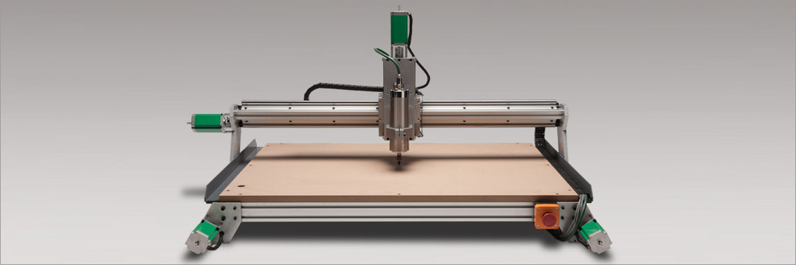
CNC (Computer Numerical Control router)
In this week, We will create BIGGER stuff. By using the CNC, we can design a shape or several parts separated with larger scaling. The machine will cut the parts accurately ordered by the computer to follow the routes of the design automatically and without repeating the procedure more often. We will see how this works and it will be very easy.
History of CNC
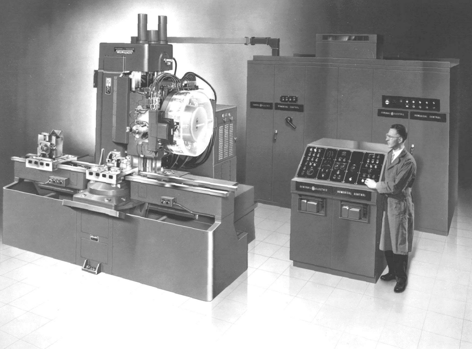
This machine came out after World War II. The companies that produces aircrafts want to create more parts which have a feature of accuracy and complexity.
For more details:-
About CNC Back into the years, there is a machine called NC “Numerical Control”. This machine cuts the parts using numbers, letters and symbols. This will be done manually without seeing the design how it going to be look like after finishing the cutting. People were having difficulties operating this machine due to lack of technology.
For more details:-
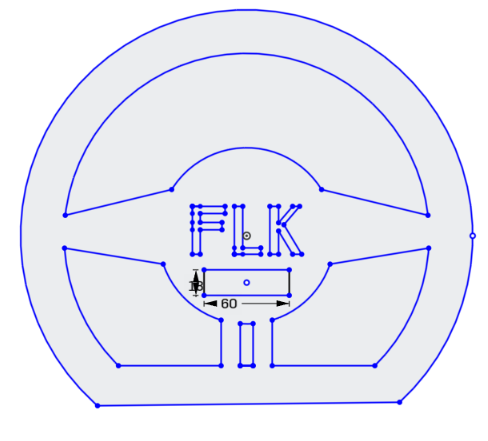
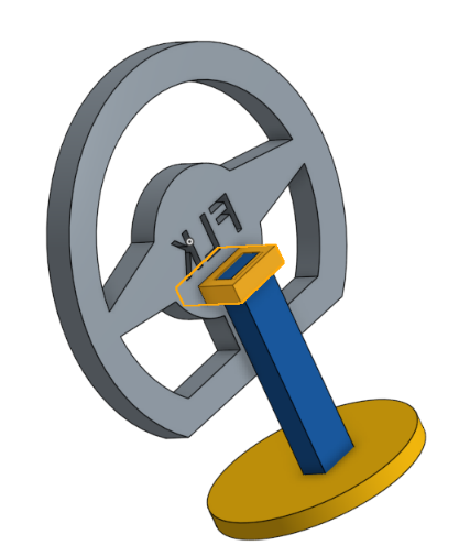
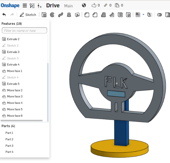
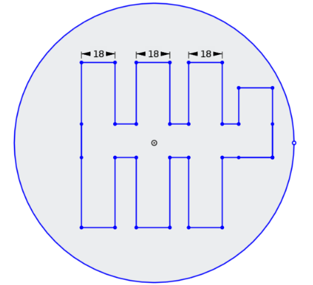
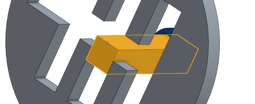
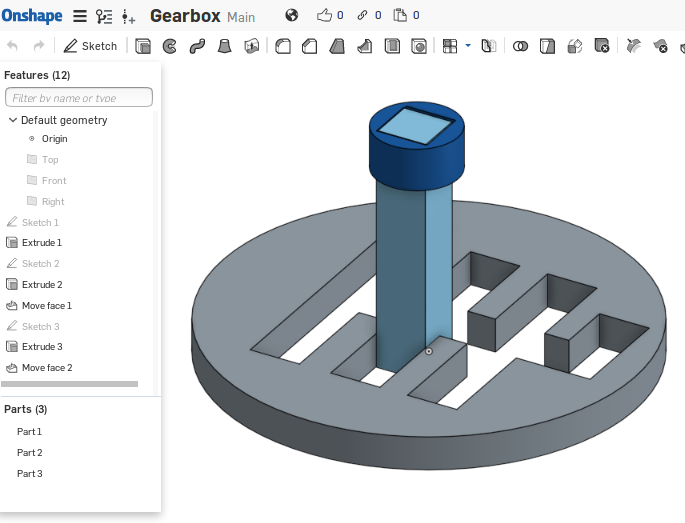
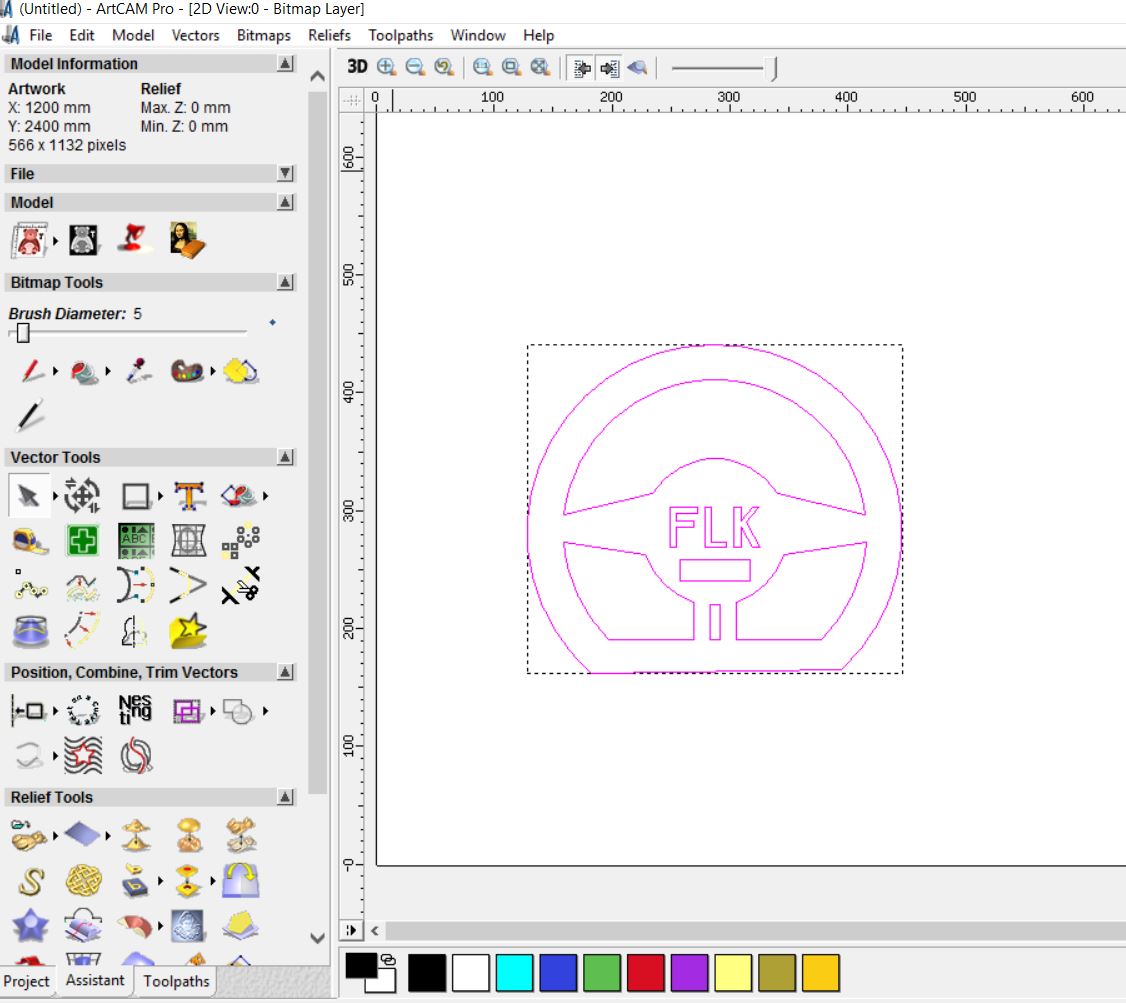
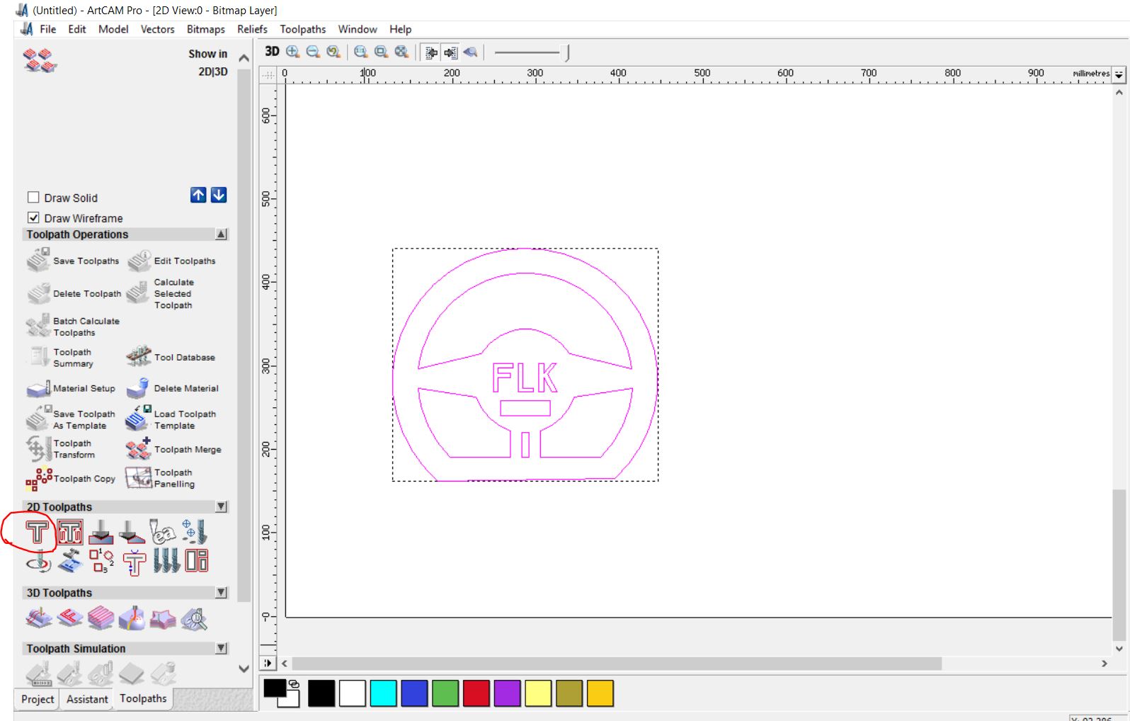
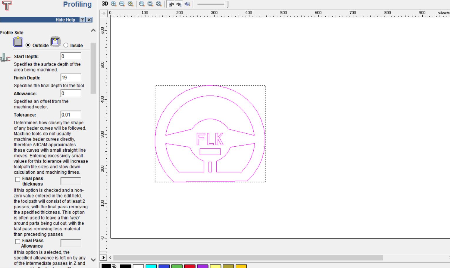
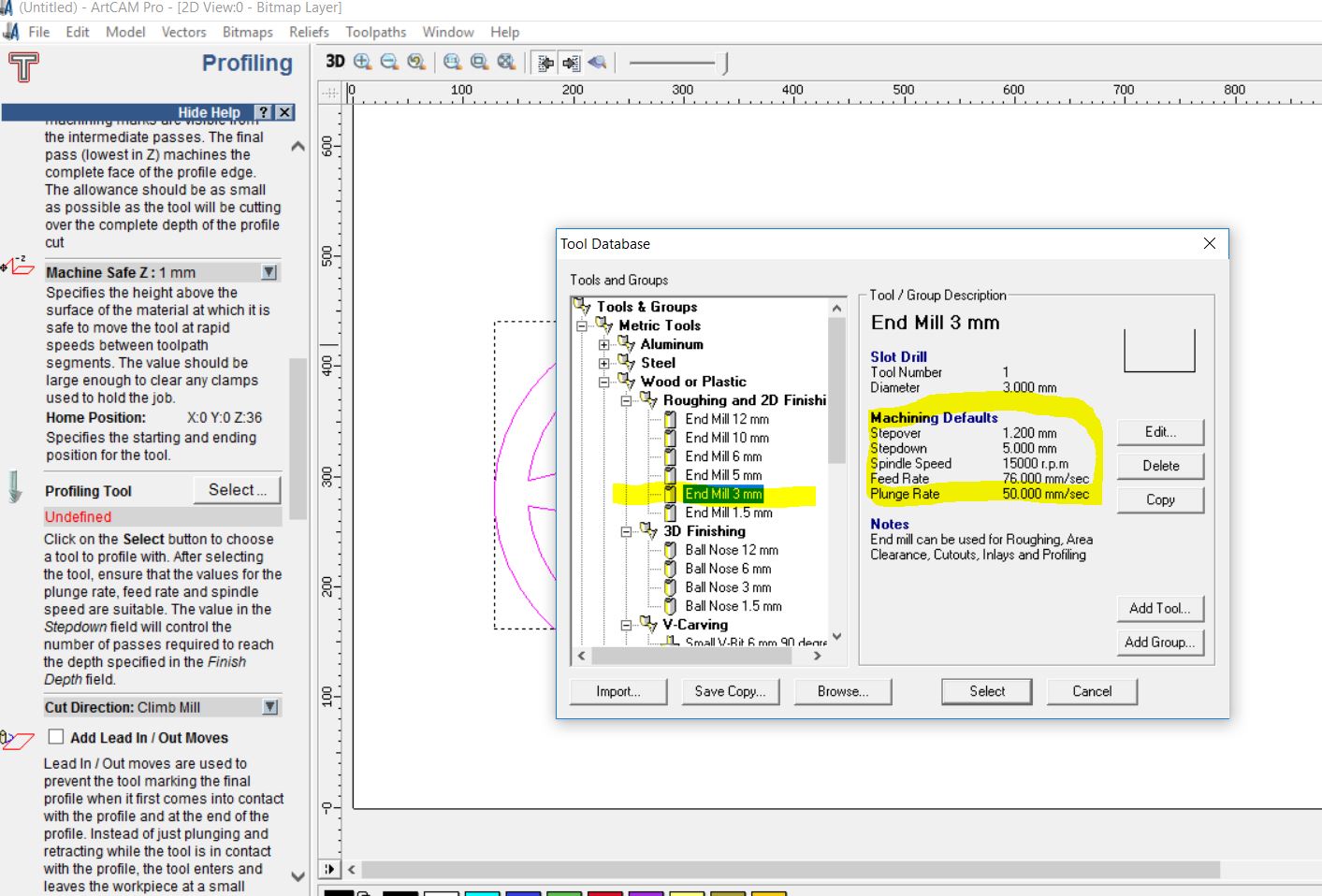
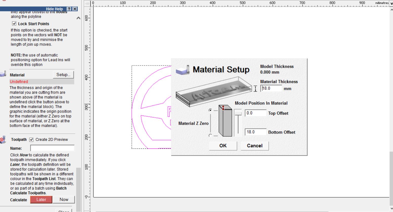
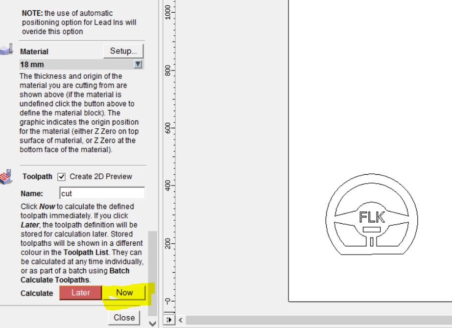
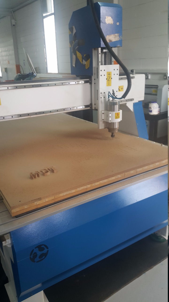
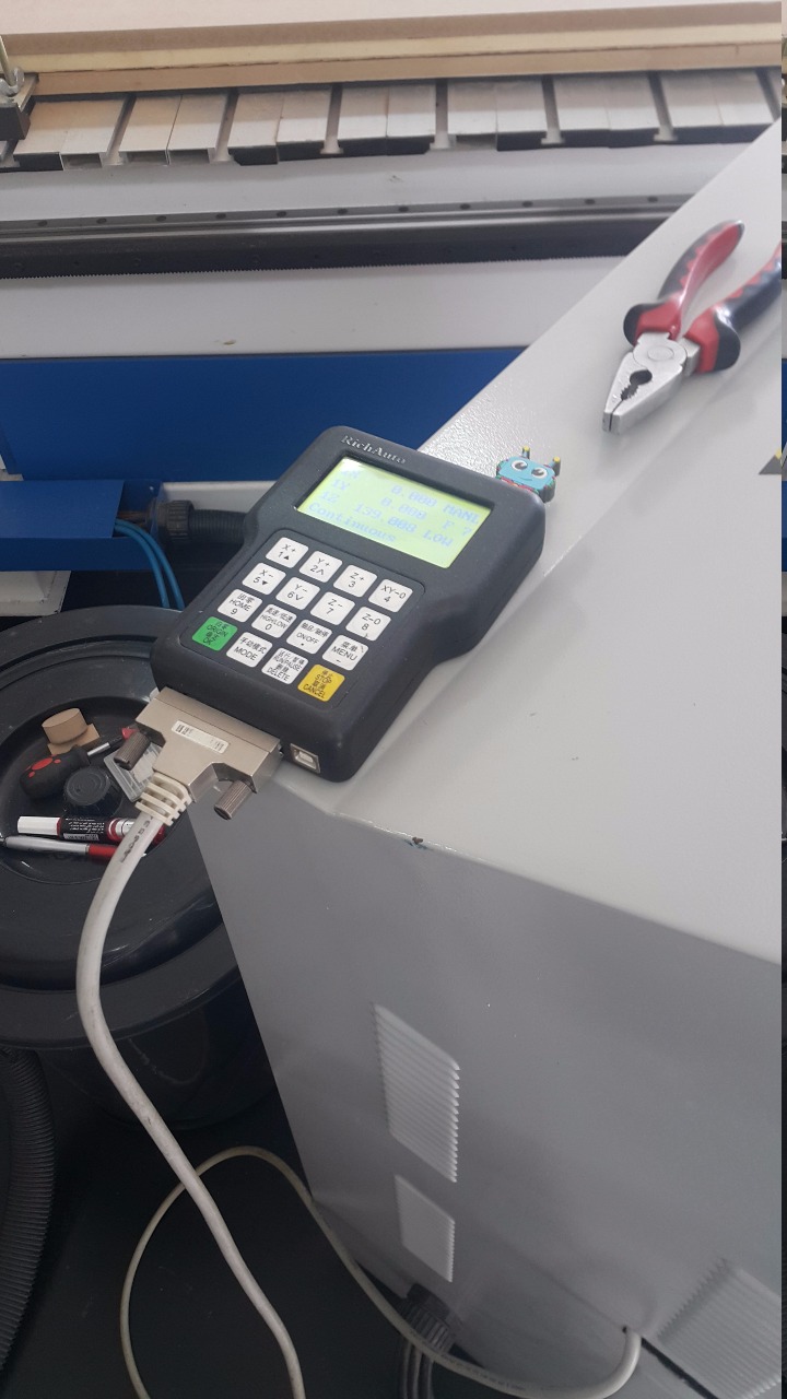
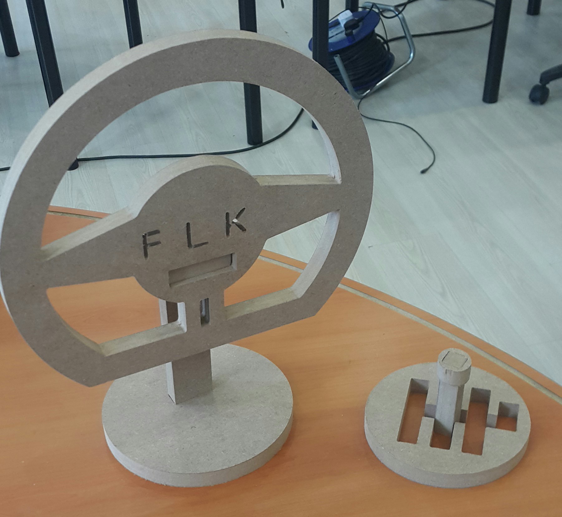
The Design Using Onshape, the design is going to be a steering wheel and a gearbox as in race cars. It will not be difficult to create them both, but it is a matter how it can be made. I tried to be very simple and straightforward. First of all, the steering wheel will be made. Starting with the face of the wheel, I chose of make a sport’s car wheel as it is shown in the picture above. It is a circle with a straight surface at the bottom to give it a sporty look. Using lines and cutting tools to create the empty areas inside the wheel. In addition to the FLK, it is a name which stands for FabLabKuwait. The main thing of the wheel is the attaching hole between the wheel and the hanger behind it, which is the middle rectangle (18,60mm). The rectangle will be attached with the hanger with is highlighted in the above picture. This will make a connection between the wheel and the pole. Then, the pole will be plugged in the base part on the ground which is the circle yellow base. This is how it should look after attaching all the parts together. The wheel looks realistic and it will be just for show as something for fun inside garages or car showrooms. We will make the gearbox now. It is a simple design using a circle with lines inside it to create this look of the gear shifting routes. I focused on making the width of the holes to both designs to (18mm) because it is the width of the wood that will be cut. So I need to be careful otherwise the parts will not be attached together. Now, by making the gear leaver, we need to make only a rectangle with a width of (18mm) and the height does not matter a lot, depends on the person. The width is important to attach the gear leaver into the gearbox routes as it is shown in the picture. This is the final demonstration of the gearbox design. Just to give it more realistic touches, I put the gear hand holder on the top of the gear leaver using a circle and a square inside it of a width (18mm) to fit in it. Now we made the steering wheel and the gearbox. It is now to covert these files to enable the CNC to cut it using a software called ArtCam. The conversion using ArtCam To import the file, go to Vectors/Import... and then select the file to be imported. The file is now imported as you can see in the picture above. In order to create a path for the CNC to read, go to the 2D toolpaths section on the left and choose the "T" tool. You need to set the Finish Depth to the thikness size of the wood to be able to fully cut it. I have set the Finish Depth to 19. And also set the Tolerance to 0.01 to make the machine follows very close curves. Now, you have to specify the tool to be used to cut the wood. Go to Profiling Tool on left side and press the Select button. The tool database box will appear. I used the End Mil 3 mm, and the calculation of the speed has been set to 15000 rpm for the Spindle speed, 76.000 mm/sec for the feed rate and 50.000 mm/sec for the plunge rate. Now, to define the material depth, go to Material on the left and press the Setup button. The material thickness is 18 mm, so write down 18.0 mm on the material thickness box and the bottom offset box. To confirm all these specifications, go to the end of the left side section and write down the name of the toothpath and press Now button. This is the CNC i will be using to produce my shape which is the Wheel and the Gear box. Shortly will be shown as a final outcome. I put my USB which contains my file to be cut into the CNC controller shown in the above picture and select the file to start cutting. This will be my favorite design ever. Problem fixing I need to be careful when choosing the measurement numbers. I forgot to put the design with cm and chose mm. The CNC is big and did not cut becuase of the small size of the design. After that i thought of it, i need to make it in cm with the measurement that I have with my design. This time, it worked well and started to cut the shape.
CNC tutorial This is a very simple guide on how to use the CNC machine explained by Jeremy Schmidt:-
In 1949, the concept was developed by John Parsons. He thinks that he can make better aircraft skin parts than the old ones. He has opened the minds of MIT university to make more research about this subjects and the advantages of going into this road.
The people that were involved in making the research of this subjects are rof J.F. Reintjes, director of the lab, James O. McDonough, Richard W. Lawrie, A.K. Susskind, and H.P. Grossimon.
In 1950s They had started the assembly line of the CNC machine. At the beginning, the machine as a prototype, has not a perfect functioning. They still need to make more research about how to be more accurate and do more complex parts.
However, nowadays a new machine exists which is the CNC, a replacement of the NC by adding the C letter which is “Computer”. Now, there is a big difference between the two. The CNC now can control the machine using software design operated by programs providing visual shapes before cutting. It is more expensive and requires a lot of maintenance. On the other hand, professional people have the awareness of knowing which parts of this machine is essential and most important that can give them the main point of CNC.
There are many reason behind that. Some of the CNC parts are not needed for the cutting which are called additional features or tools come with it. But also, some people want to have a high category of cutting or we can say more luxurious than the base CNC. It depends on the person. But as for us Fablab students, we only want to cut the parts to finish the projects that we want to create at the end. In addition, learning more about the cutting procedures.
About CNC machine
.png)
Steering Wheel (Onshape)
Steering Wheel Part 1
Steering Wheel Part 2
Steering Wheel Part 3
Steering Wheel Part 4
Gear Box (Onshape)
Gear Box Part 1
Gear Box Part 2
Gear Box Part 3