About Electronics
In this week, I have created a board for the electronic side of the project. The requirements are Eagle Cad program for converting the board file into a real one. The other thing is a hardware device which is called Criquid, and this device is for converting the file into the board by printing the electric circuit on the copper board itself. On week six, we will use the EAGLE program to create the schematic design for the PCB we are making right now.
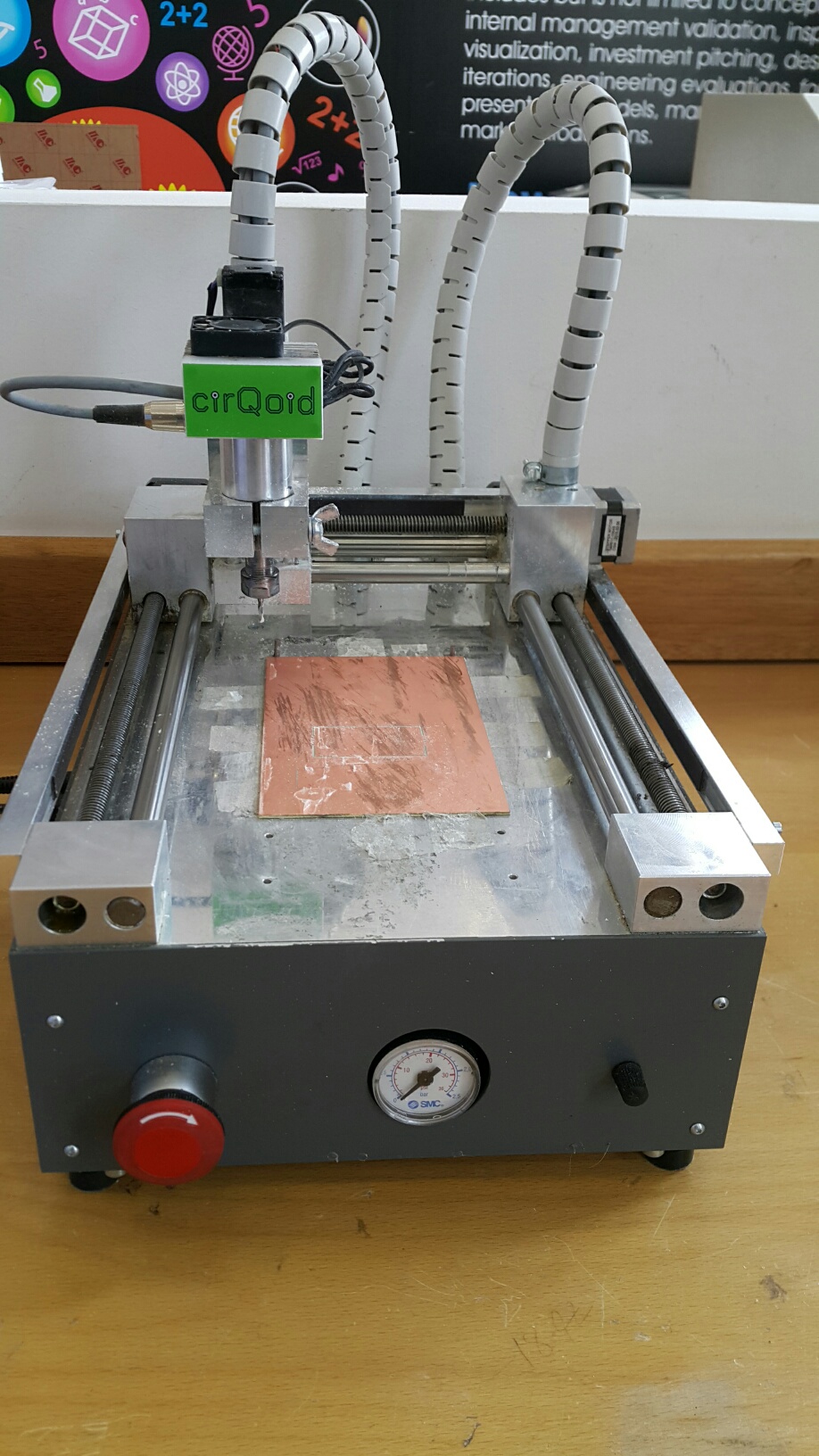
Making the in-circuit programming by milling the PCB using the milling machine. It requires a combination of soft and hard adjustments.
By using the X-Axis and the Y-Axis to set the area and size of the PCB required. The Z-Axis set the deph of the pin, either deep for full cutting or normal just for creating the routes.
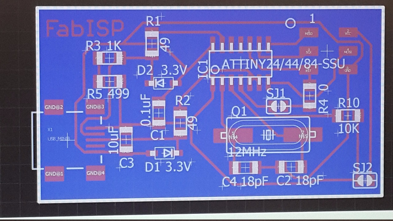
The map which is found on week four's fablab archive, shows the way on how to implement the PCB with all its parts stuffed on it. The parts are having names to recognize during the search process.
PCB production process
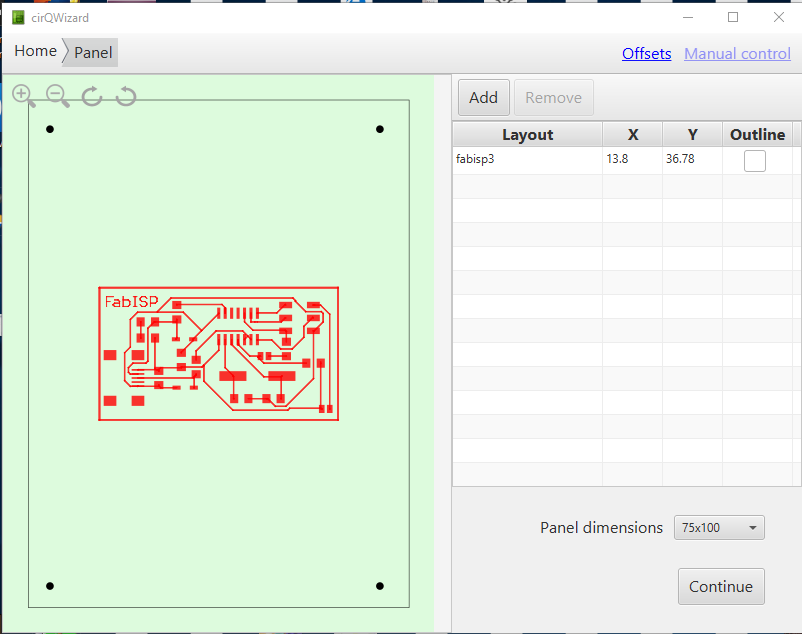
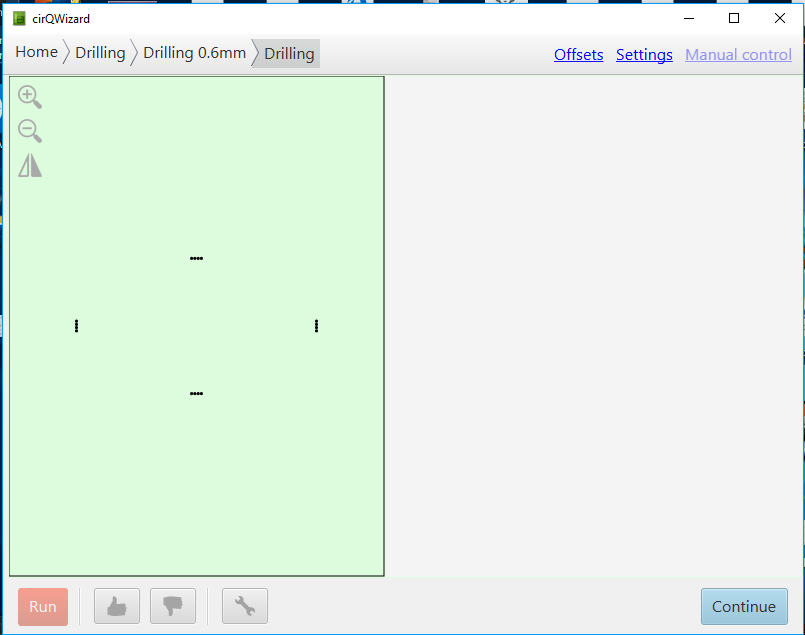
First, open the your CMP file inside the cirQWizard software.
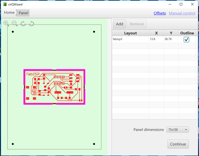
On the right side, press on the Outline button to highlight your board. The board is highlighted and ready to be produced.
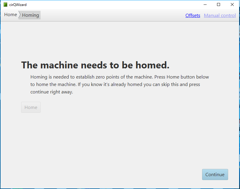
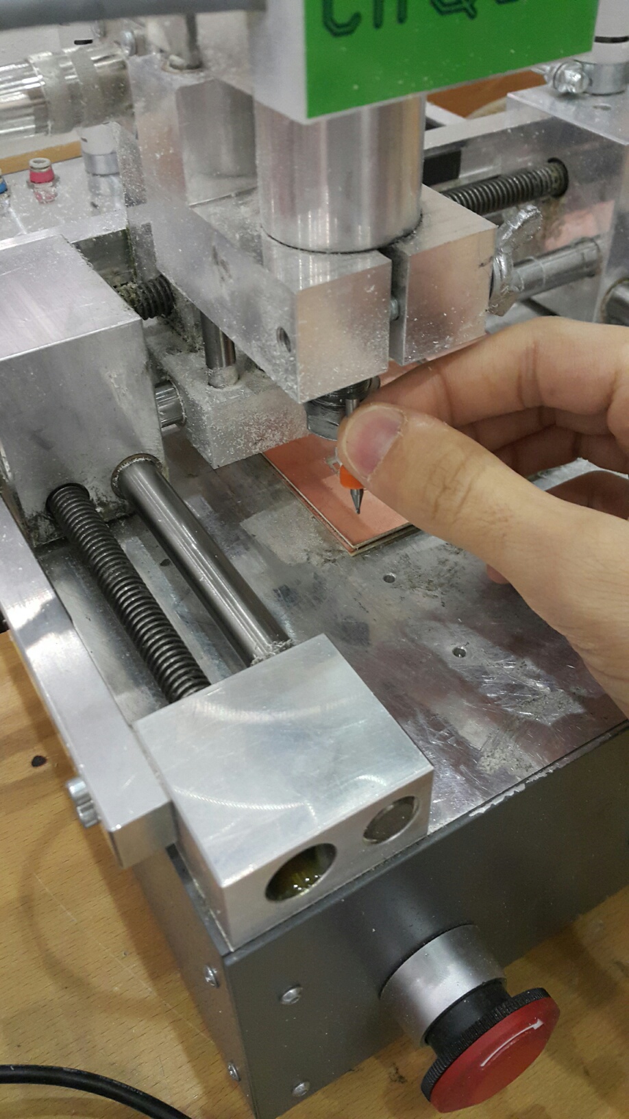
The bit of the machine needs to be on the zero position which is home in order to place the bit easly.
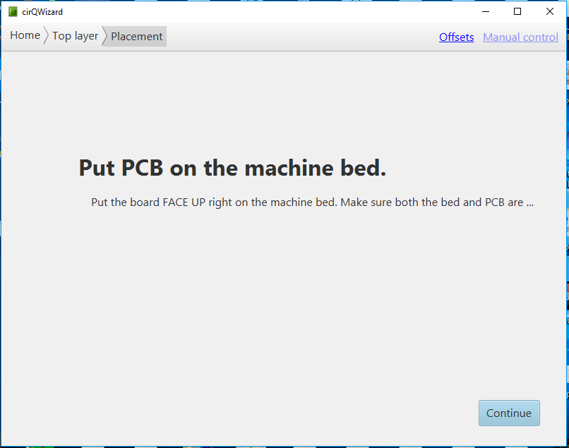
The PCB will be attached on the milling machine using a double face sticker to make it hold and not fall of while milling or cutting.
This is the bit head which is now on zero (home) position.
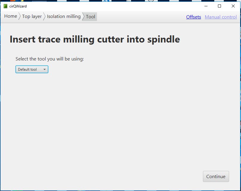
I need to choose the milling bit in this step by selecting on the default tool (0.2mm).
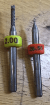
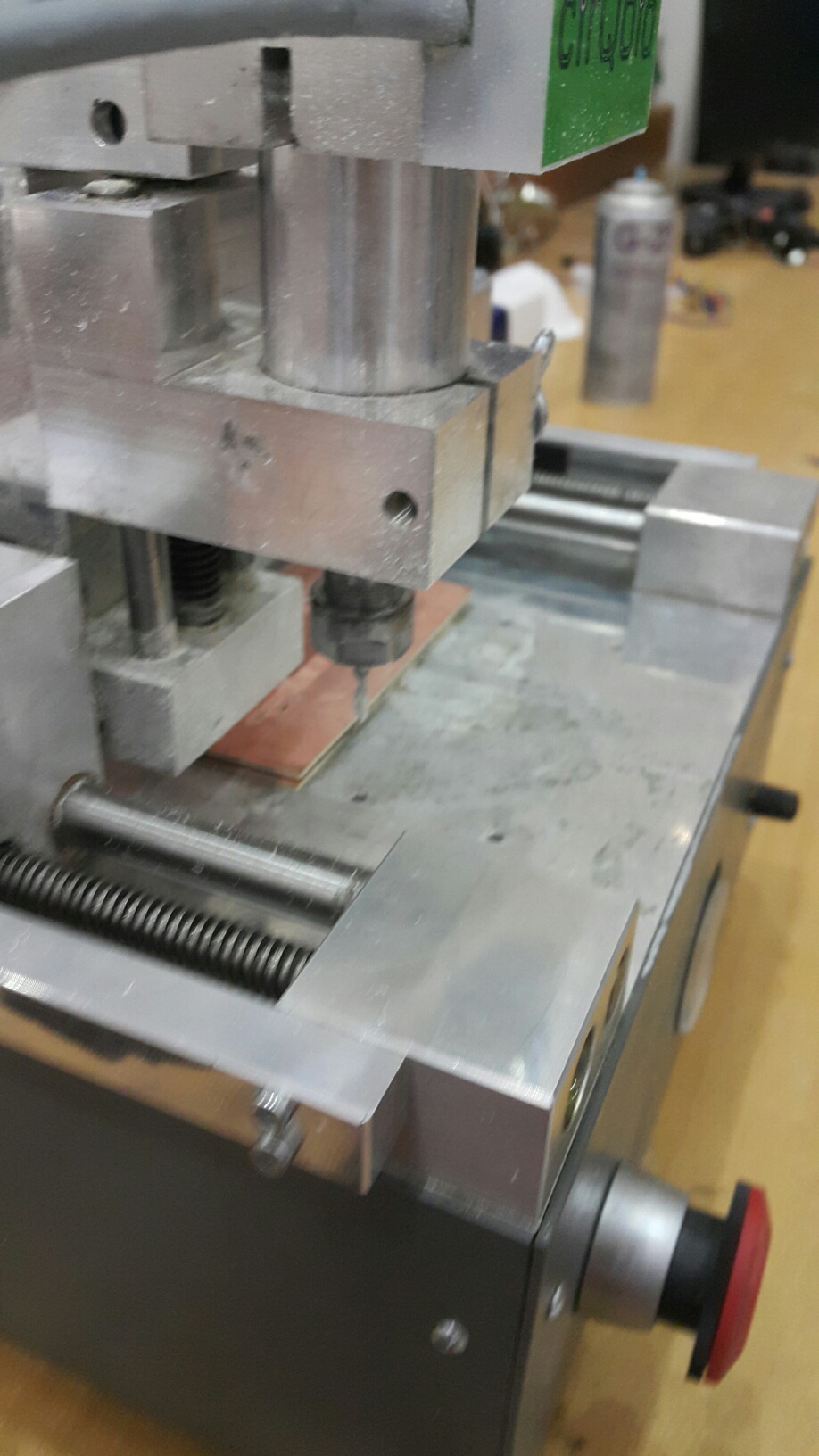
This is the milling tool to be placed on the bit head which is 0.2mm for milling.
It will be replaced here exactly and should be hold and make sure that it will not fall.
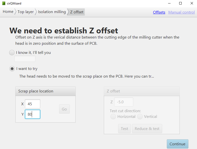
In this stage, i need to set the appropriate Z offset for the milling which is not high or deep. By testing, I chosed a position of X-45 , Y-80 and the Z has been set to -15. The deepness of the Z is the best for milling the board which is not too deep or high.
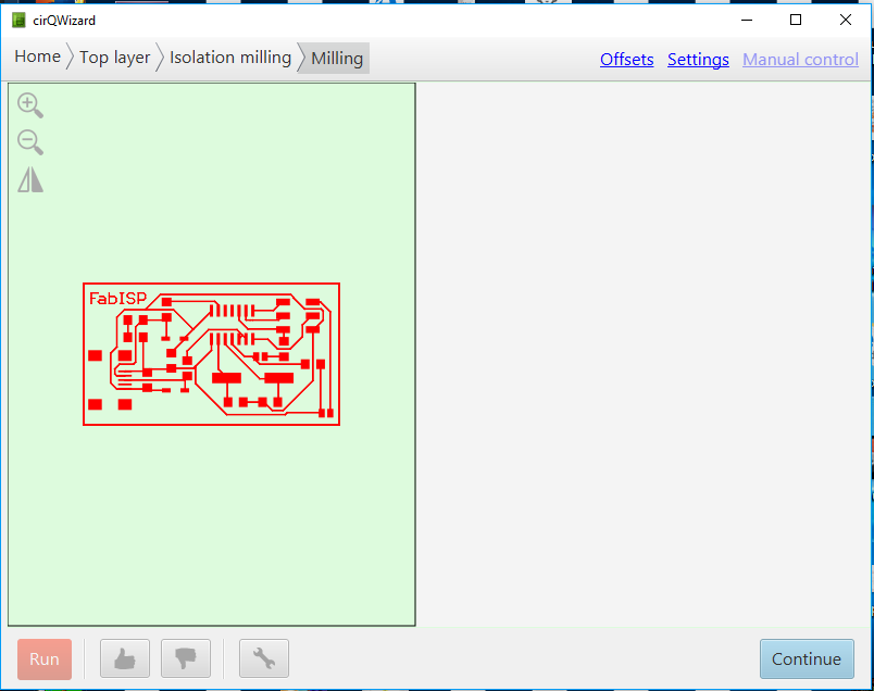
As I can see, this is the milling trace that machine will walk through. So to start the operation, press Run at the bottom. After it finishes, press continue
After the milling procedure finishes, the next stage is to cutting the board out by using a 2.0mm cutting tool. And then press the Run button. After it finishes the cutting operation, press continue.
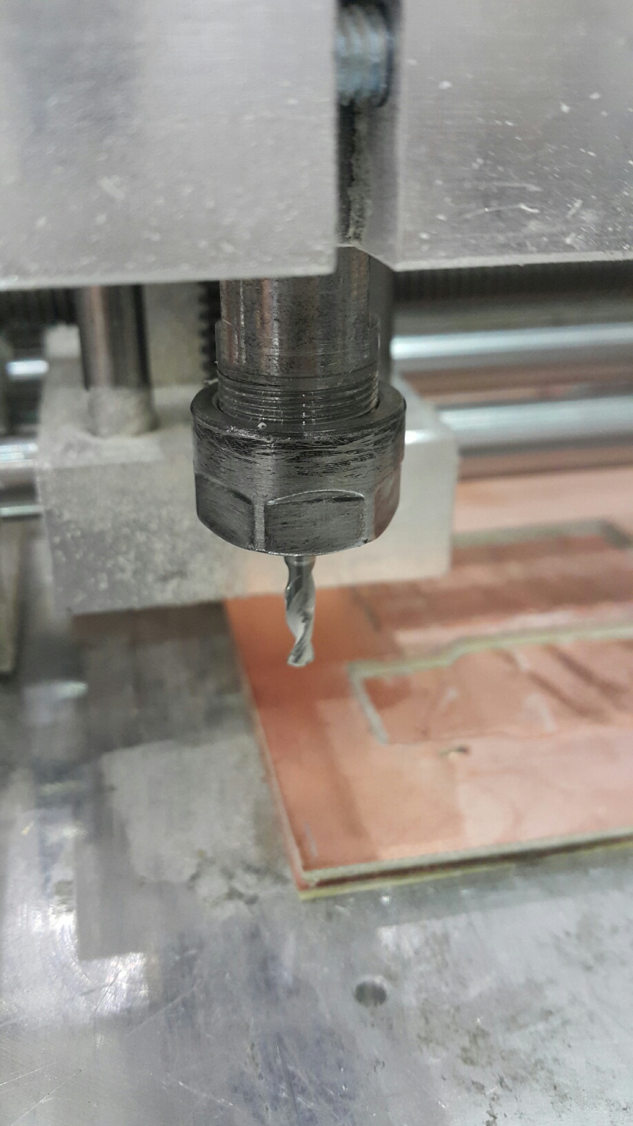
This is the 2.0 cutting tool to be replaced on the bit. Also make sure that it is tight enough.
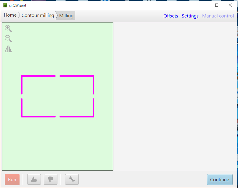
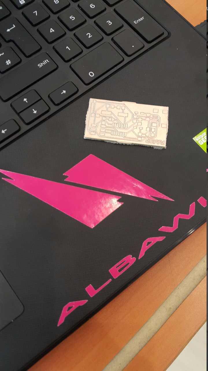
The cutting line will be this pink colored square. This is the outline of the PCB to be released from. This stage is to cut the PCB and brings it out. Now to press the Run button and let it run.
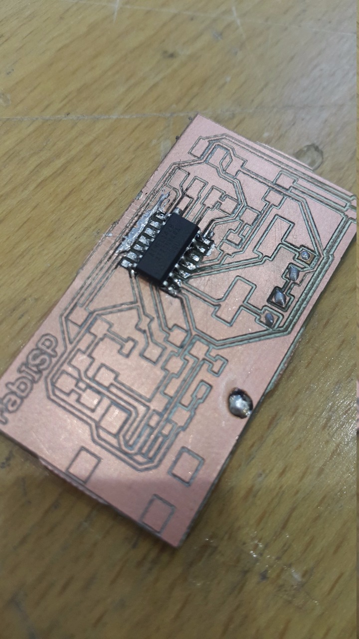
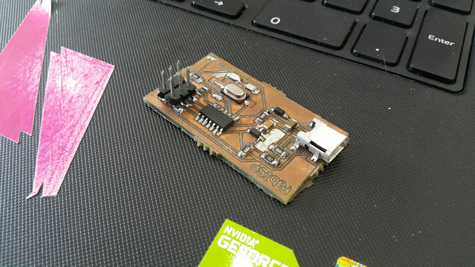
In this stage, we have to solder the components on this PCB.
Components used for soldering:
1- ATTiny 44 microcontroller
2- 1 Capacitor 1uF
3- 2 Capacitor 10 pF
4- 2 Resistor 100 ohm
5- 1 Resistor 499 ohm
6- 1 Resistor 1K ohm
7- 1 Resistor 10K
8- One 6 pin header 9- 1 USB connector
10- 2 Jumpers-0 ohm resistor
11- 1 crystal 20MHZ
12- Two Zener Diode 3.3 V
13- One USB mini cable
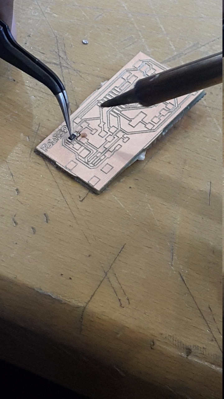
Stuffing and de-bugging are the most difficult part for me. To make the components of the PCB stick on top it is requires some skill. Sometimes your overheat the plate or create connecion with two routs together which will breach the circle.
By using the grabing tool, it will be easier to focus more on the plate due to stadiness. Also the glass amplifier would help making a clear image on where to focus on.
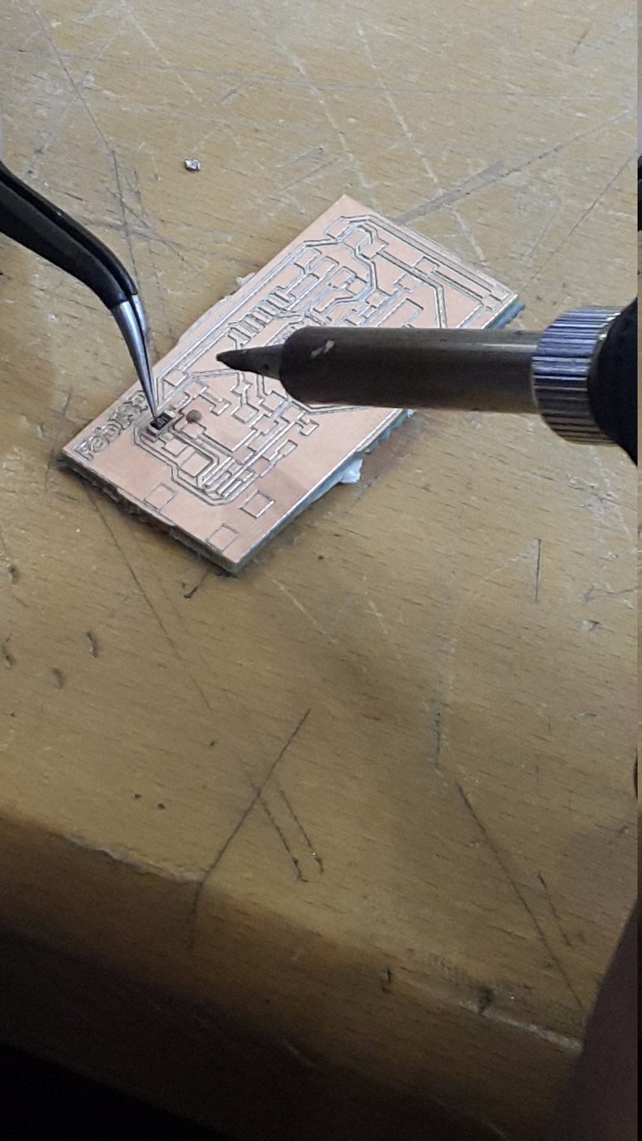
Once finishing stuffing some parts, there are some mistakes happen. By removing those parts, we can use the heater to heat the part we want to remove, and using the grabber we can remove it easily.
Programming Stage
By using ubunto, programming the ISB requires installing AVRdude for code communication.
1) First, openning the Terminal and start typing "sudo apt-get install flex byacc bison gcc libusb-dev avrdude"
2) Then, to install the gcc-avr which is the compiler, start typing "sudo apt-get install gcc-avr"
3) You will be asked to do this on your system so type yes "Y"
4) Now, you need to install the avr-libc which is the C library to be used for GCC and AVR microcontrollers, to install, type "sudo apt-get install avr-libc"
5) It is type to programm. So start typing these commands:-
a. "make clean"
b. "make hex"
c. "make fuse"
d. "make program"
Now your programm is successfully done.
Difficulties
The hardest part is the Criquid printing steps. They need to be well-known by practicing the sequence stages many times in order to get used to it.
Problem fixed
First, I did not heat the surface when attaching a component to be soldered. This is a very iportant tip to be done in order to attach the component with the surface. So both should be hot for the connection to be occured.
PCB Components mounting tutorial
This is a very simple guide on how to mount the components on the PCB with a certain way:-