Embedded Networking and Communications (WEEK Fifteen: MAY 15)
Assignment
Design and build a wired or wireless network connecting at least two processors.
This week, I will make three boards connected with each other using wires. The first board is the MASTER board that controls the other two boards which are the SLAVES. The master board has a switch and the slave boards have LED on them so that when we press the switch on the master board, the LEDs on the slave boards will light on.
What is Networking?
What is meant by networking, it is the the sharing and exchaning data within more than one device using something called data link such as cables, wires or routers.
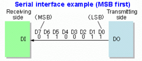
Serial Network
The serial communication is defined as the process of sending data one bit at a time with a sequential form over a communication channel.
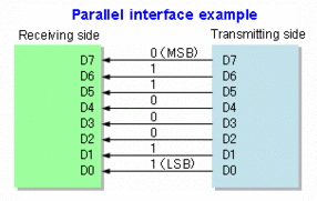
Parallel Network
The parallel network is define as the work that can be broken down into more than one subnetworks in a parallel form.
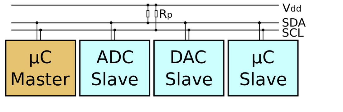
I2C Network
The I2C is defined as the Inter-integrated Circuit. And the protocol is a protocol allowing more than one slave to communicate with a master chip.
Eagle Software
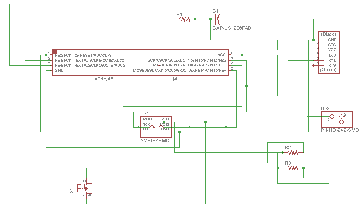
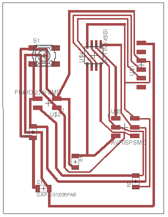
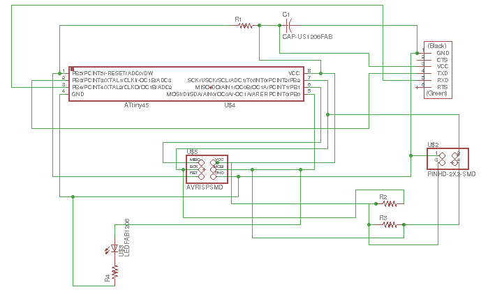
Master board design
This is the master schematic.
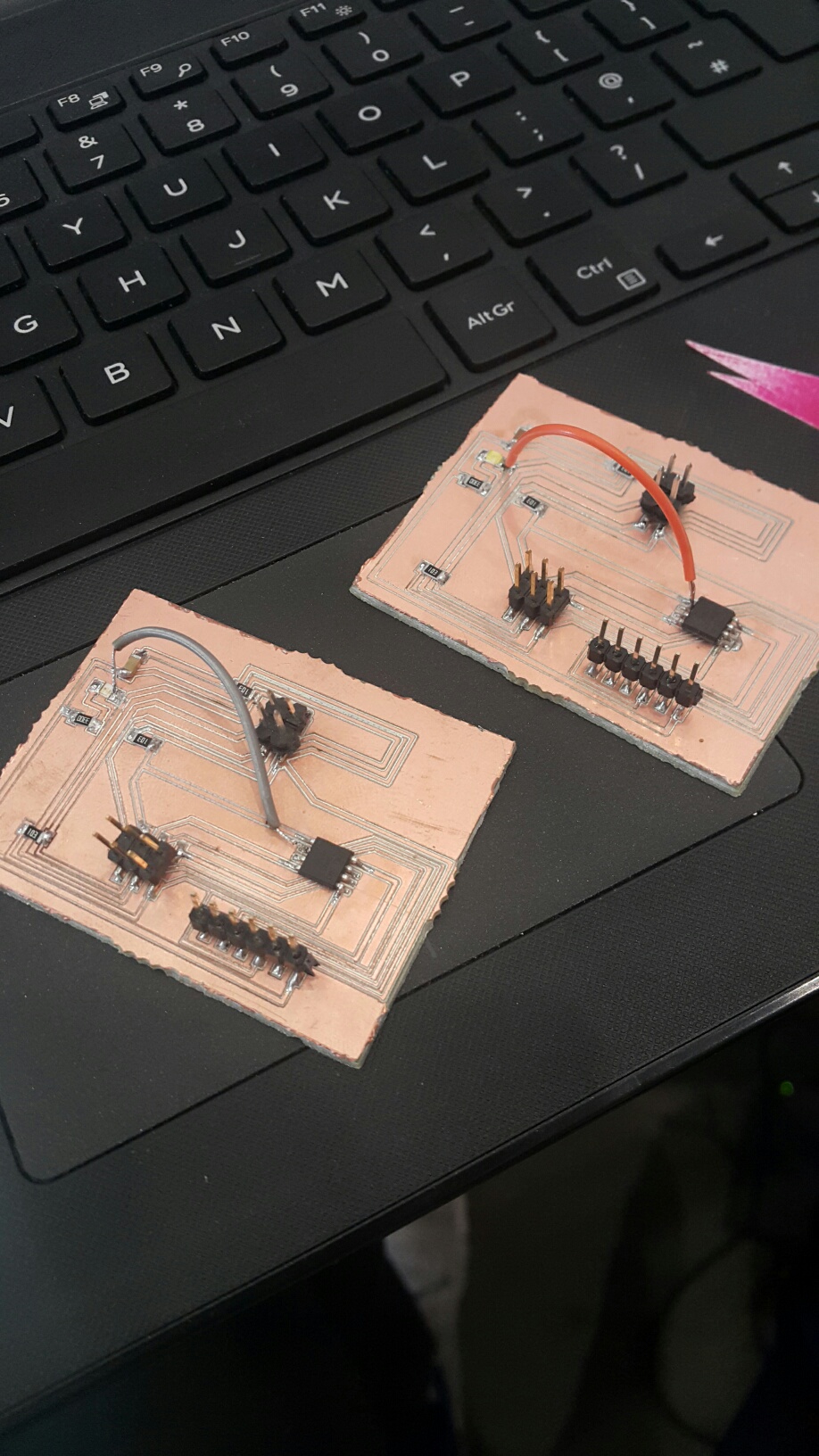
This is the master board. The power will go through it and transport it to the slave boards.
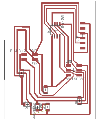
Slave board design
This is the slave schematic.
This is the slave board. It has an LED which will glow when programming it. I have used anoter slave board with the same design of this slave board.
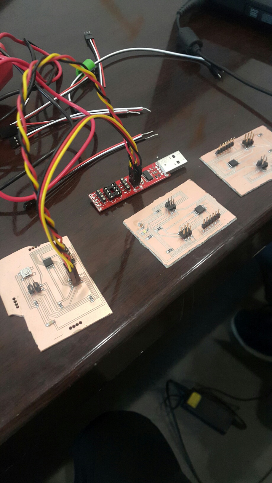
The Connection
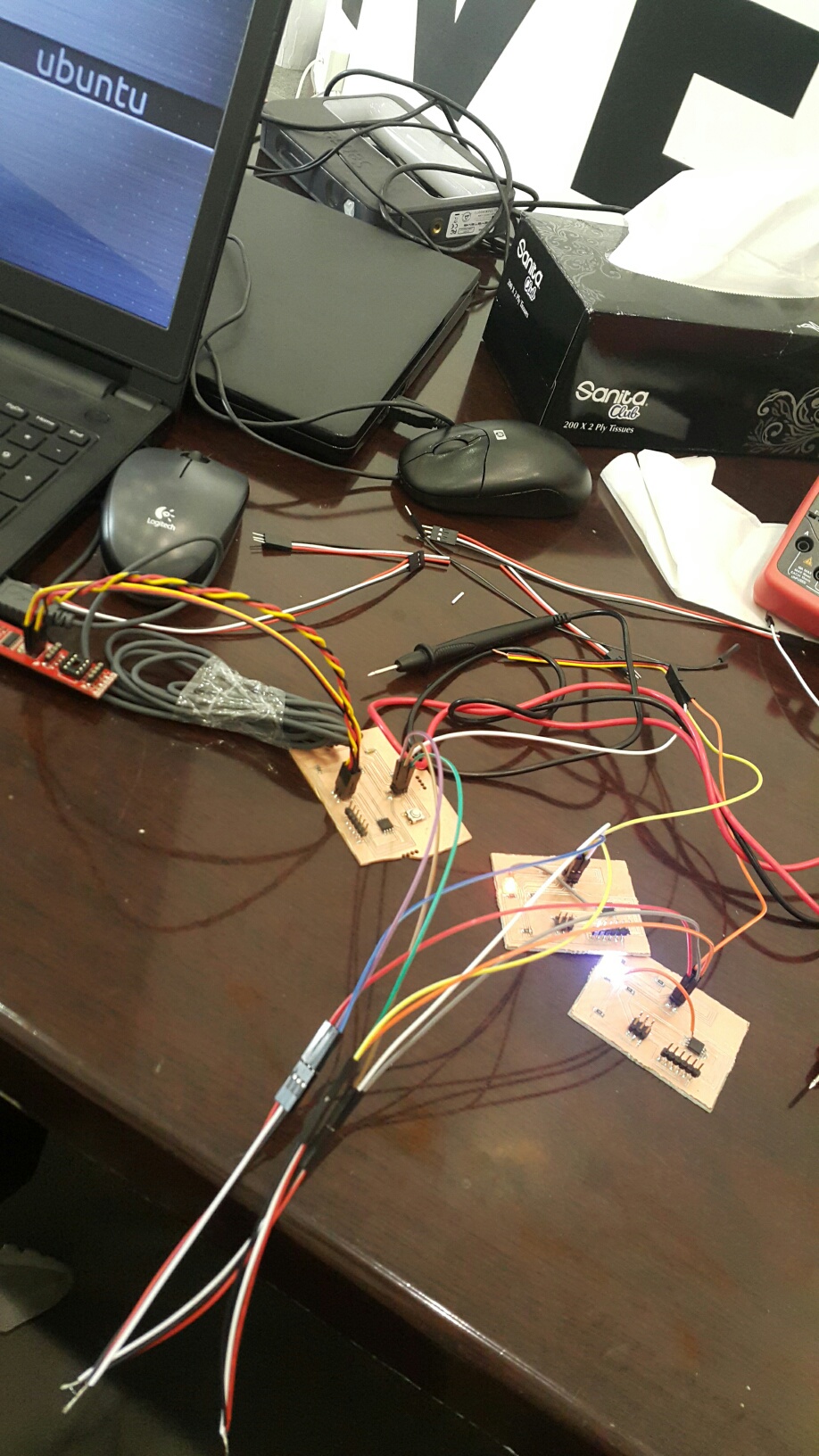
It is time to connect all the boards together using wires.
I have put wires from the LED to the microcontroller becuase of a schematic mistake
Master programming
This is the Master board code. For the arduino programming, first I download the master library. And I assign the address of two slave boards addresses and I program blink (slave 1) and wait a second blink (slave 2).
This is the slave board code, giving them a code name to identify both of them. before the programming, I have downloaded the TinyWireS.h library and I assigned the adress of the Slave 1 board as 0x1
#define output(directions, pin) (directions |= (1 << pin)) // set port direction for output
#define input(directions, pin) (directions &= (~(1 << pin))) // set port direction for input
#define set(port, pin) (port |= (1 << pin)) // set port pin
#define clear(port, pin) (port &= (~(1 << pin))) // clear port pin
#define LED_PIN PB4
#define I2C_SLAVE_ADDRESS 0x1 // Address of the slave 1
#include < TinyWireS.h>
void setup()
{
output(DDRB, LED_PIN);
clear(PORTB, LED_PIN);
TinyWireS.begin(I2C_SLAVE_ADDRESS); // join i2c network
}
void loop()
{
byte recd = 1;
if(TinyWireS.available()) {
recd = TinyWireS.receive();
if(recd == 1) {
clear(PORTB, LED_PIN);
} else {
set(PORTB, LED_PIN);
}
}
}
Slave 2 programming
Since this second board has the same design and function as the first slave board, the code will be the same for both But the address is diffirent, in here I gave 0x2.
#define output(directions, pin) (directions |= (1 << pin)) // set port direction for output
#define input(directions, pin) (directions &= (~(1 << pin))) // set port direction for input
#define set(port, pin) (port |= (1 << pin)) // set port pin
#define clear(port, pin) (port &= (~(1 << pin))) // clear port pin
#define LED_PIN PB4
#define I2C_SLAVE_ADDRESS 0x2 // Address of the slave 2
#include < TinyWireS.h>
void setup()
{
output(DDRB, LED_PIN);
clear(PORTB, LED_PIN);
TinyWireS.begin(I2C_SLAVE_ADDRESS); // join i2c network
}
void loop()
{
byte recd = 1;
if(TinyWireS.available()) {
recd = TinyWireS.receive();
if(recd == 1) {
clear(PORTB, LED_PIN);
} else {
set(PORTB, LED_PIN);
}
}
}
Connecting the boards
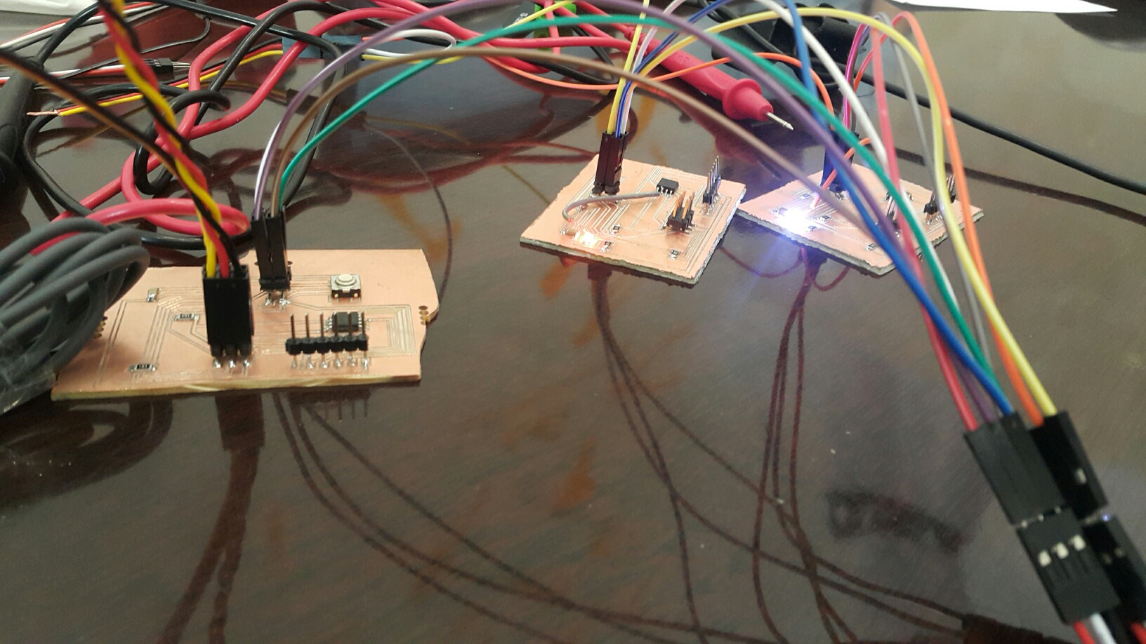
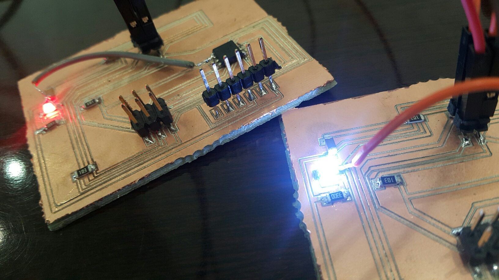
The boards are successfuly connected and the lights are glowing.
I have to be careful connecting the wires with the board ports (SDA, SCL, GND and VCC)
This is very good to make a project with different parts to make it easier. If a huge project with only one board, there will be a lot of problems with wires and shorts and may not handle the power.