
The Microcontroller
The microcontroller is the brain of the circuit board, It controls the power, ditributes the electricity and operates the output devices. The microcontoller can be programmed to make any functionality and depends on the device by using the code system.
The microcontoller is also called "MCU" and it is small in size to be put on a single integrated circuit. These microcontrollers can controll many machines such as automobile engines, smartphones, heavey machinary and home devices.
The first microcontroller was made in 1971 which is called 4-bit intel 4004. It is a very simple processor that is enough to operate basic devices. since that year untill now, mcrocontrollers became more developed and complicated.
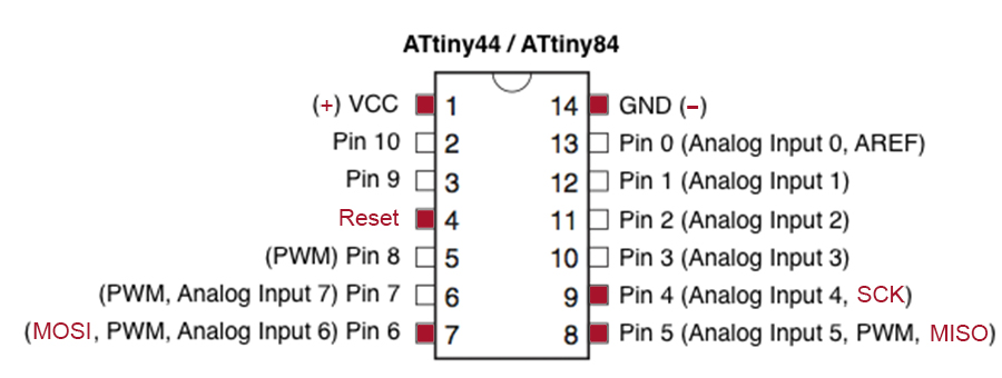
1) GND (Ground): Common Ground
2) RST (Reset): To enable In-System Programming, the target AVR Reset must be kept active. To simplify this, the In-System Programmer should control the target AVR Reset
3) SCK (Serial Clock): Programming clock, generated by the In-System Programmer (Master)
4) MOSI (Master Out - Slave In ): Communication line from In-System Programmer (Master) to target AVR being programmed (Slave )
5) MISO (Master In - Slave Out): Communication line from target AVR (Slave) to In- System Programmer (Master)
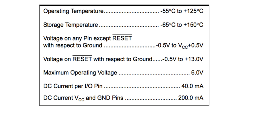
Attiny Measurements
ARDUINO
A company called Arduino manufactured single board microcontrollers and microcontroller that uses a variety of microprocessors and controllers. They have set a name to it which is the same name of the company "Adruino"
In this week, I will use an Arduino board to program a lighting LED. I will demonstrate the steps of creating the circuit and the programming.
5 steps to get started
1. Learn C language
2. Learn Some Basic Electronics
3. Get the Basic Equipment
4. Choose a Microcontroller and Toolchain
5. Pick Components and Dig into Their Datasheets
Arduino Board program test
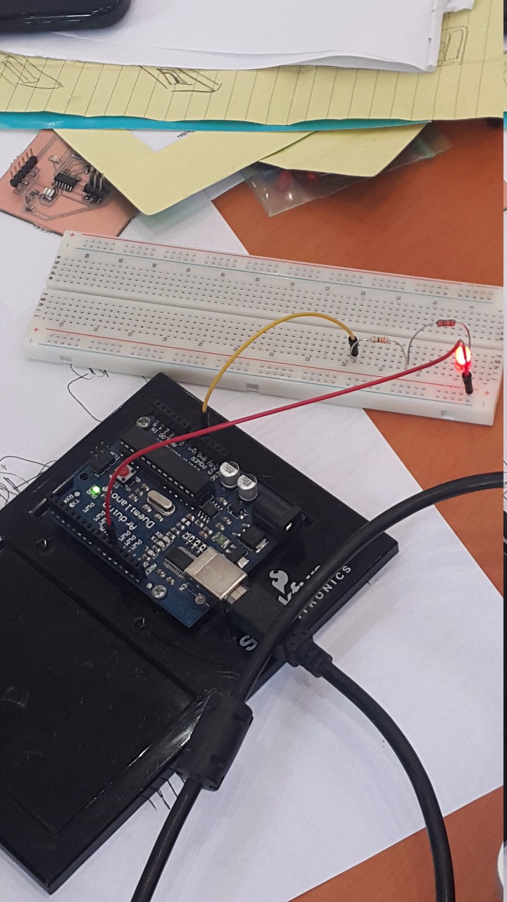
This circut has been done using ready made arduino board with wires, resistros and LEDs. Any circut in the world starts from (+) and ends up with (-). In this circut, we have started with the (+) by plugging on number 13 on the board using the red wire shown in the above image.
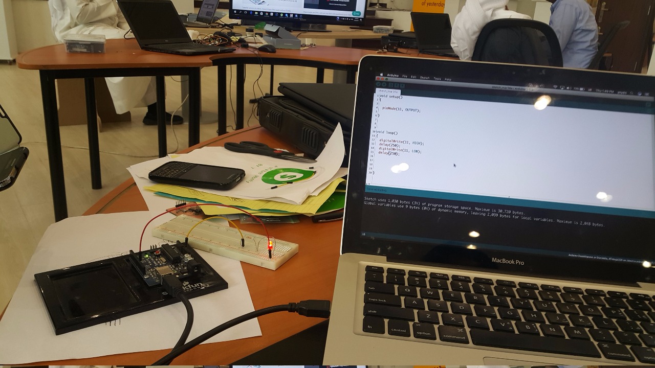
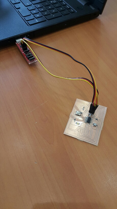
We will make the LED glow and close using the C language. First we will plug the wire from the board to the computer and open the Arduino software. We will put the following code to create the action that we want from the LED. Arduino programming steps
The LED will now light up and close whenever we enter the code and make it function.
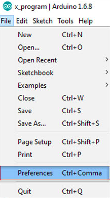
First of all, opening the arduino programming application, then pressing on File/Preferences.
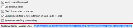
Into the additional boards manager URLs box, type
"https://raw.githubusercontent.com/damellis/attiny/ide-1.6.x-boards-manager/package_damellis_attiny_index.json i>"
Then press OK
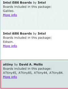
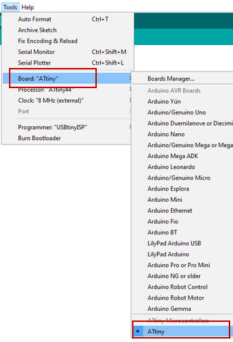
Now to go Tools/Boards Manager PCB program test
Scroll down and find the attiny box which includes all the attinies by David A. Mellis.
Select it and press install.
Now you are ready to program using the attiny microcontroller.
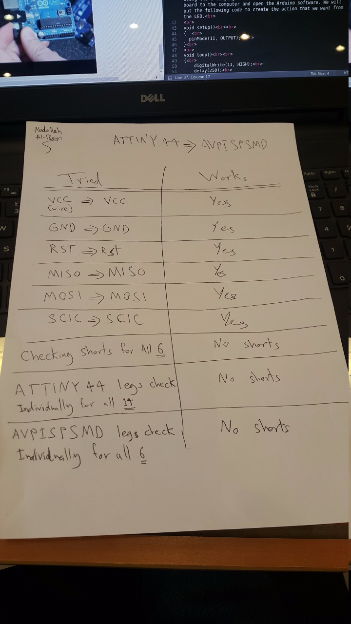
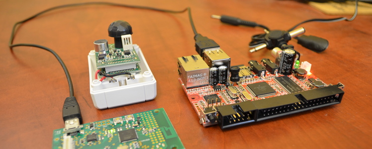
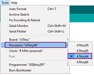
This way of testing the circut before continuing, is one of the best becuase its simplicity and clear enough to know where the problem is. By putting two colums (Tired) and (Works) to demonstrate east unit of the circut components wither they work or not. For this test, we are showing the connection of the ATTINY44 and the AVPISPSMD components. They seem to work fine. Afterwards, we do this mechanism for the other components of the circuts.
Board One (FALURE)
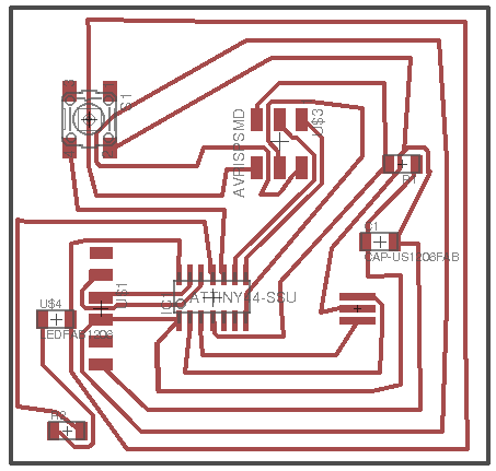
This board was from week six and i want to program it. But i figured out that there were something missing, which is the VCC route. I did not draw it in the schematic stage of the board. So the power will not go though the board and light the LED. So this is a falure attempt.
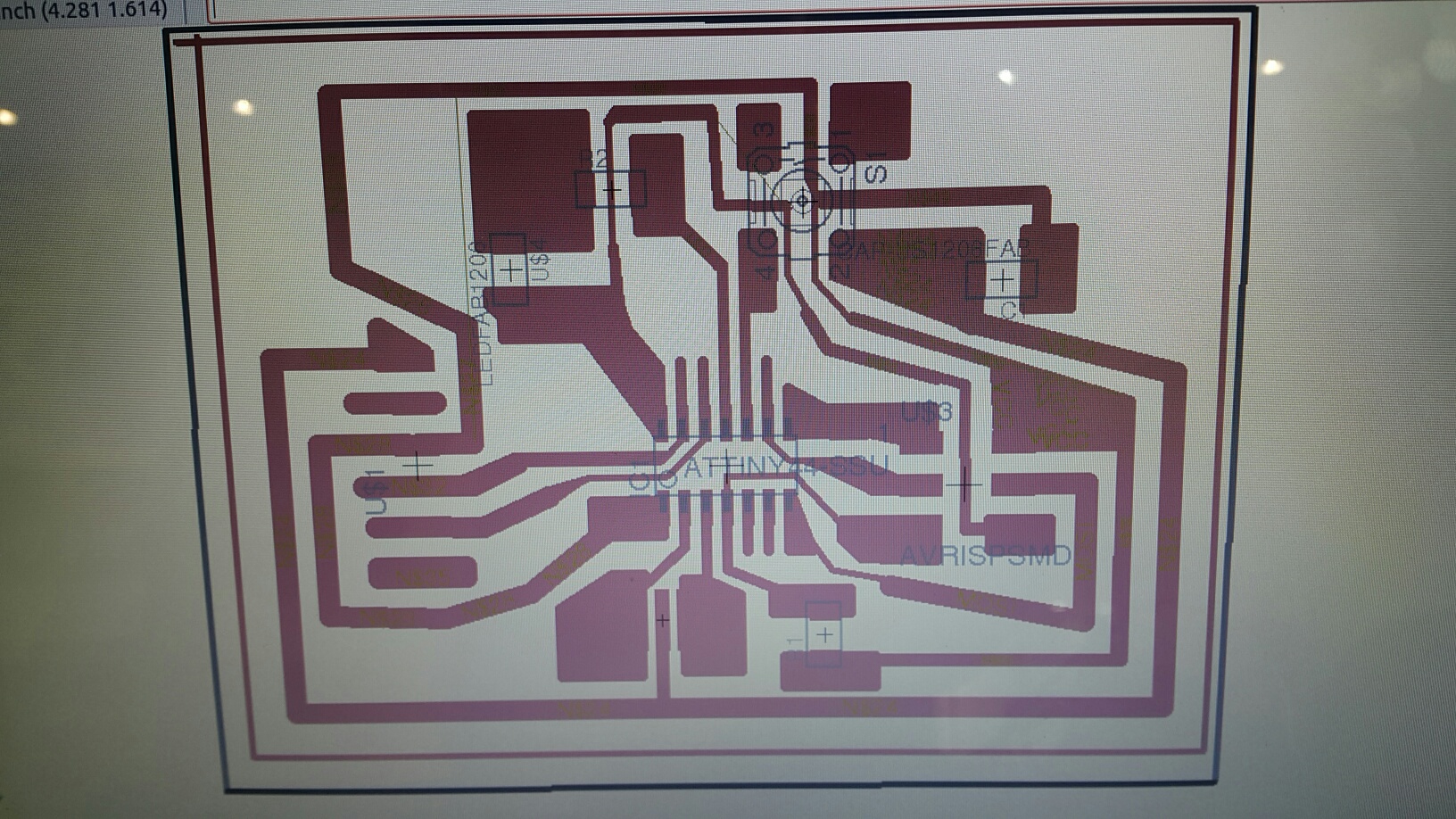
Board Two (FALURE)
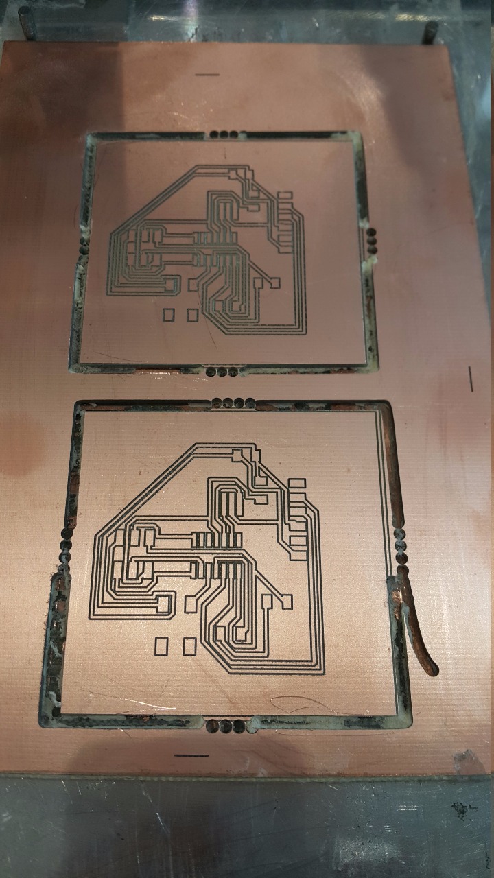
The idea of this board is to increase the thikness of the routes. This will create a better chance for the board to work successfully due to the power supply which will get flowing in the routes of the board. If it is thin, i may not work. But this board failed to get created due to the cutting procedures. The mailing machine cannot cut it becuase of the routes are touching the borders of the board and the machine will not successfully do it without cutting the whole border with it so, this board is a falure too.
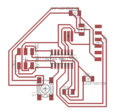
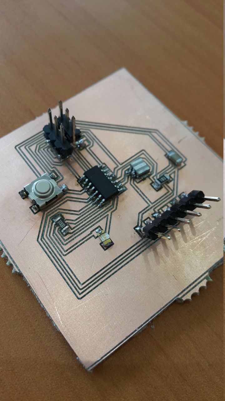
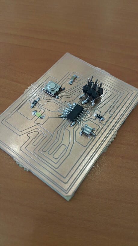
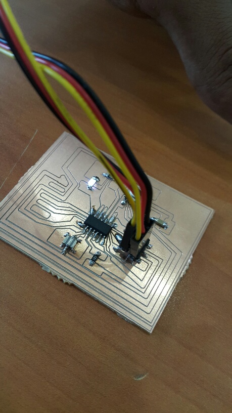
Board Three (SUCCESS) Ready to be programmed. Programming
This time, the board is perfect in size, route thikness, and fully adjusted manually. The LED lighted up successfuly as it is shown in the picture above. The video will demonstrate more about the LED and it's lighting.
Download Files Embedded Programming success This is a sample my LED PCB Board:-
Now write down the below code.
Programming Code
void setup()
{
pinMode(11, OUTPUT);
}
void loop()
{
digitalWrite(11, HIGH);
delay(250);
digitalWrite(11, LOW);
delay(250);
}
Board 1
Board 2
Board 3