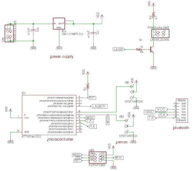
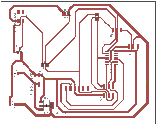
Final Project (16th June 2017)


About Project


A laser that can detect any location or object inside the room or hall. This happens by using a mobile application and choosing the location or object that you want. The laser device is attached on the roof or any other suitable place, and it will start pointing at the chosen location showing where it is. It is useful inside rooms at home or work, kitchens, garages and workshops.


Rough Sketch

webpage


The components used

1) Laser Beam
2) Servos
3) Attitiny
4) Bluetooth HC-05
5) LEDs
6) Jumper Wires
7) 4xAA holder
8) AA batteries
9) JST connectors -female
10) JST conectors -male
11) 5V Regulator
12) Establishing Caps

The total cost of the materials and components will be approximately $75.00 which is optimistic and affordable to make the replications.

The process, what I am using in my final project

Computer-Controlled Cutting
3D Scanning and Printing

Embedded Programming

Electronic Design

Application Development


Electronic Design

Input

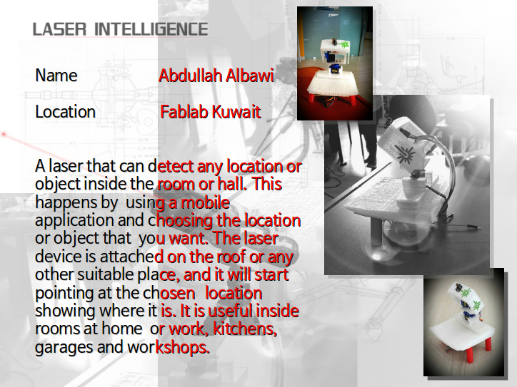
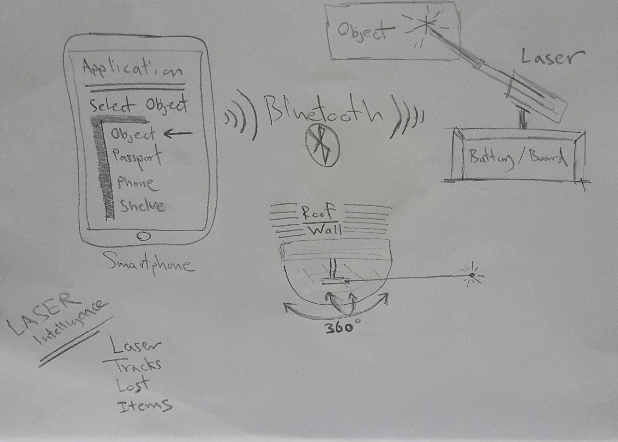
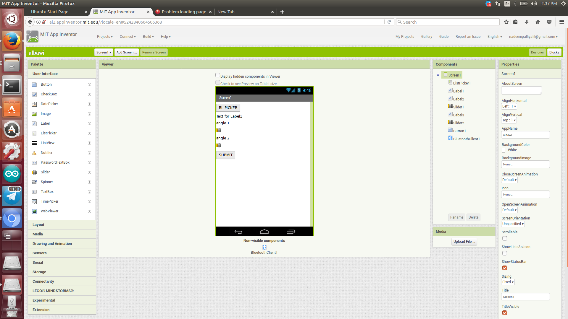
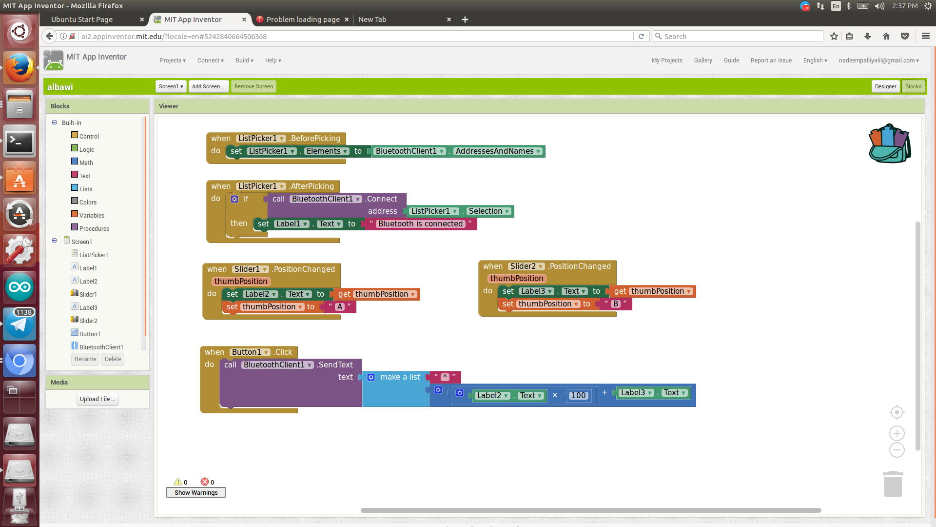
For the input, I have used a bluetooth device. This bluetooth device will be connected using a smartphone and an application to control the PCB to make the device function. The application contains two buttons and two sliders, bluetooth connection button, servo A slider, servo B slider and the Submit button.

Output

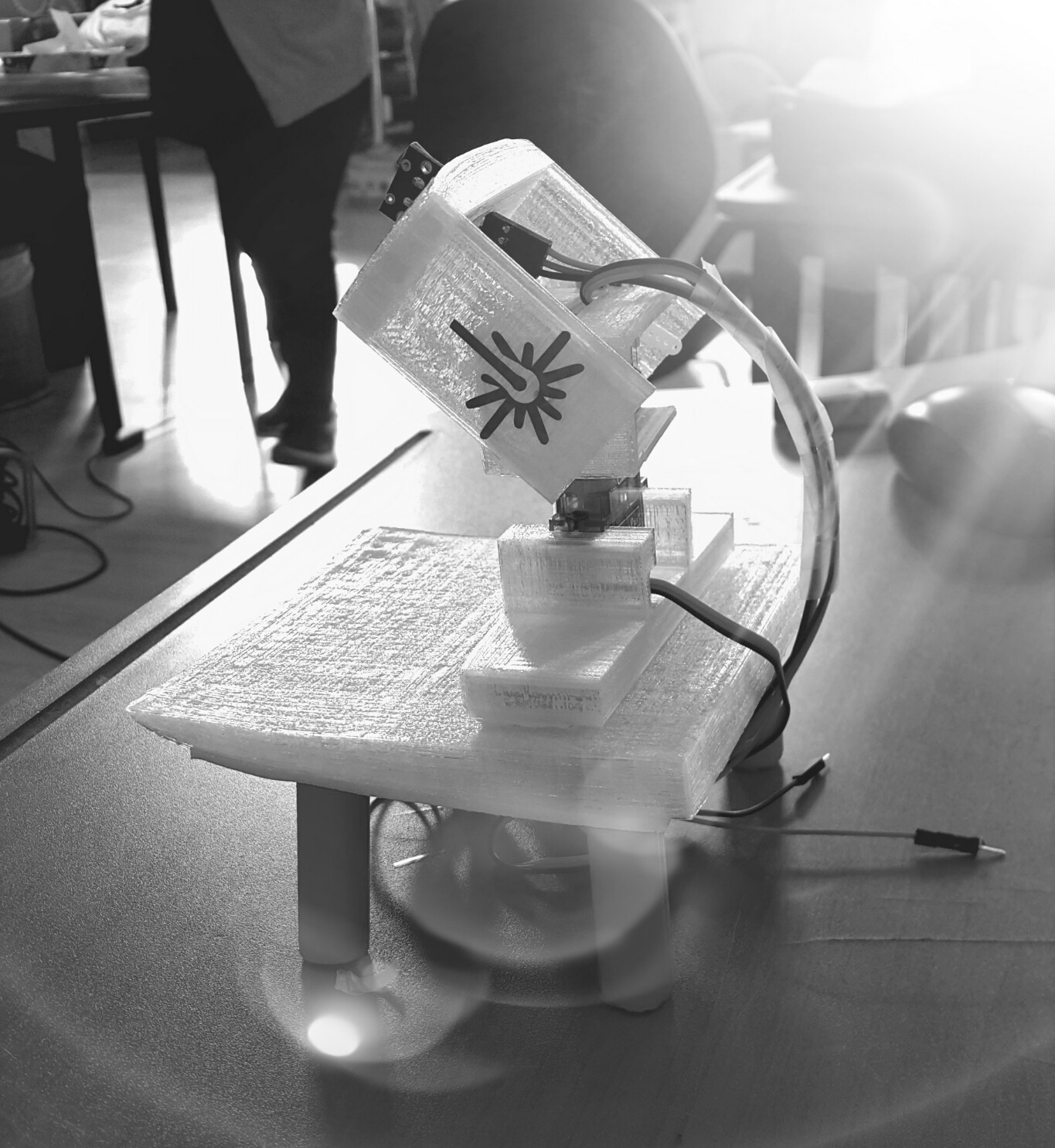
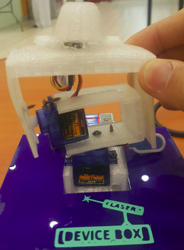
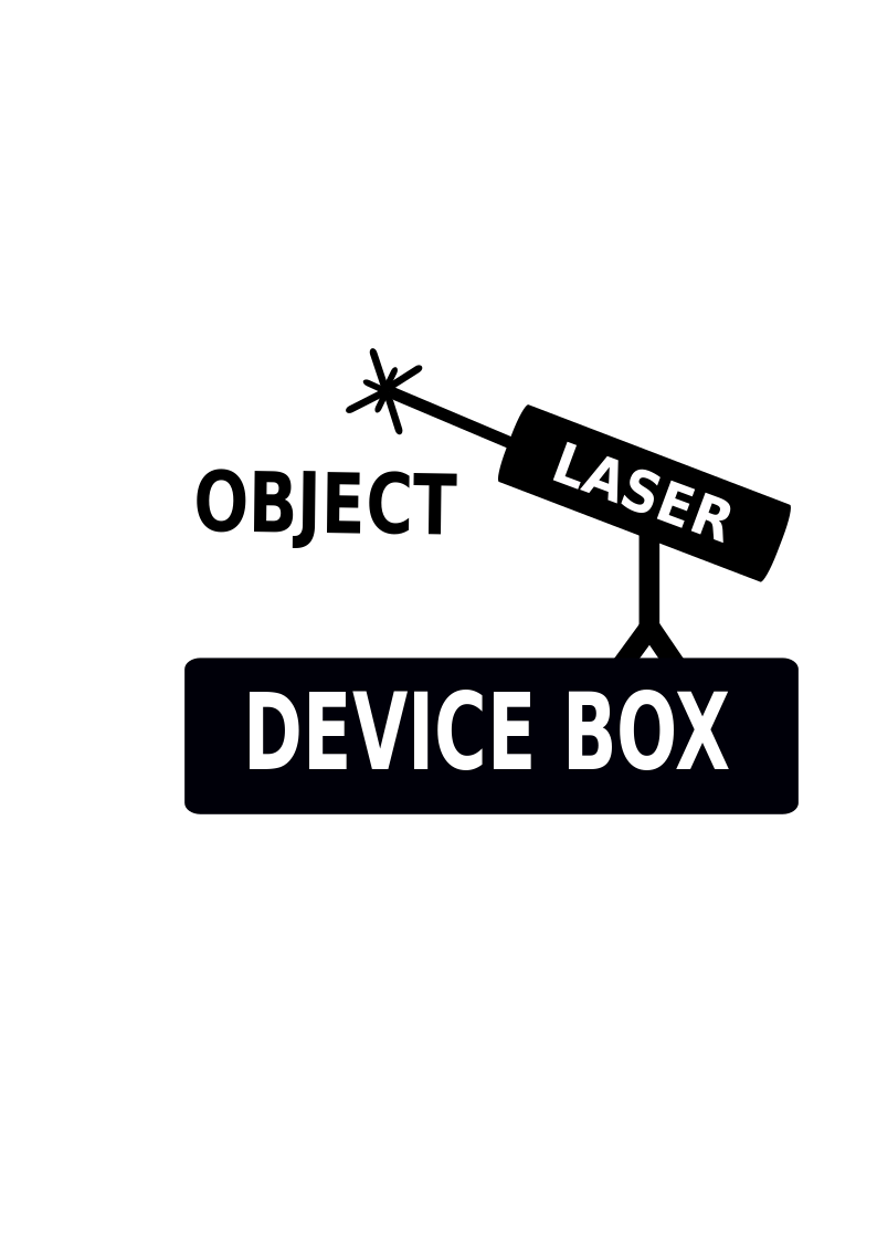
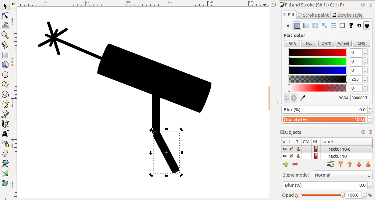
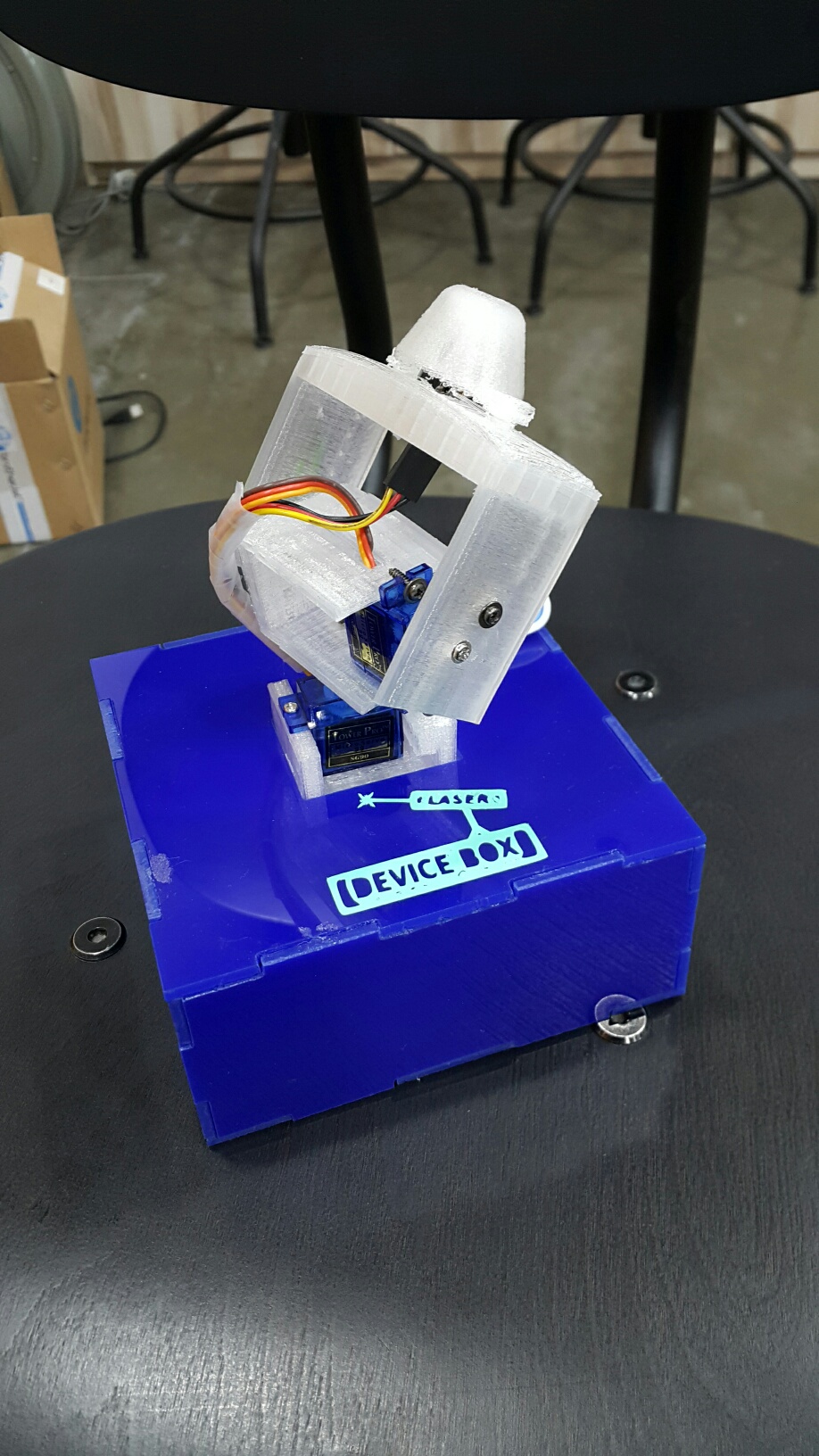
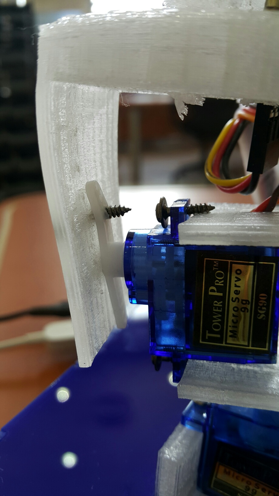
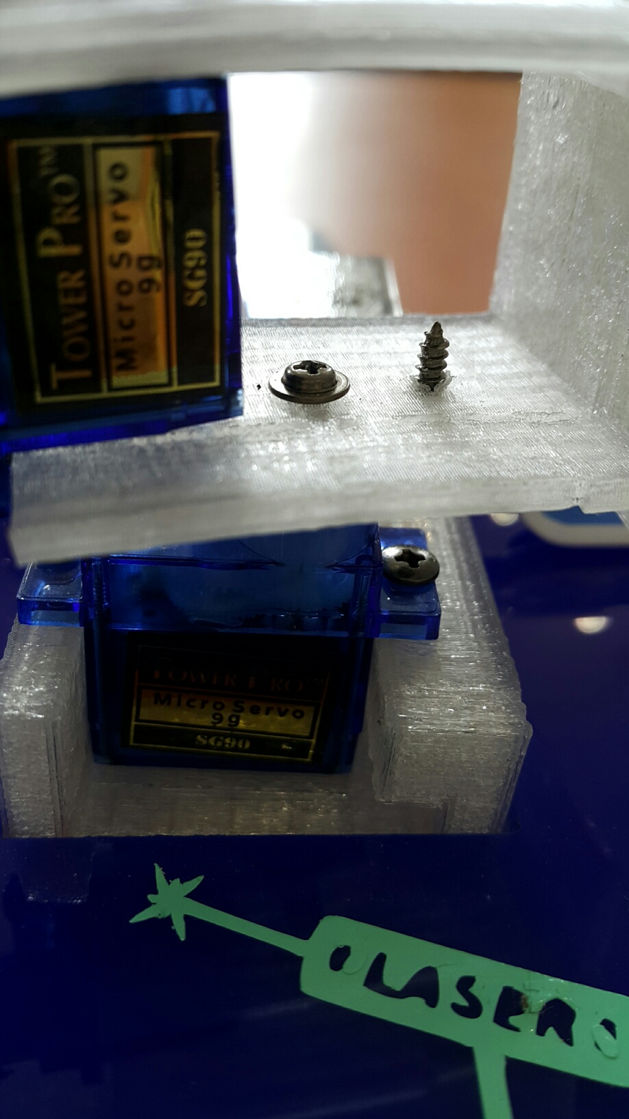
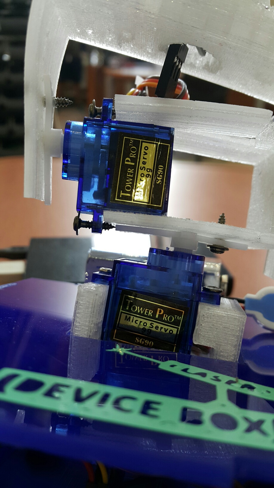
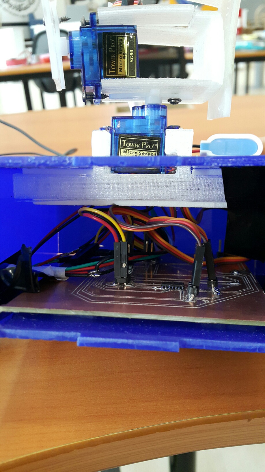
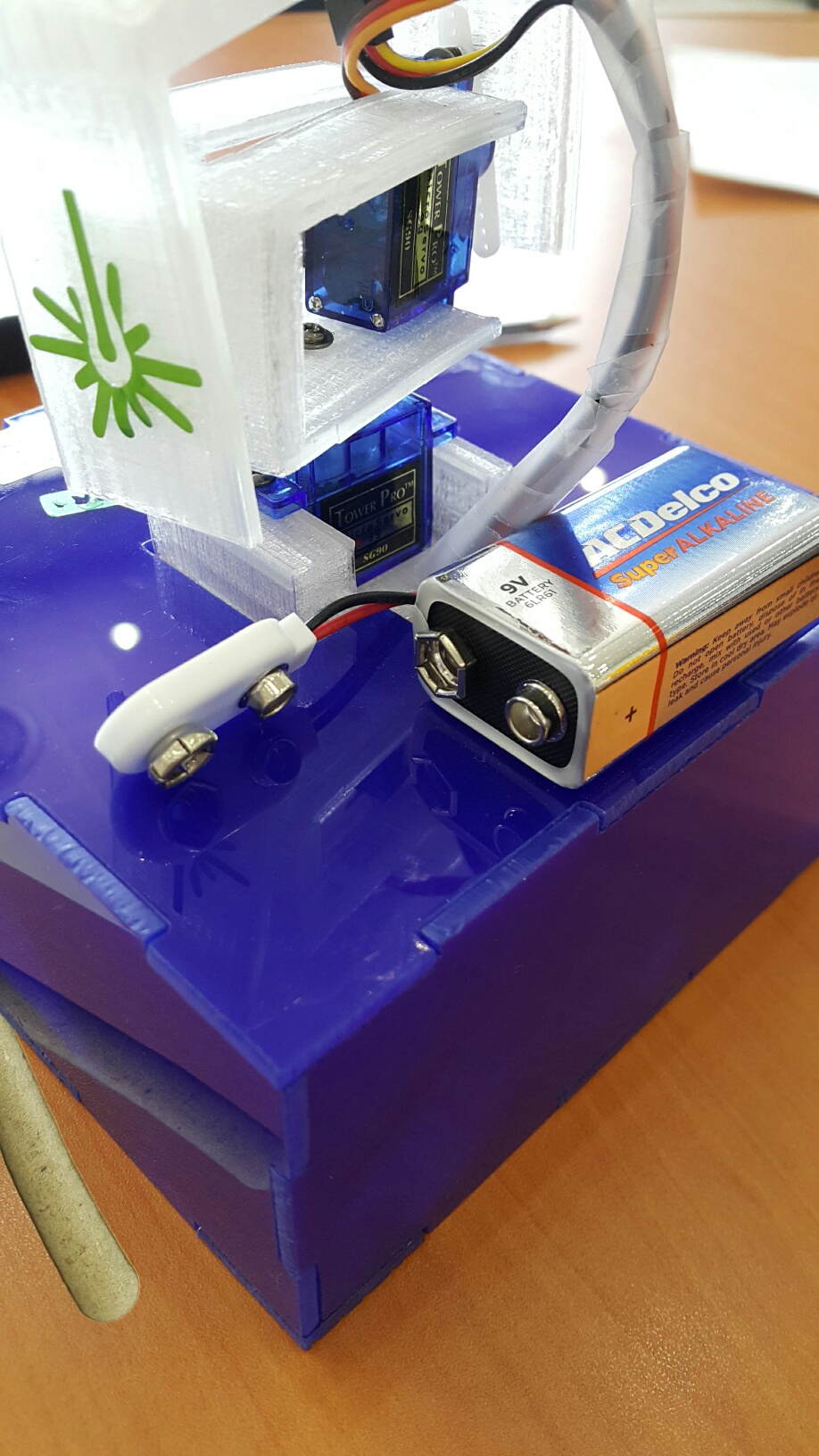
For the output, there are two devices which are the servos and the laser. For the servos, they are exist to make a 180*360 degree movement with is a half moon. To create that, the two servos are connected together with the 3D printed holder. They both move around to create a combination. The first servo will move 360 degrees, and the second servo will move 180 degrees according to the what we adjusted on the application.
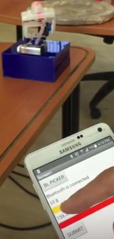
Ones they have moved into the position, the other output component which is the laser will start to light and point at the certain object.


How to interface

As we said, The application contains two buttons and two sliders,
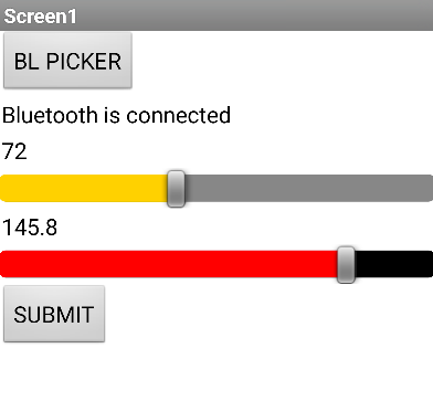
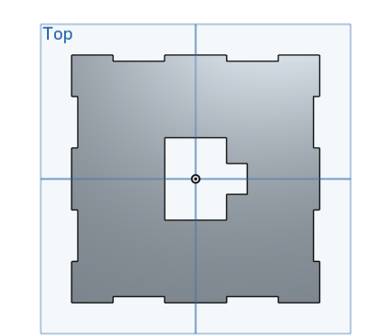
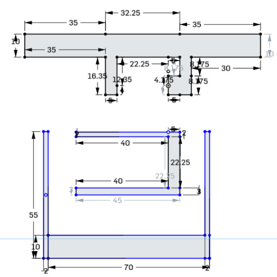
1) bluetooth connection button
2) servo one slider
3) servo two slider
4) Submit button

First we press the bluetooth connection button "BL PICKER" and power up the bluetooth device on the project to make the bluetooth connection. And then, we adjust the two sliders on the demanded position, and finally press "SUBMIT". The command will be given to the device and create the movement.


Electronic Design


This schematic has a lot of components and connectiong due to the project features themselves. The project has more than one function. This is why the board will be crowded but there will be no problem. The organizing of the board is well done.


This is a big board due to many components needed to be put on it which are servos, bluetooth, microcontroller and laser and power supply.


This is the hero shot of this step which is the final PCB for my project.


Programming

#include //for Bluetooth
#include "SoftwareServo.h" // servo

#define servo1 7
#define servo2 6
#define laser 5

int pos1 = 0; //represent present position servo1
int pos2 = 0; //represent present position servo2
int tpos = 0;
int tpos1 = 0; //represent present position servo1
int tpos2 = 0; //represent target position servo2


SoftwareSerial mySerial(3, 4); // RX, TX

SoftwareServo myservo1;
SoftwareServo myservo2;

char c;
String str;
void setup() {
pinMode(laser, OUTPUT);
myservo1.attach(servo1);
myservo2.attach(servo2);

//go home
for (; pos1 > 0; pos1 -= 2)
{
myservo1.write(pos1);
delay(15);
SoftwareServo::refresh();
}

for (; pos2 > 0; pos2 -= 2)
{
myservo2.write(pos2);
delay(15);
SoftwareServo::refresh();
}
mySerial.begin(9600);
}
void loop() { // run over and over

while (mySerial.available() <= 0);//wait till a data received c = mySerial.read();
if (c == '*') {
while (mySerial.available() <= 0);
str = mySerial.readString();
delay(200);
tpos = str.toInt();
tpos1 = tpos / 100;
tpos2 = tpos % 100;//reminder
mySerial.println(tpos);


for (; pos1 > tpos1; pos1 -= 2)
{
myservo1.write(pos1);
delay(15);
SoftwareServo::refresh();
}

for (; pos2 > tpos2; pos2 -= 2)
{
myservo2.write(pos2);
delay(15);
SoftwareServo::refresh();
}


for (; pos1 < tpos1; pos1 += 2)
{
myservo1.write(pos1);
delay(15);
SoftwareServo::refresh();
}
for (; pos2 < tpos2; pos2 += 2)
{
myservo2.write(pos2);
delay(15);
SoftwareServo::refresh();
}
digitalWrite(laser,HIGH);
delay(5000);
digitalWrite(laser,LOW);
}
}

Application Development

I developed the application using MIT application development.

I have put two buttons and two sliders for the servo angles. They are arranged by the steps from top to bottom.

The it functions, I connect the application with the device by choosing the "BL PICKER" to choose the bluetooth device. Then choose the angle wanted using the two sliders. Then press "SUBMIT". The laser will start moving around to the chosen angle. Ones it stops, the laser will start pointing the light towards the object for 5 seconds and then it will turn off. The function is now fully done. To start again you have to choose the angle again and press the "SUBMIT" button.


Design and Sketch

Box Design

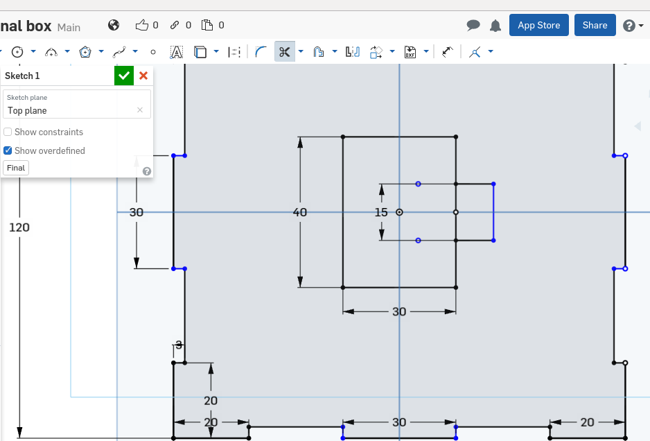
The box has been made using the Onshape application. Sketching the box is easy. First, drawing a square using the box tool and then giving it lines on the edges according to the measurements wanted. After that we will but the lines and create the space and teeth shown in the below picture.
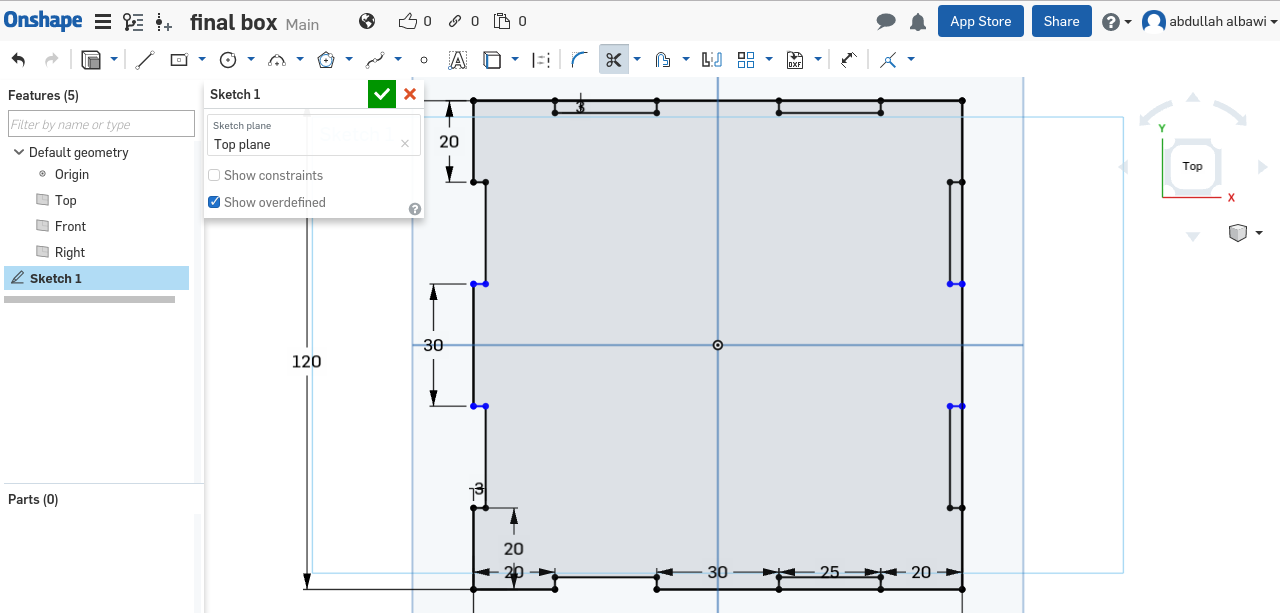

The box size is 120mm width, and 55mm height. The acrelyc thickness is 3mm so I did my measurements to make the box fit and solid.


Now to create the hole for the laser to be exposed, I draw a square in the middle with a small hole at the right side of it to make the laser wire fit in.


As we can see now, It is ready to be cut and make the laser and servos to get through it.


3D Printing

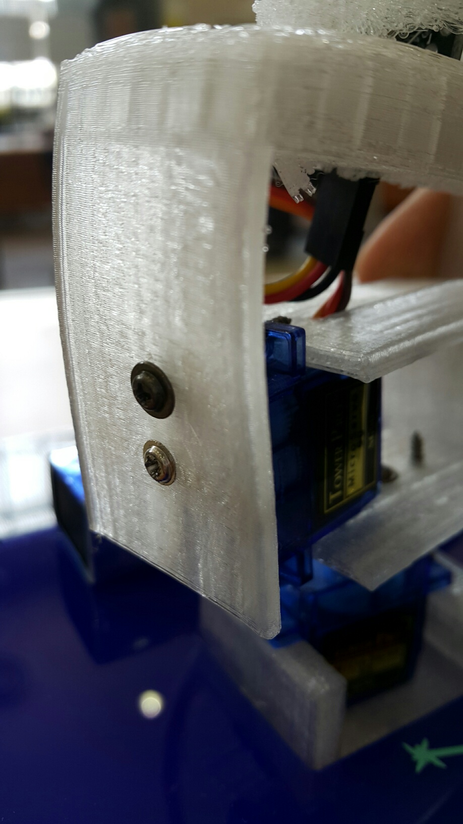
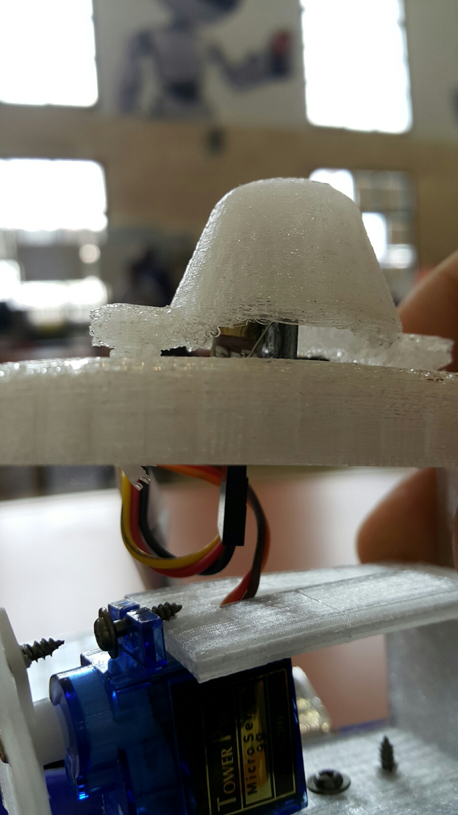
The importance of the 3D printing objects is to connect all the servos together using three parts.
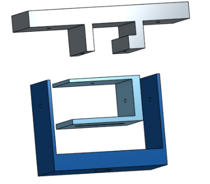
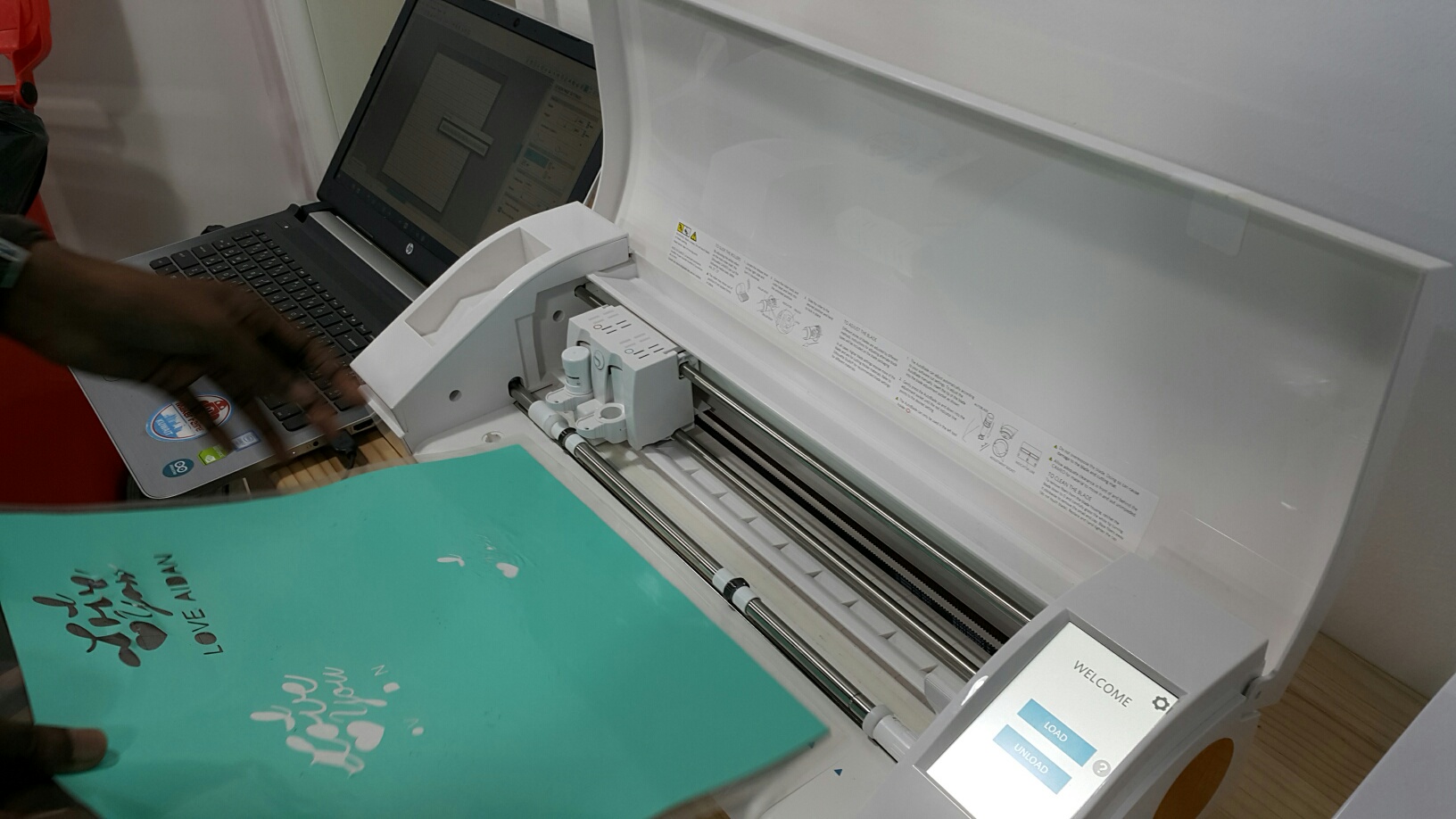
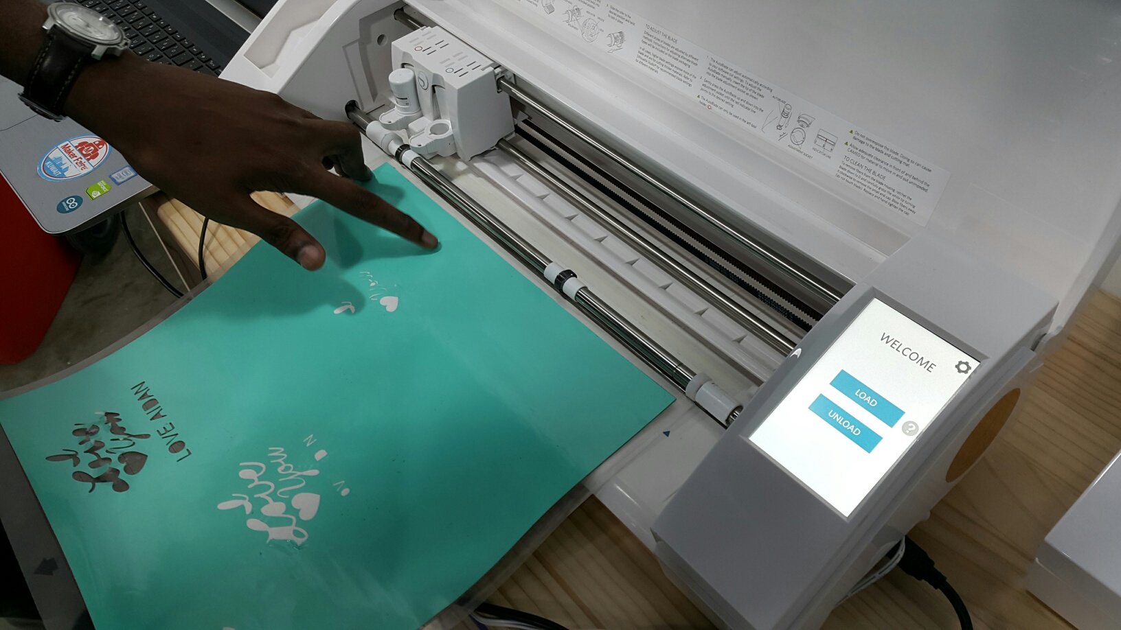
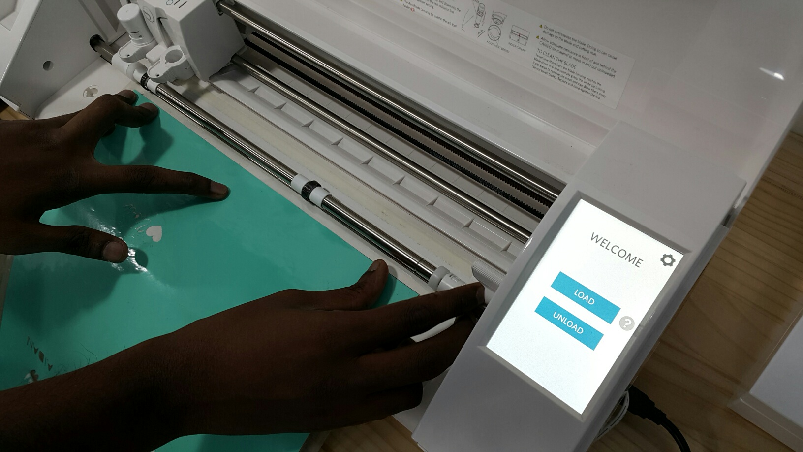
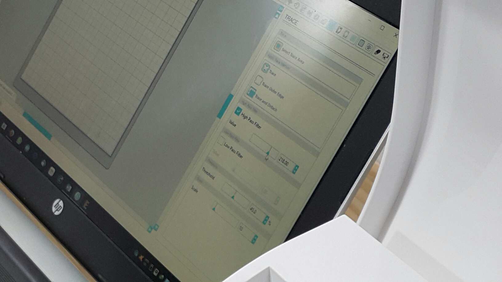
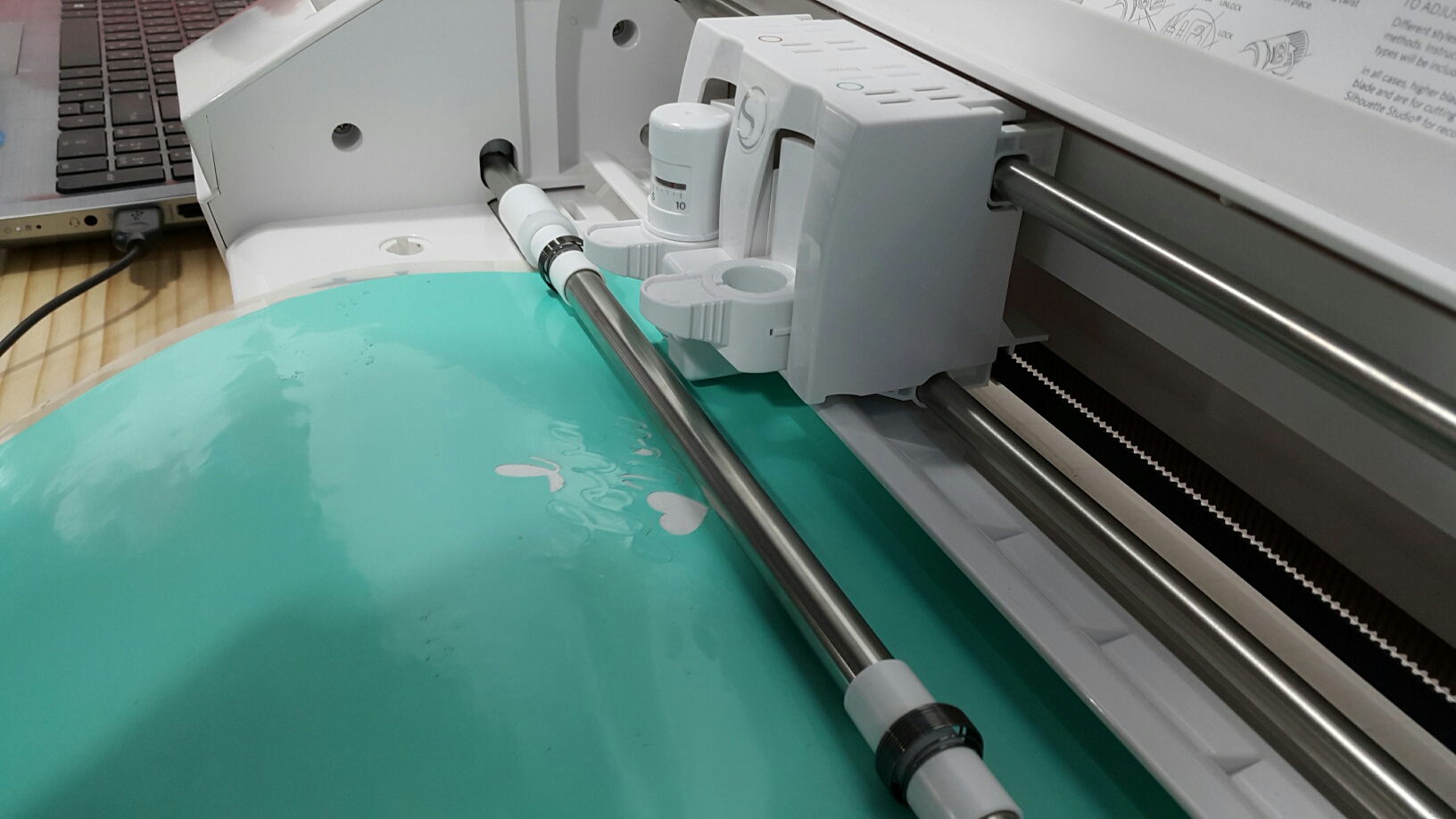
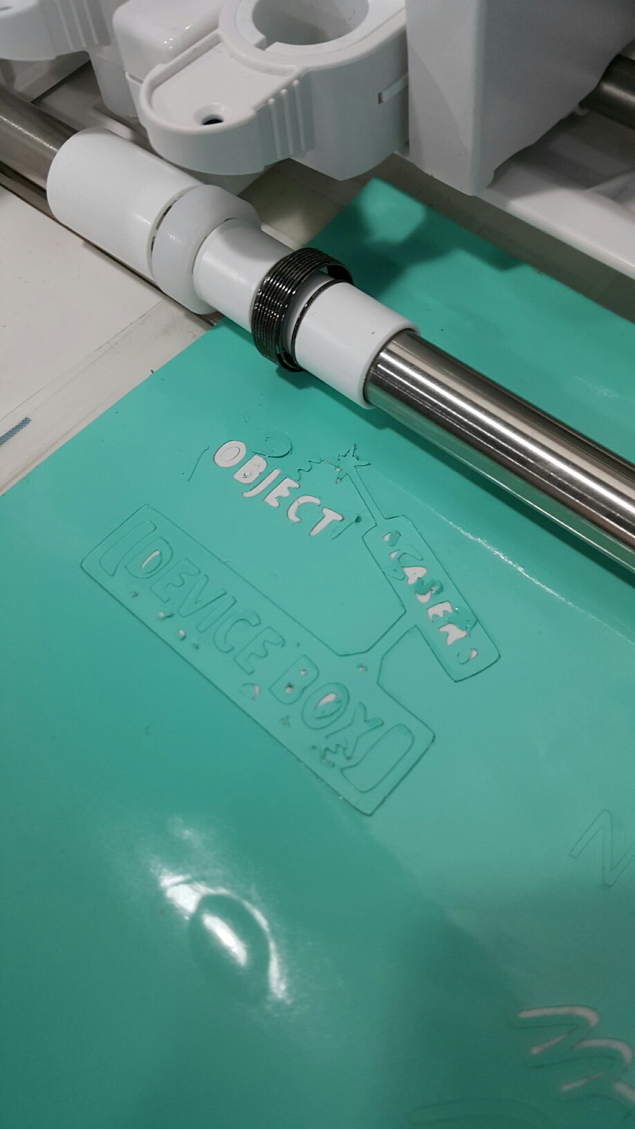
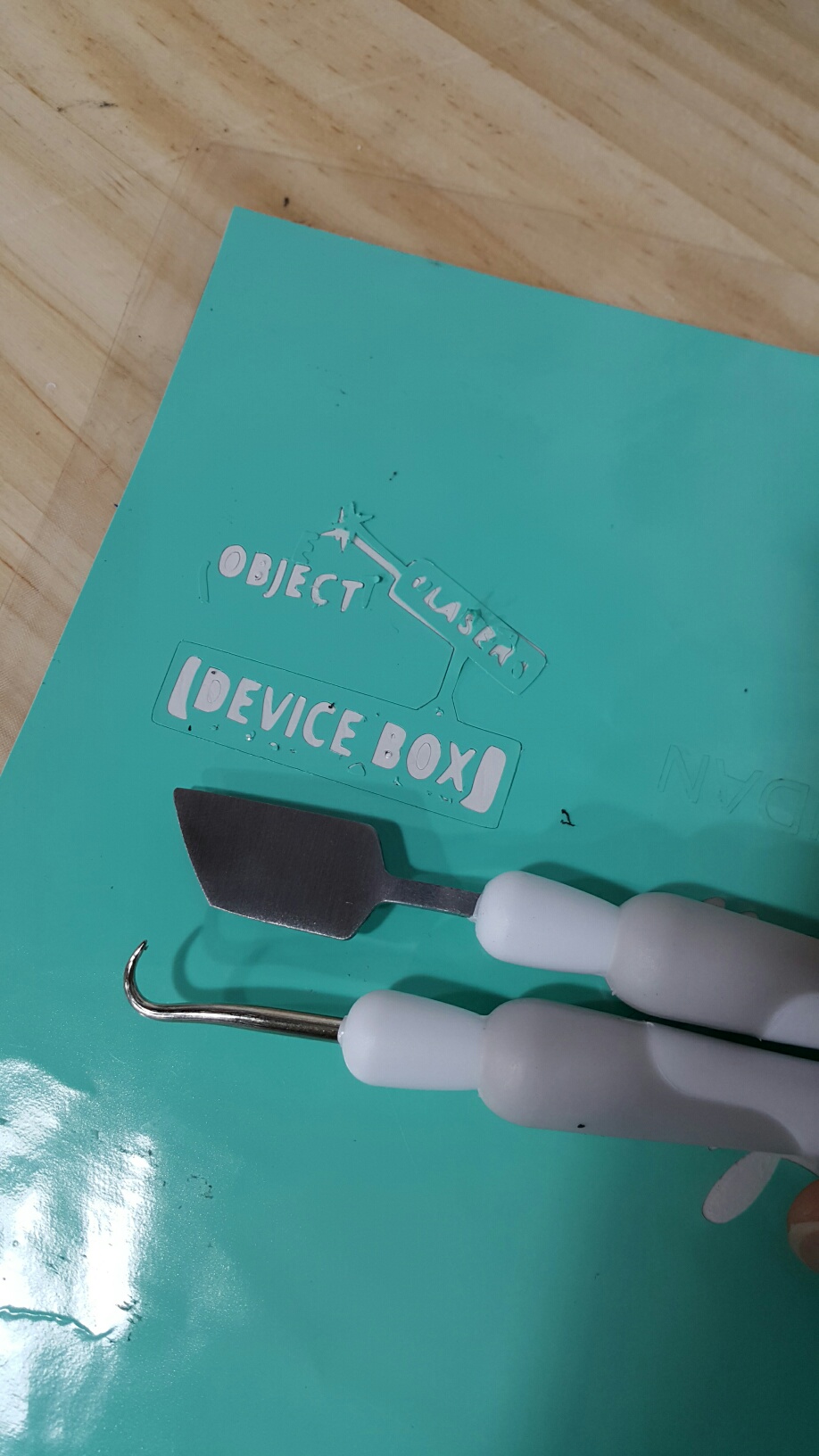
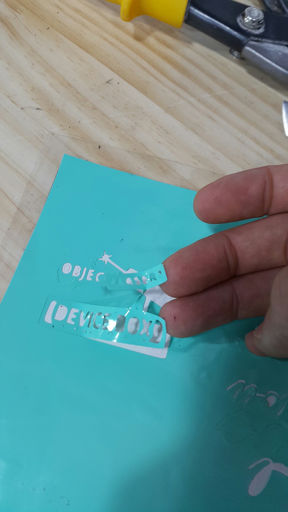

These are the parts that will connect the servos together which will make a rotation of 360 degree movement.


The measurements are made according to the size of the servos. I used small type servos so that the maximum size of the servo holders will not exceed 120mm.


This is the hero shot of this step which is the final 3D printing holders for my project.

Vinyl Design


This will be my vinyl for my final project which will show the purpose of it and it can be the logo at the same time.


The tool I used is the object drawing only, which can be flexible into any shape I want. So i make Squares and Rectangles and combined them together into this laser shape.


First of all, setting the printer and make it prepared for the vinyl cutting.


The sticker should have the transparent support for the printer to cut it smoothly.


Adjusting the bearings to fit the size of the sticker paper so that it can hold it tight.


I need to set the shape with an empty background in order to cut the black shape only.


The printer takes approximately 1 minute to cut the shape I made becuase it is small in size.


Keeping my eyes on the printer so that any problem occures, I can fix it instantly.


As we can see, the shape has been cut nicely and ready to be removed.


I used these removal tools to carefuly remove the sticker due to the size of the design.


Now it is time to put it on the project and see the final view.


It fits nicely. Now people will know more about the device when seeing this laser logo on it.


Assembly


To assemble the project, the servos and the laser need to be hold using the 3D printed holders.

The first servo has been attached using screws.

I have used two screws to hold the servos to avoid loose spin.

The laser is attached without any screws or tapes. It fits the 3D printed holder tight and covered with the 3D printed cover for a better appearance.

Same for the second servo, attached used two screws.

To see the combination, the two servos are now ready to make the half moon movement.

As for the PCB, it is now inside the box attached using double face tape without any problems.

The battery wire is outside the box and the battery is also attached on the box using a strong double face tape. You just connect the wire with the bettery to operate the project.

Future development

For the future development, the project will be more improved and better structured. Rather than only tracking lost items using bluetooth, It will direct the individuals to places. For example, an emergency case, the device will point at the emergency exits or shortcut directions inside building and factories. Also it will direct the people to their cars if they lost the area of the parking lot. The laser will be more powerful or replaced with a safer device which is an LED. And instead of a exposed device, it will be glass closed product for the customers.

The licence for my Project

My project is new to the market and needs a lot of improvement using many points of views. Me, alone, cannot create a huge improvement for my project. So it is important to cooperate with the others to share information and make a continuous development of the project with trade mark exploitation.


Download Files

3D Design
3D part 1
3D part 2
3D part 3
Box (Onshape)
PCB Board
PCB Schematic
Laser Sticker


VIDEO

This is the video of my project with an .MP4 format.
Project Video

Final Project Demonstration