
- This week's lecture : Lecture
- Fab Tutorial Link : Tutorials
- Fab Tools List : Tools List
Assignment:
- Add an output device to a microcontroller board you've designed and program it to do something
What I did this week?
- Developed a general purpose board and an LED display board(using charlieplex).
- Documented the design and fabrication process.
- Identified relevant informations from microcontroller datasheet.
- Programmed the chip using fabISP developed in Electronic Production week.
- Outlined problems and how I fixed them.
- Uploaded design files and codes.
This week we were taught about various output devices. We have already learned about PCB board designing and Embedded Programming in previous weeks. Now its time to add an output device to our board and program it. Prof.Neil introduced us to various output devices available for experimenting. Various devices and sample codes are available in tools page link above.
I liked multiplexing of LED arrays. Its interesting that lots of LEDs can be controlled by using low number of microcontroller pins. I decided to give it a try. So, I am planning to build a LED display board which can be used as plug and play module. I am also building a general purpose board to drive this LED display, using ATTiny44 chip. So, total two boards!
Getting Started
Charlieplexing is a technique for driving a multiplexed display in which relatively few I/O pins on a microcontroller are used to drive an array of LEDs. Charlieplexing is named after Charles Allen at Maxim who developed the technique.
Here is a rough diagram of multiplexing 6 LEDs using 3 pins from microcontroller.
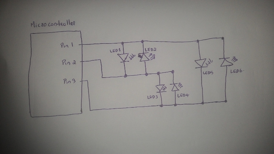
I am designing a display board with 15 LEDs. To calculate number of LEDs which can be controlled using N microcontroller pins, we have the formula N(N-1). So, using 5 pin we can control 20 LEDs. Using 4 pins, we can control 12 LEDs. Since I need 15 LEDs, I have to use minimum 5 pins from microcontrolled. There is enough pins available in ATTiny44 chip!
For general purpose board, I am planning to add a switch by which I can trigger particular action. And I will connect all possible other pins to a series of header pins.
Designing
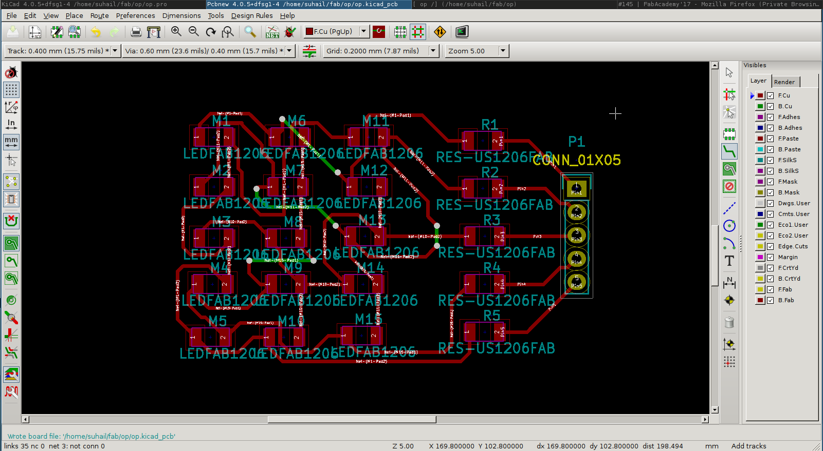
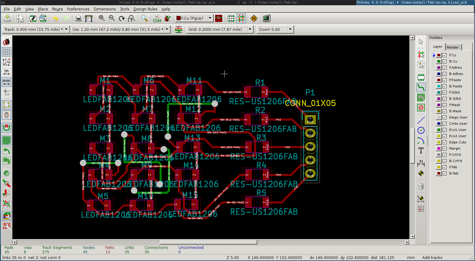
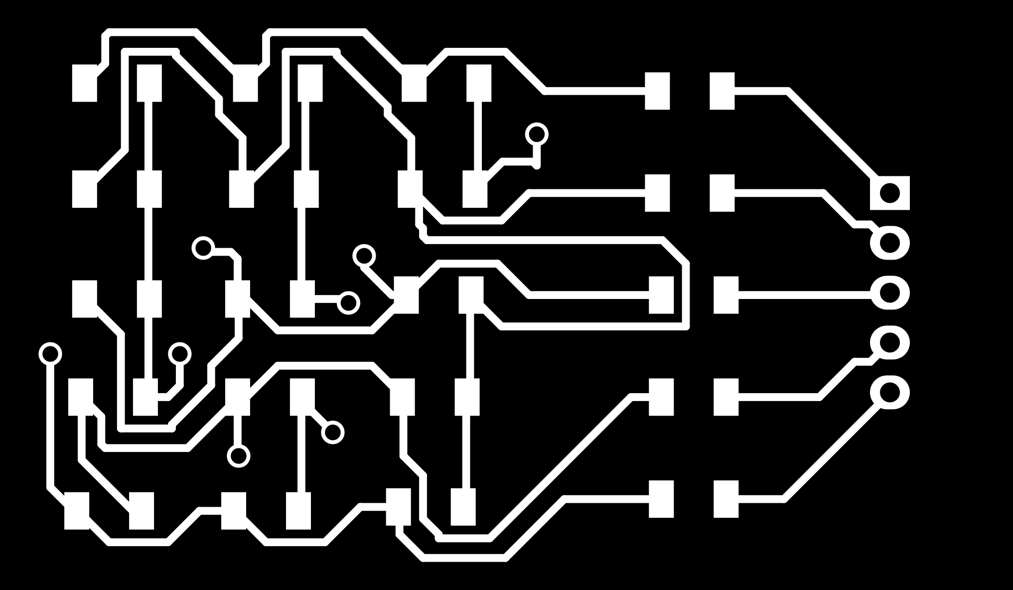
I designed the circuit using KiCad software. I started with LED display module first. I created 5 rows of LEDs with each row containing 3 LEDs. And connected these LED array int0 5 pins through a resistor. Schematic diagram and circuit board design are available below.
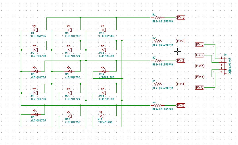
(There is a mistake in above design image. I have explained it below). I calculated the resistor value as below. I was using Orange LED (refer digikey.com: 160-1403-1-ND for rating details).
R = (V - VL)/IL
Where V = 5V,
VL (LED voltage rating) = 2V,
IL (LED current rating) = 20mA,
therefore R = 100 Ohm
According to design, when a particular LED is ON by passing 1 & 0 through corresponding pins, current should pass through two resistors every time. So, I am using resistor of 49.9 Ohm here.
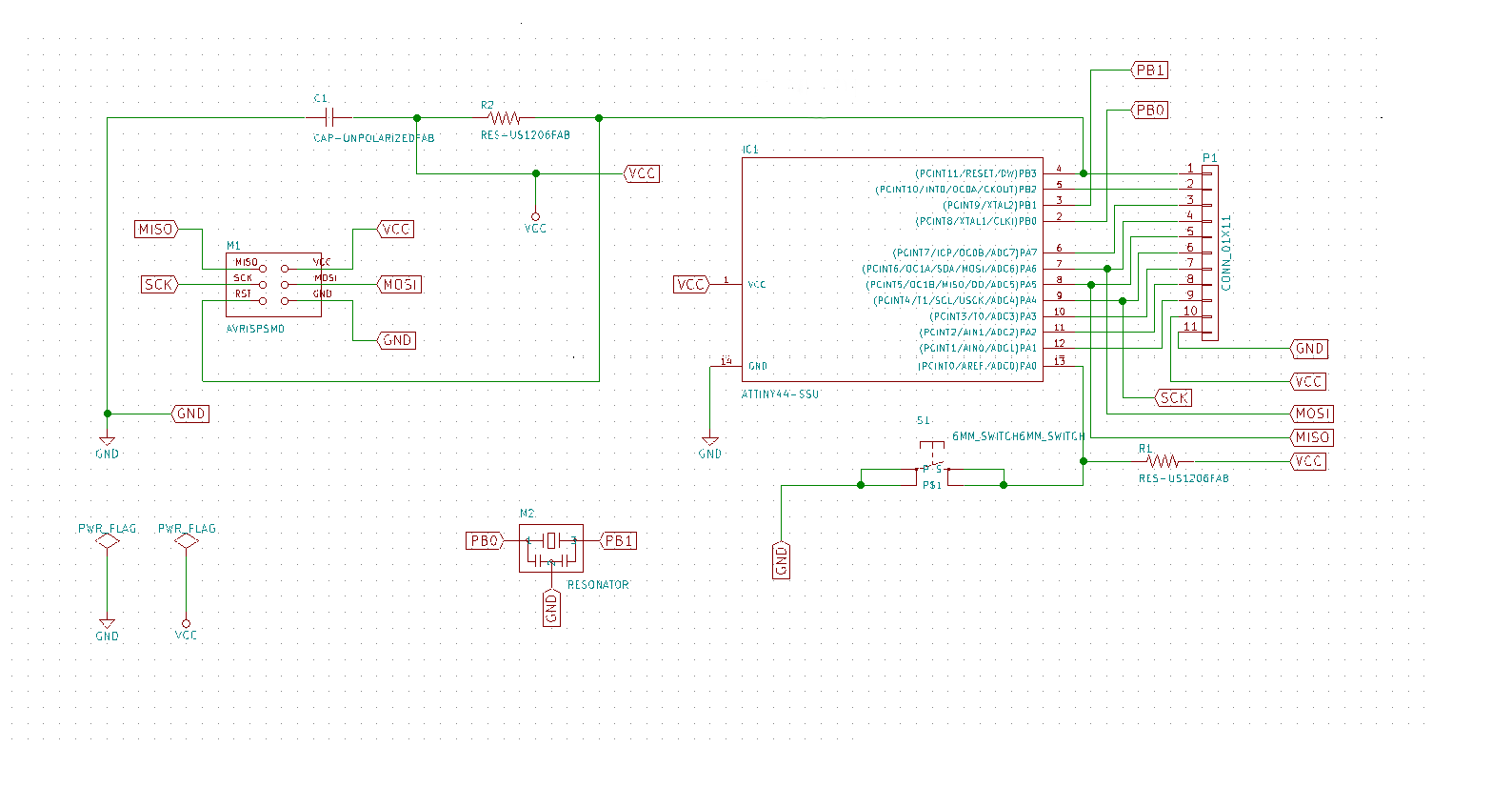
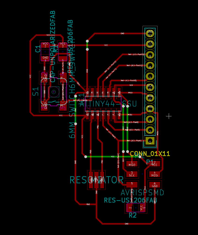
Then I designed the general purpose board. It contains a switch, 20MHz resonator and many header pins for connecting devices. Here is the schematic and design images.
Milling and Cutting
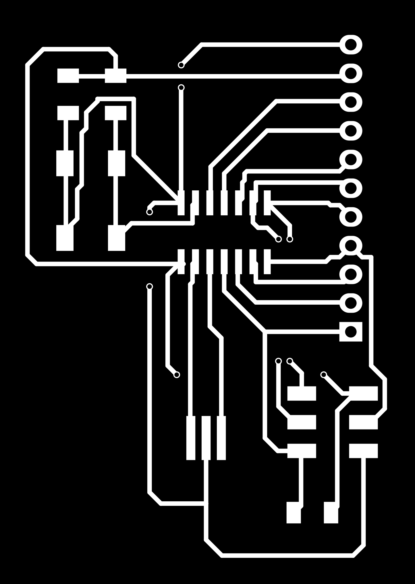
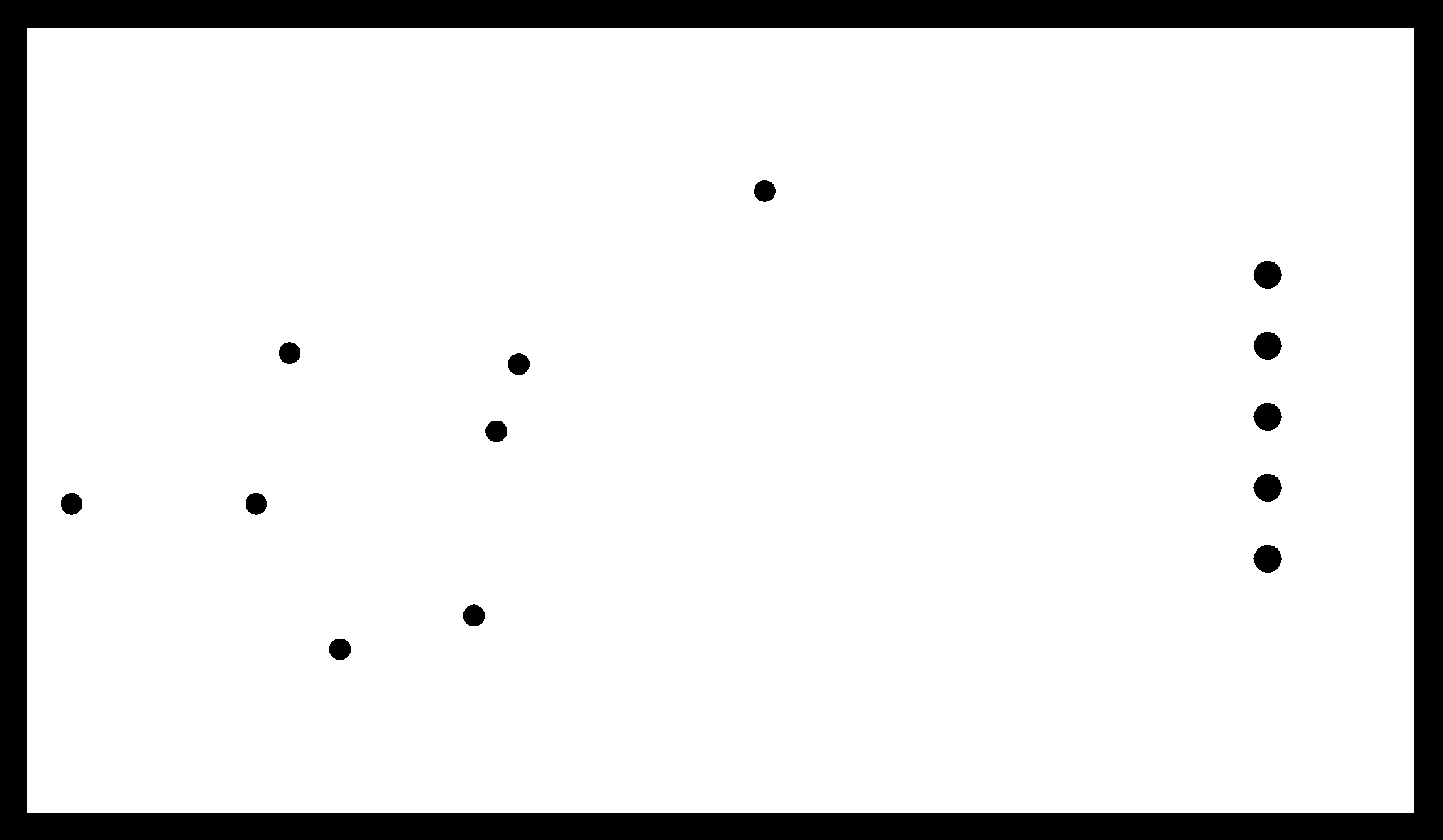
I exported svg file from kicad and created necessary files to feed into modella machine. Below are milling and cutout images for LED display board.
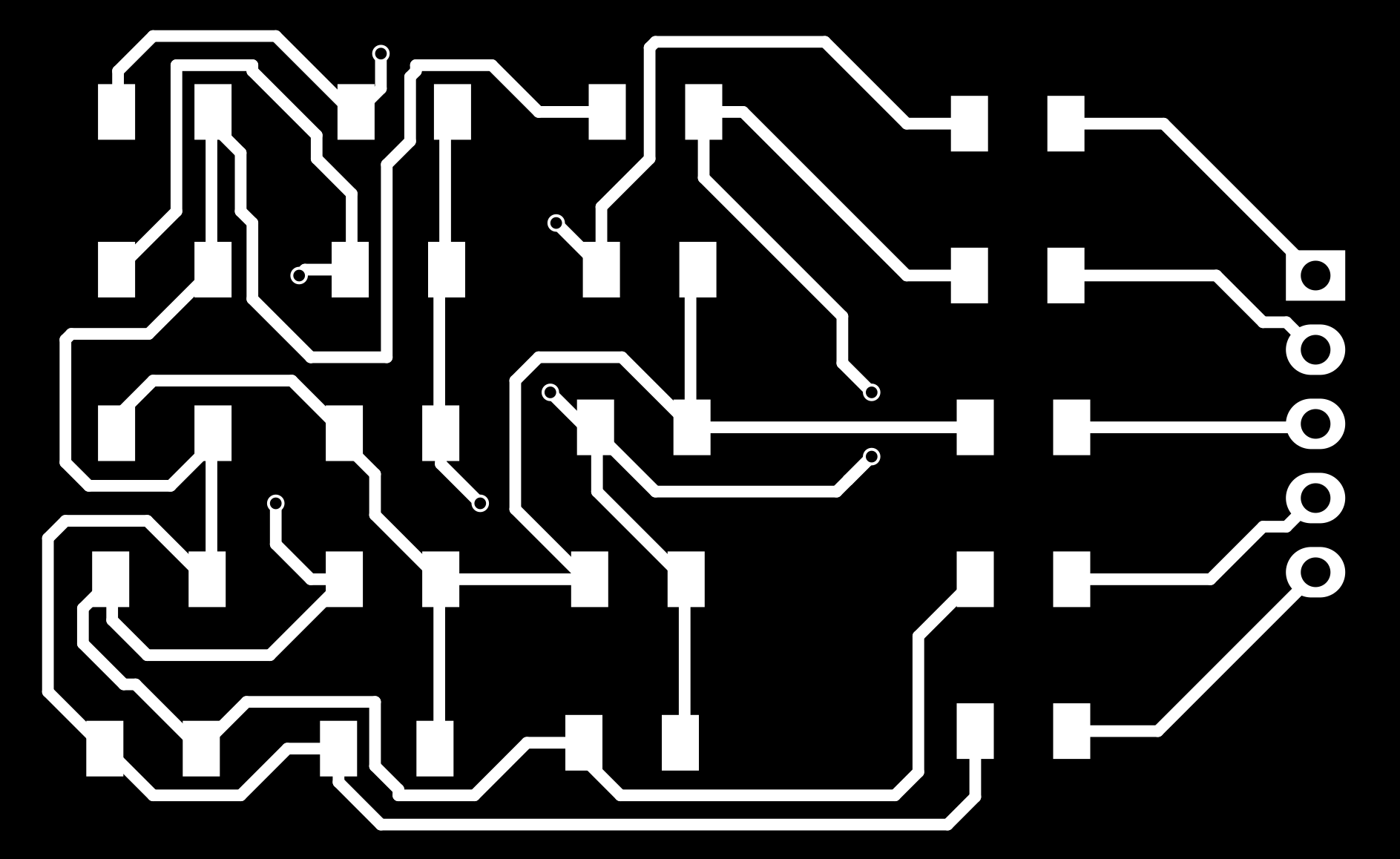

Milling and cutout images for general purpose board are below.

Oops...!!!
Only after cutting two PCBs I realised that I had made some mistakes in LED display board. If you check that schematic and design images, you can see that, first pin in schematic is connected to 3rd LED in first row. But in PCB design, second pin is connected to the same LED. I was confused initially. But then my instructor Sibu said that the issue is related to annotation. What happened is, I had edited schematic annotation after I started working on the design part. I had continued the design without rebuilding the board.
I corrected this by using 'rebuild' option under 'read current netlist' in PCB design window. I had to remove most of the routes and rerouted them accordingly. Now its okay.
Next issue is, I have to use jumber wires in green colored track. But I had forgot to add these holes in cutout board. For general purpose board I used driller to create holes manually. But I had lost some tracks and soldering became very difficult. My board doesn't look clean now. I checked continuity using multimeter and its okay. So I decided to use the same board. But for the new corrected LED display board, I added the holes in cutout file.
New files for LED display board are here.
Design file
Milling board
Cutout board
Mapping LEDs
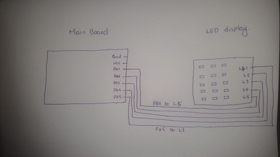
I referred datasheet to understand pinout and PORTS for ATTiny44. I connected the LED board as per image below. Top pin from LED board is connected to PA1 of general purpose board, 2nd pin to PA2 etc and 5th pin to PA5. So, I have connected the display to PORTA of main board. Then I created a table to note pin to which HIGH and LOW are to be fed for making the LED ON. Here is the table.
Remember, this is how my connection looks like;
| LED 1 L1-High L5-Low PORTA - 1<<PA5 | LED 6 L1 - High L4 - Low PORTA - 1<<PA5 | LED 11 L1 - High L3 - Low PORTA - 1<<PA5 |
| LED 2 L2 - High L5 - Low PORTA - 1<<PA4 | LED 7 L2 - High L4 - Low PORTA - 1<<PA4 | LED 12 L2 - High L3 - Low PORTA - 1<<PA4 |
| LED 3 L3 - High L5 - Low PORTA - 1<<PA3 | LED 8 L3 - High L4 - Low PORTA - 1<<PA3 | LED 13 L3 - High L2 - Low PORTA - 1<<PA3 |
| LED 4 L4 - High L5 - Low PORTA - 1<<PA2 | LED 9 L4 - High L3 - Low PORTA - 1<<PA2 | LED 14 L4 - High L2 - Low PORTA - 1<<PA2 |
| LED 5 L5 - High L4 - Low PORTA - 1<<PA1 | LED 10 L5 - High L3 - Low PORTA - 1<<PA1 | LED 15 L5 - High L2 - Low PORTA - 1<<PA1 |
For example: According to above data, to make LED1 ON, use the following data
- L1 is High, so PA5 is High (L1 connected to PA5).
- L5 is Low, so PA1 is Low.
- Therefore DDRA = 0b00100010 and PORTA = 0b00100000 (1<<PA5).
Programming the board
All that I have left to do is programming. I want to count numbers from 0 to 9 using LED display. Before writing the program, I tried to '0' only and then '1' only. All codes are available below.
1. Program to display '1' in LED display
Code:
/*
Author: Suhail P
FabAcademy 2017 - #145
FABLAB Kochi

This code is used to display number '1'
in LED display. Display contains 15
LEDs(3x5).

PORT connections:
- PA5 to first row of LED board
- PA4 to second row of LED board
- PA3 to third row of LED board
- PA2 to fourth row of LED board
- PA1 to fifth row of LED board
*/

#include<avr/io.h>
#define F_CPU 20000000
#include<util/delay.h>
#define DELAY_TIME 0.1

int main(void) {
  int i;
  /*
  RGSTR[] This array stores DDRx values corresponding to
  all LED combinations
  */
  char RGSTR[] = {
    0b00000110, //DDRx- pin 1 and 2
    0b00001010, //DDRx- pin 1 and 3
    0b00010010, //DDRx- pin 1 and 4
    0b00100010, //DDRx- pin 1 and 5
    0b00001100, //DDRx- pin 2 and 3
    0b00010100, //DDRx- pin 2 and 4
    0b00100100, //DDRx- pin 2 and 5
    0b00011000, //DDRx- pin 3 and 4
    0b00101000, //DDRx- pin 3 and 5
  };

  /*
  leds[] array contains {DDRx,PORTx} value combinations
  for making LED ON
  */
  char leds[15][2] = {
    //column 1 LEDs
    {3,0b00100000},
    {2,0b00010000},
    {1,0b00001000},
    {0,0b00000100},
    {0,0b00000010},
    //column 2 LEDs
    {6,0b00100000},
    {5,0b00010000},
    {4,0b00001000},
    {4,0b00000100},
    {1,0b00000010},
    //column 3 LEDs
    {8,0b00100000},
    {7,0b00010000},
    {7,0b00001000},
    {5,0b00000100},
    {2,0b00000010},
  };

  // infinite loop
  while(1) {
    //LEDs to ON - 5,6,7,8,9
    for (i=5;i<10;i++){
          //set DDRA for current pins
          DDRA = RGSTR[leds[i][0]];
          //LED ON
          PORTA = leds[i][1];
          _delay_ms(DELAY_TIME);
          //LED OFF
          PORTA = 0b00000000;
          _delay_ms(DELAY_TIME);
    }
  }
}
compiling and flashing:
$ avr-gcc -g -Os -mmcu=attiny44a -c one.c
$ avr-gcc -g -mmcu=attiny44a -o one.elf one.o
$ avr-objcopy -j .text -j .data -O ihex one.elf one.hex
$ sudo avrdude -c usbtiny -p t44 -U flash:w:one.hex
Output:
2. Program to display '0'(zero) in LED display
Code:
    /*
    Author: Suhail P
    FabAcademy 2017 - #145
    FABLAB Kochi

    This code is used to display number '0'
    in LED display. Display contains 15
    LEDs(3x5).

    PORT connections:
    - PA5 to first row of LED board
    - PA4 to second row of LED board
    - PA3 to third row of LED board
    - PA2 to fourth row of LED board
    - PA1 to fifth row of LED board
    */

    #include<avr/io.h>
    #define F_CPU 20000000
    #include<util/delay.h>
    #define DELAY_TIME 0.025

    int main(void) {
    int i;
    int j;
    char RGSTR[] = {
      0b00000110, //DDR- pin 1 and 2
      0b00001010, //DDR- pin 1 and 3
      0b00010010, //DDR- pin 1 and 4
      0b00100010, //DDR- pin 1 and 5
      0b00001100, //DDR- pin 2 and 3
      0b00010100, //DDR- pin 2 and 4
      0b00100100, //DDR- pin 2 and 5
      0b00011000, //DDR- pin 3 and 4
      0b00101000, //DDR- pin 3 and 5
    };

    char leds[15][2] = {
      //column 1 LEDs
      {3,0b00100000},
      {2,0b00010000},
      {1,0b00001000},
      {0,0b00000100},
      {0,0b00000010},
      //column 2 LEDs
      {6,0b00100000},
      {5,0b00010000},
      {4,0b00001000},
      {4,0b00000100},
      {1,0b00000010},
      //column 3 LEDs
      {8,0b00100000},
      {7,0b00010000},
      {7,0b00001000},
      {5,0b00000100},
      {2,0b00000010},
    };

char numbers[11][14] = {
      {0,5,10,11,12,13,14,9,4,3,2,1},  //LED sequence for number 0
      {10,11,12,13,14},                            //number 1
      {0,5,10,11,12,7,2,3,4,9,14},     //number 2
      {0,5,10,11,12,7,2,13,14,9,4},        //number 3
      {0,1,2,7,12,13,14},                          //number 4
      {10,5,0,1,2,7,12,13,14,9,4},     //number 5
      {10,5,0,1,2,3,4,9,14,13,12,7},       //number 6
      {0,5,10,11,12,13,14},                        //number 7
      {0,5,10,11,12,13,14,9,4,3,2,7},      //number 8
      {14,13,12,11,10,5,0,1,2,7},          //number 9
    };
// infinite loop
while(1) {
      for (j=0;j<=12;j++) {
        DDRA = RGSTR[leds[numbers[0][j]][0]];
    PORTA = leds[numbers[0][j]][1];
        _delay_ms(DELAY_TIME);
        PORTA = 0b00000000;
        _delay_ms(DELAY_TIME);
        }
      }
    }
compiling and flashing:
$ avr-gcc -g -Os -mmcu=attiny44a -c zero.c
$ avr-gcc -g -mmcu=attiny44a -o zero.elf zero.o
$ avr-objcopy -j .text -j .data -O ihex zero.elf zero.hex
$ sudo avrdude -c usbtiny -p t44 -U flash:w:zero.hex
Output:
3. Program to count from 0 to 9 in LED display
Code:
    /*
    Author: Suhail P
    FabAcademy 2017 - #145
    FABLAB Kochi

    This code is used to count numbers from
    0 to 9 in LED display. Display contains 15
    LEDs(3x5).

    PORT connections:
    - PA5 to first row of LED board
    - PA4 to second row of LED board
    - PA3 to third row of LED board
    - PA2 to fourth row of LED board
    - PA1 to fifth row of LED board
    */

    #include<avr/io.h>
    #define F_CPU 20000000
    #include<util/delay.h>
    #define DELAY_TIME 0.02

    int main(void) {
      int i,j,count;
      /*
      RGSTR[] This array stores DDRx values corresponding to
  all LED combinations
      */
      char RGSTR[] = {
      0b00000110, //DDRx- pin 1 and 2
      0b00001010, //DDRx- pin 1 and 3
      0b00010010, //DDRx- pin 1 and 4
      0b00100010, //DDRx- pin 1 and 5
      0b00001100, //DDRx- pin 2 and 3
      0b00010100, //DDRx- pin 2 and 4
      0b00100100, //DDRx- pin 2 and 5
      0b00011000, //DDRx- pin 3 and 4
      0b00101000, //DDRx- pin 3 and 5
    };
    /*
leds[] array contains {DDRx,PORTx} value combinations
for making LED ON
*/
char leds[15][2] = {
      //column 1 LEDs
      {3,0b00100000},
      {2,0b00010000},
      {1,0b00001000},
      {0,0b00000100},
      {0,0b00000010},
      //column 2 LEDs
      {6,0b00100000},
      {5,0b00010000},
      {4,0b00001000},
      {4,0b00000100},
      {1,0b00000010},
      //column 3 LEDs
      {8,0b00100000},
      {7,0b00010000},
      {7,0b00001000},
      {5,0b00000100},
      {2,0b00000010},
    };

    /*
LED sequence for each number from 0 to 9
*/
char numbers[10][14] = {
      {0,5,10,11,12,13,14,9,4,3,2,1}, //LED sequence for number 0
      {0,1,2,3,4},                 //LED sequence for number 1
      {0,5,10,11,12,7,2,3,4,9,14}, //LED sequence for number 2
      {0,5,10,11,12,7,2,13,14,9,4},        //LED sequence for number 3
      {0,1,2,7,12,13,14},          //LED sequence for number 4
      {10,5,0,1,2,7,12,13,14,9,4}, //LED sequence for number 5
      {10,5,0,1,2,3,4,9,14,13,12,7},       //LED sequence for number 6
      {0,5,10,11,12,13,14},                //LED sequence for number 7
      {0,5,10,11,12,13,14,9,4,3,2,1,7},//LED sequence for number 8
      {14,13,12,11,10,5,0,1,2,7},  //LED sequence for number 9
    };
// infinite loop
while(1) {
      //Loop for displaying 0 to 9
      for (i=0;i<10;i++){
        //Each number stays until this loop
            for (count=0;count<100;count++) {
              //LED combination corresponding to current number
              for (j=0;j<(sizeof(numbers[i]));j++) {
                DDRA = RGSTR[leds[numbers[i][j]][0]];
                    PORTA = leds[numbers[i][j]][1];
                    _delay_ms(DELAY_TIME);
                    PORTA = 0b00000000;
                    _delay_ms(DELAY_TIME);
                    }
              }
            }
      }
    }
compiling and flashing:
$ avr-gcc -g -Os -mmcu=attiny44a -c counter.c
$ avr-gcc -g -mmcu=attiny44a -o counter.elf counter.o
$ avr-objcopy -j .text -j .data -O ihex counter.elf counter.hex
$ sudo avrdude -c usbtiny -p t44 -U flash:w:counter.hex
Output: