- This week's lecture : Lecture
- Fab Tutorial Link : Tutorials
- Fab Tool's List : Tools List
This week Prof. Neil talked about PCB milling, soldering components etc and he want us to build an ISP board and program it, which we will be using in coming days. There are various Fab-ISP designs available and I decided to try Brian's Design.
What I did this week?
- Learned the process of milling, stuffing, de-bugging and programming
- Documented how I made and programmed the ISP board.
- Documented problems I faced and how I fixed them.
- Included a 'hero shot' of my board (available at the bottom of this page).
Assignment:
- Make an in-circuit programmer by milling the PCB, then optionally trying other processes
Fab-ISP
In-system programming (ISP), also called In-Circuit Serial Programming (ICSP), is the ability of some programmable logic devices, microcontrollers, and other embedded devices to be programmed while installed in a complete system, rather than requiring the chip to be programmed prior to installing it into the system. --wikipedia--
Fab-ISP is an in-system programmer for AVR microcontrollers, which can be developed with in a fablab. This allows us to program microcontrollers on other boards using a 6 pin IDC cable. Programming is done through avrdude. We are using ATtiny45 chip in this ISP.
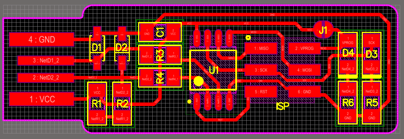
ISP PCB design:
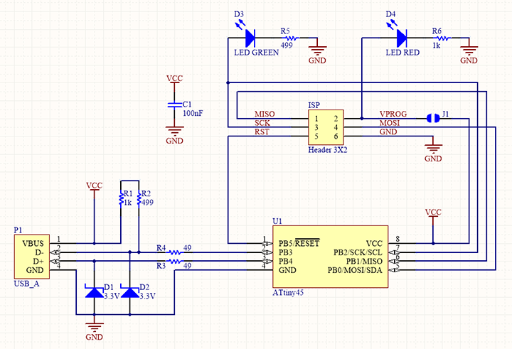
ISP Schematic:
Traces image:
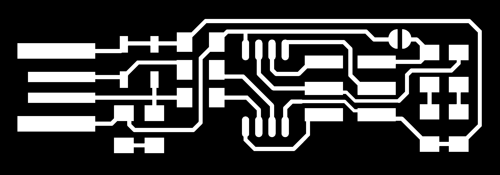
Cutout image:

Images source: Brian's Design.
ATtiny45
These are small, cheap microcontrollers that are convenient for running simple programs. The ATtiny45 has eight legs with 6 general purpose I/O lines and 4KB of flash memory. Here is a pinout diagram of ATtiny45/85 chip (source: highlowtech.org).
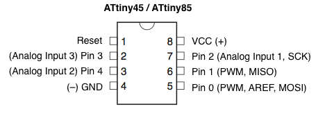
Note that, we can use the reset pin as another IO pin if we disable the reset pin, then we wont be able to program this chip again, unless the chip is fed with high voltage. We will disable this pin in the end.
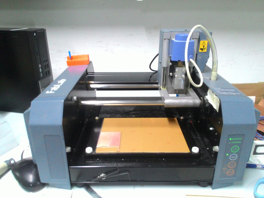
Roland Modella 3D plotter
Roland Modella MDX-20 is a desktop CNC machine used for making PCBs, carving moulds with soft materials like wax and can also be used for scanning 3D models of objects. The detachable base plate moves along Y axis, the header where the driller is mounted moves along X axis and the carriage where the motor is attached moves along the Z axis.
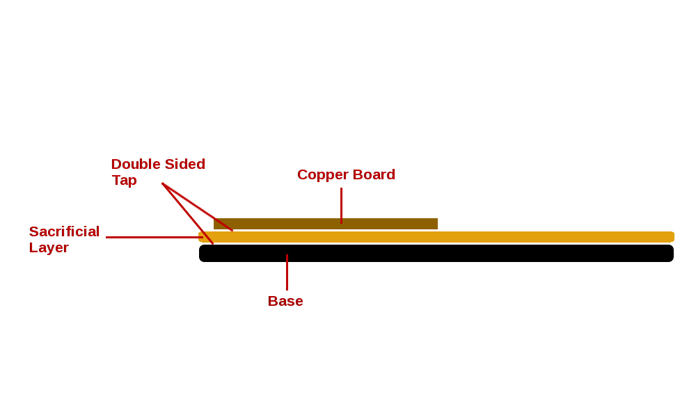
Setting Up
The base of the machine, which moves along the Y axis, contains a detachable metallic plate where we place our PCB. But inorder to protect out drill bits, we have to provide a sacrificial layer above the base metal plate. We place our PCB above this sacrificial layer. A copper board with copper side faced down is used as sacrificial layer.
Milling and cutting
We have to do the milling first. For this, drill bit of size 1/64 is used. I did the following steps
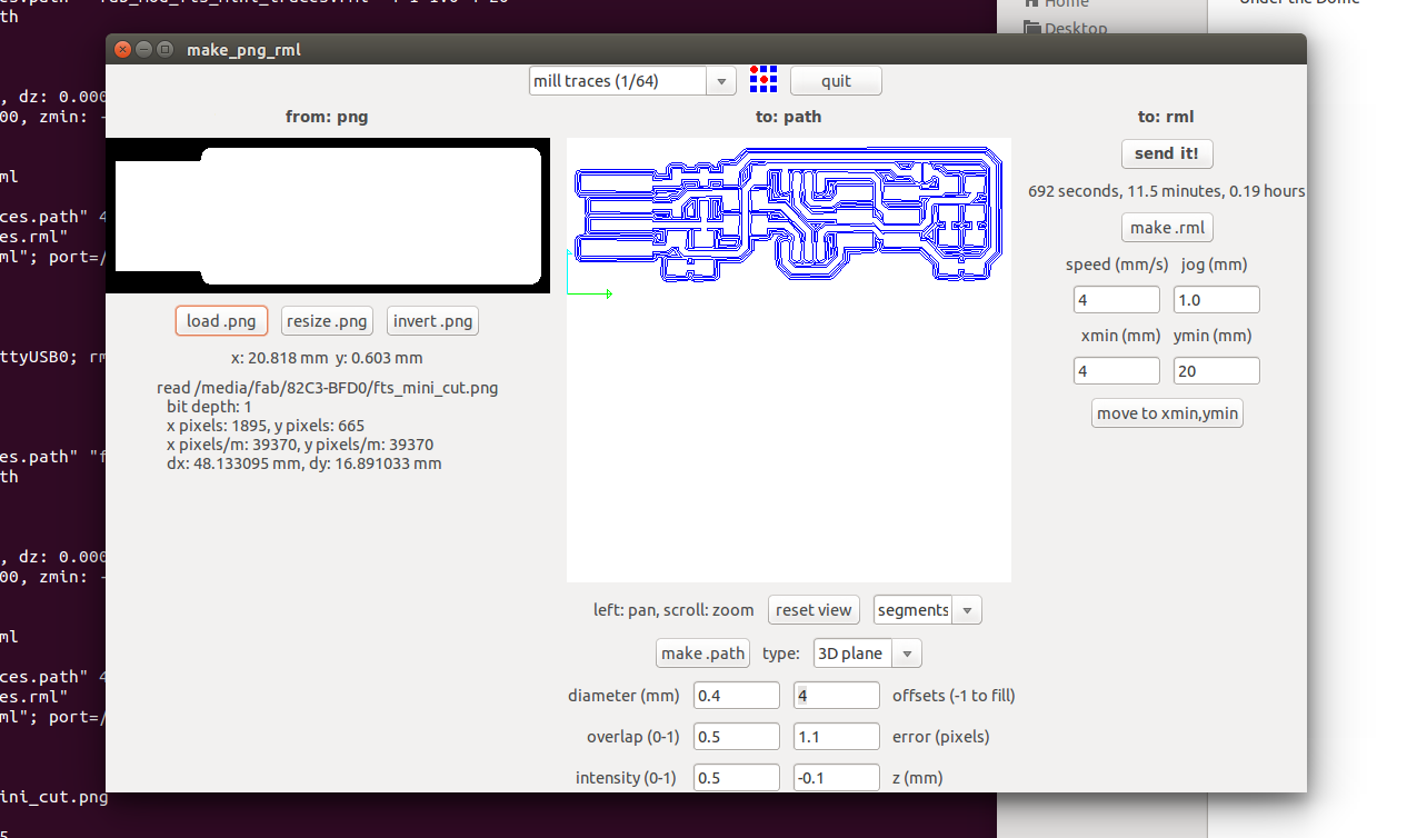
Select 'View' from modella menu so that the driller reach the corner point of the board. Open fab module using command fab and select 'png' in 'input format' section and 'Roland MDX-20 mill' in 'output process' select box.
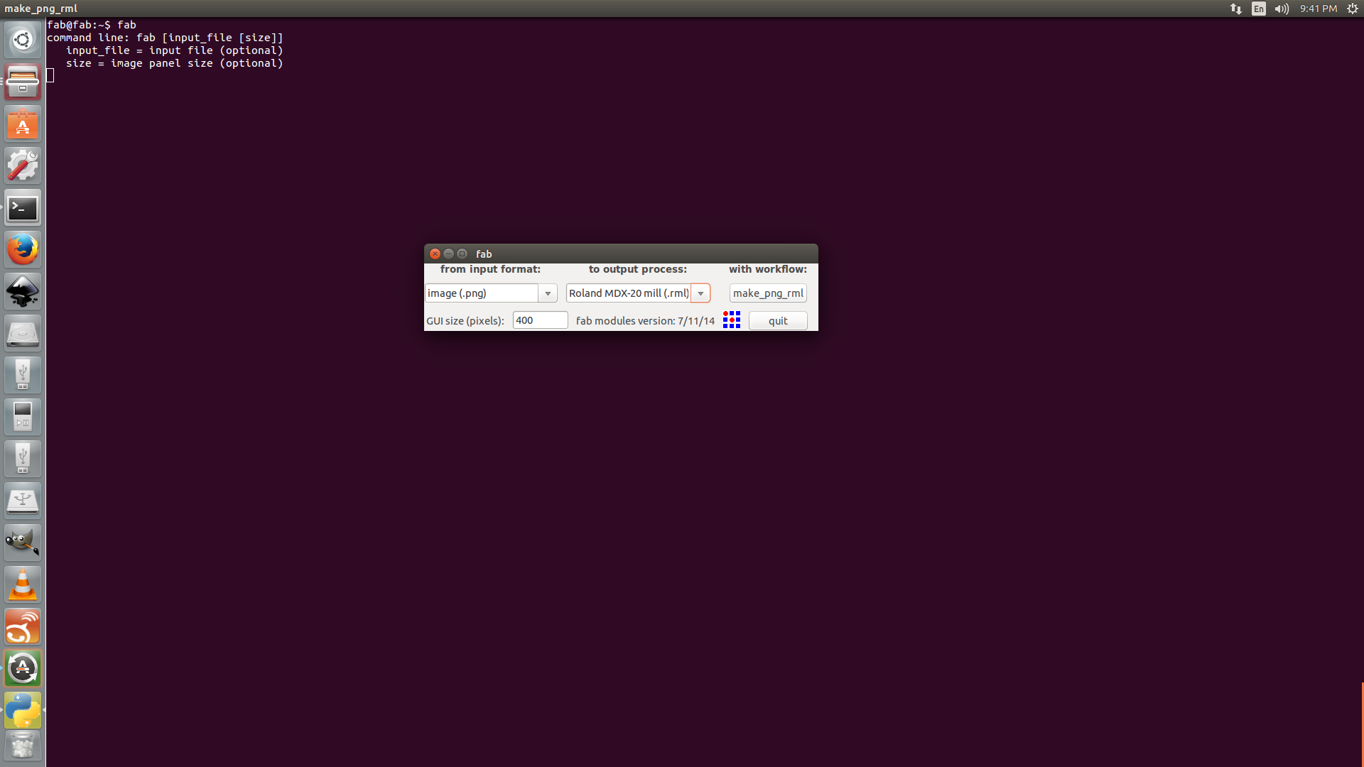
Load mill-image to the software and click on Make Path button to draw paths. Adjust X and Y positions of driller using Xmin and Ymin options on the right side. To move the head along Z axis, use Up & Down buttons on the Modella machine.
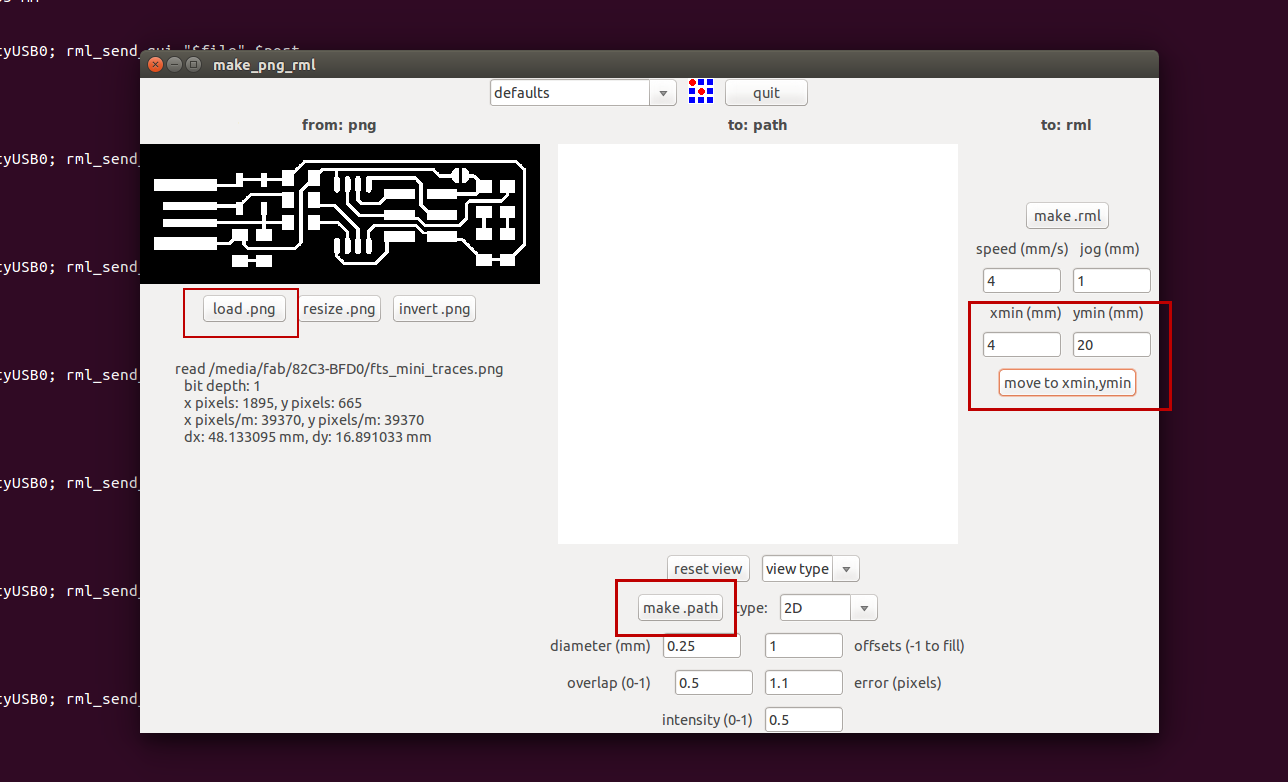
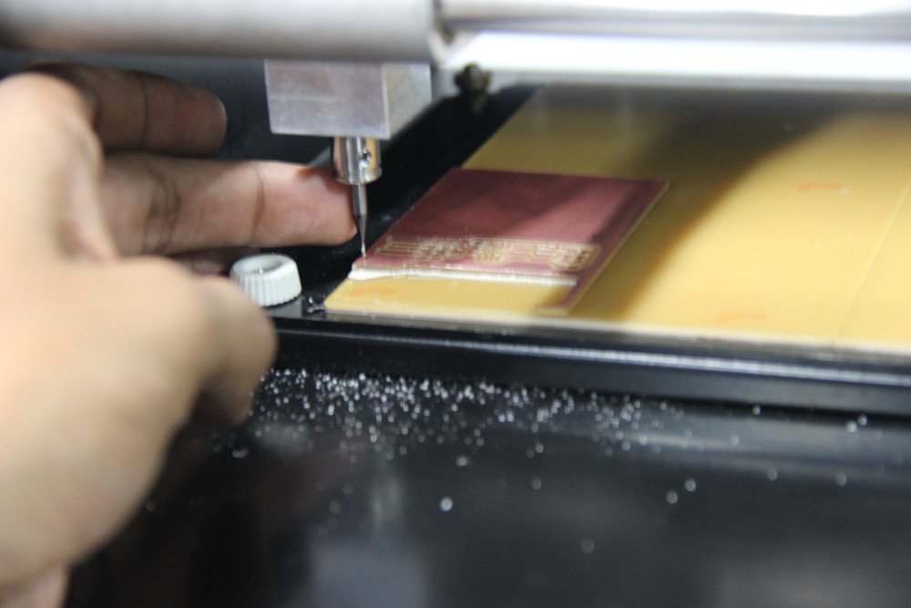
Now adjust the bit such that it touches the board and tighten the screw using allen key. Select mill bit size as 1/64 from select box.
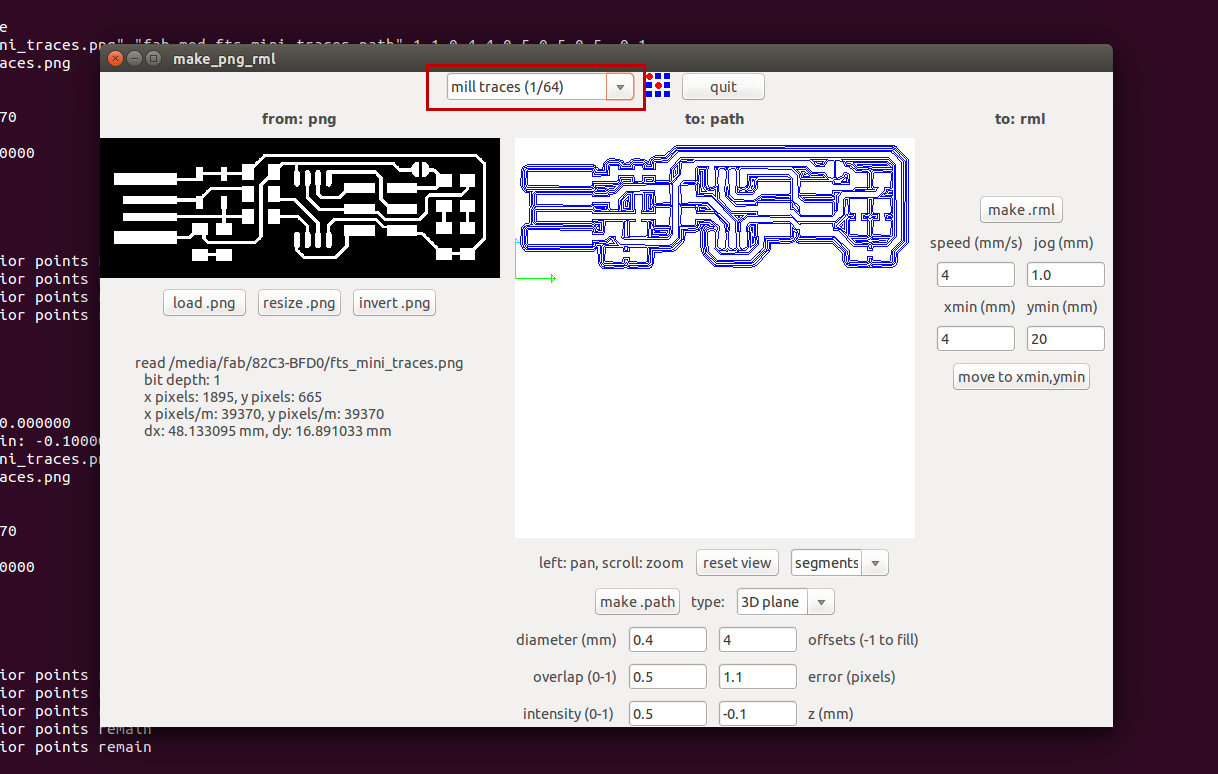
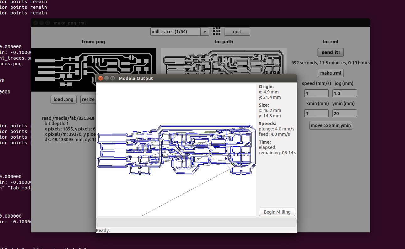
Now click on make .rml button and then send it button, then click on Begin Milling on the new window opened. Then the machine will start the milling. The machine will remove black region and preserve the white region.
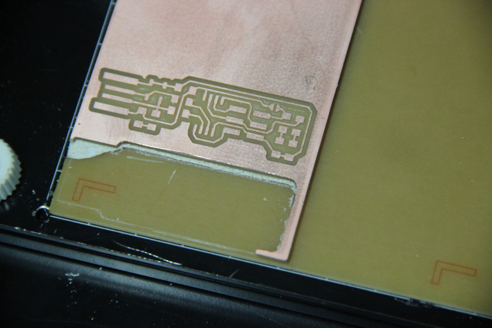
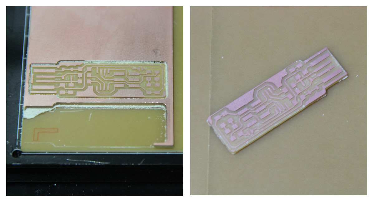
Here is a photo taken after milling.
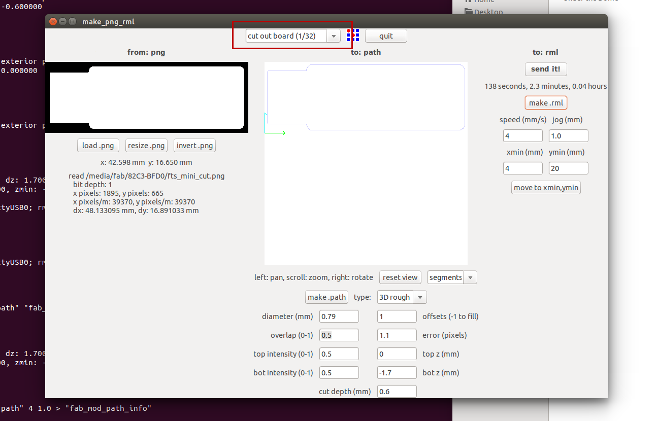
Now we have to do the cutting. Same steps are followed, but using another bit of size 1/32.
Move the header up using Up button on modella machine menu. Bring the bit to initial point like we did previously and change the bit to size 1/32. Then bring the header down using Down button, so that there is some distance between the bit and the copper plate. Now adjust the bit such that it touches the board and tighten the screw using allen key.
Load the new image for cutting the board.
Choose cut out board(1/32) from select box. Then click on Make Path, then Make .rml and then send it button respectively.
Here is a photo taken after cutting.
Here is a gif image of milling and cutting
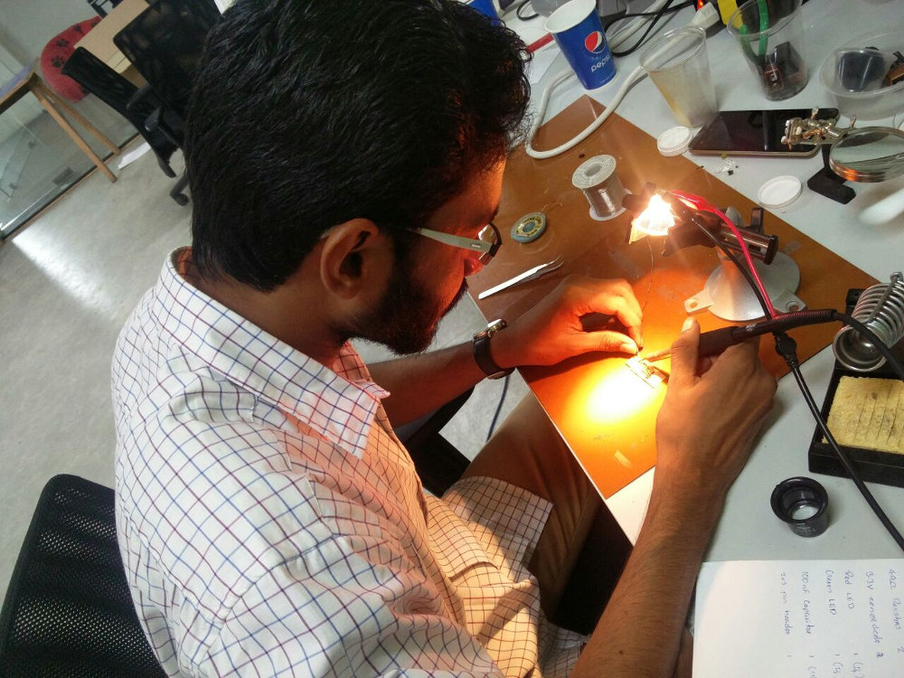
Soldering
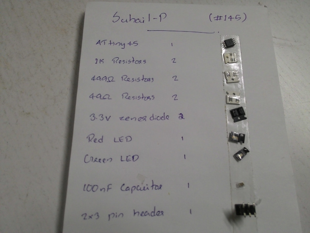
Now we have to solder the components on the board. I wrote down all the components name on a paper and used a double side tap to avoid mixing the SMD components. I started soldering IC first and kept 6 pin header for last, so that header wont block other items.
Programming
For installing necessary modules, use the code below,
sudo apt install avrdude gcc-avr avr-libc make
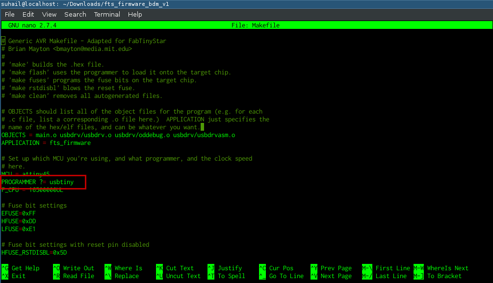
I downloaded firmware from here. After extracting, I moved into the folder. Its time to burn the firmware into the chip. For this we use another programmer. The programmer is connected to PC and the ISP is connected to programmer using IDC cable.
Go to the firmware directory and check if Makefile contains 'PROGRAMMER' as 'usbtiny'.
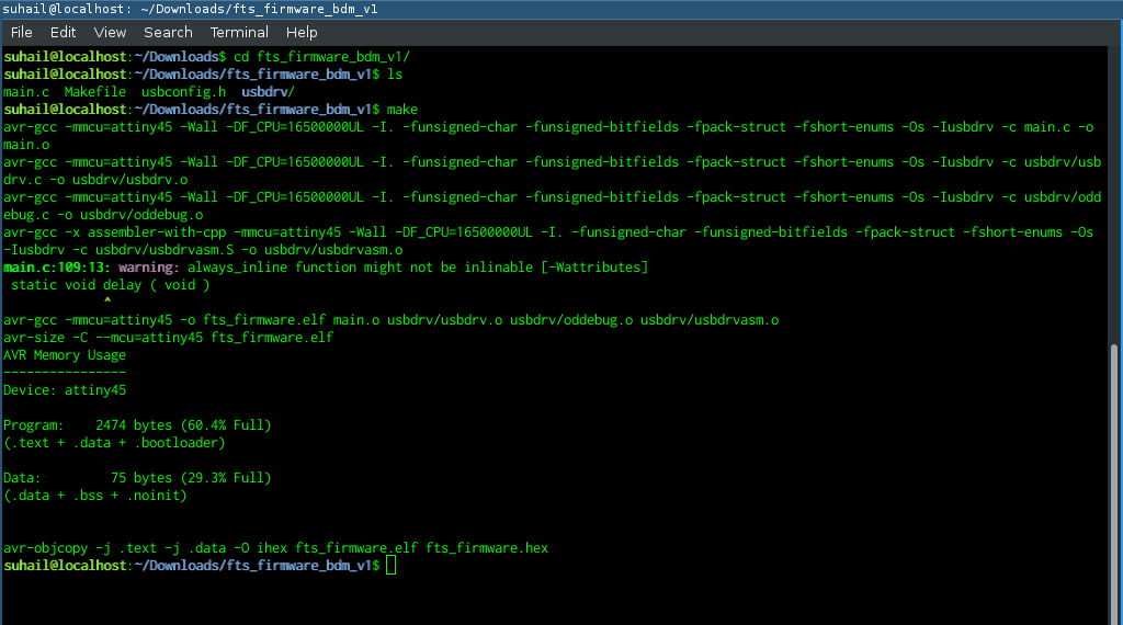
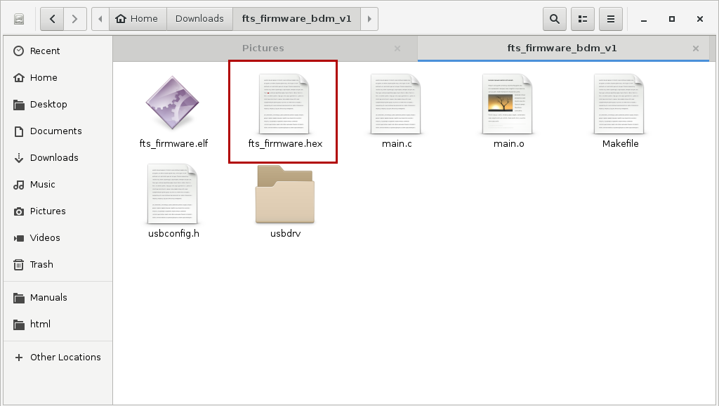
Run make command to generate hex file. After running this command our directory now contain a file named fts_firmware.hex.
make
Run make flash to flash hex file to the chip.
sudo make flash
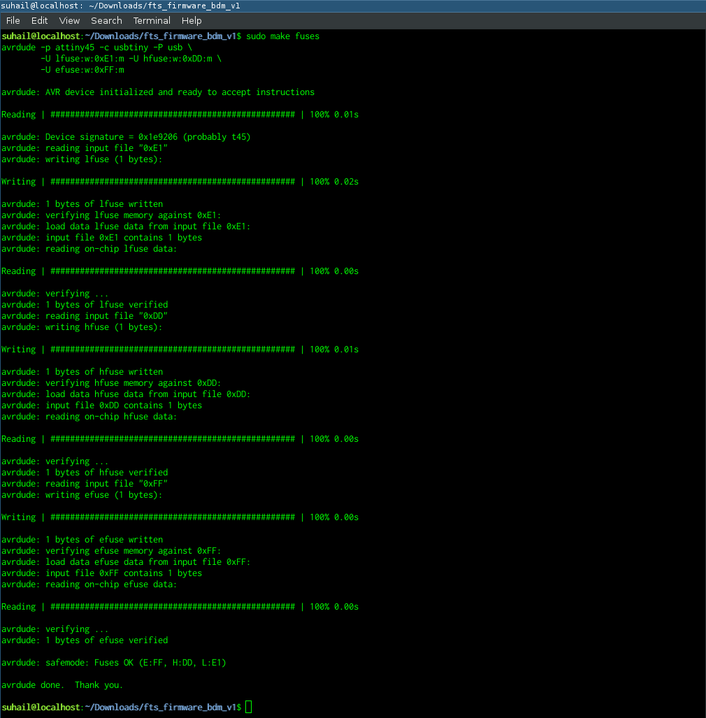
Run make fuses to setup the fuses.
sudo make fuses
Testing
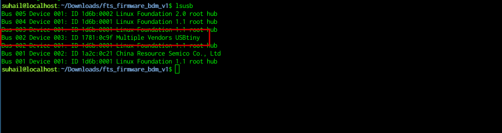
I removed my ISP from programmer and connected it directly to my PC and LED was turned on. Now, to check if system is detecting the usb device, I used lsusb command. This should list all the usb devices connected. dmesg command might be useful to check if there are any issues with the device. This command prints kernal messages.
lsusb
dmesg
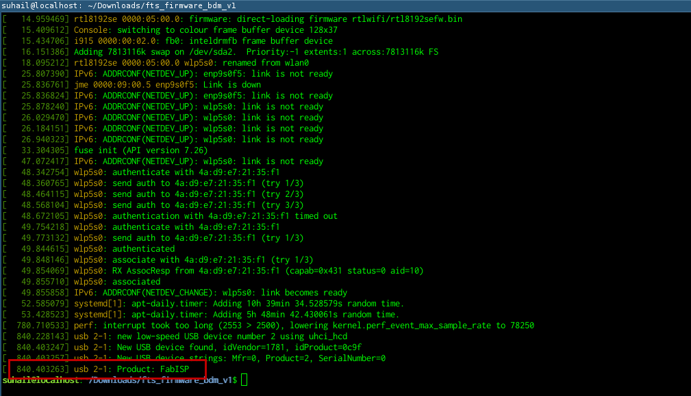
Now my ISP is being detected by the system. So its working fine. Now, I am going to disable the reset pin so that I can use it as an IO pin.
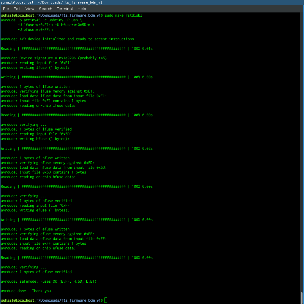
Disable Reset
To disable the reset pin run the command make rstdisbl.
sudo make rstdisbl
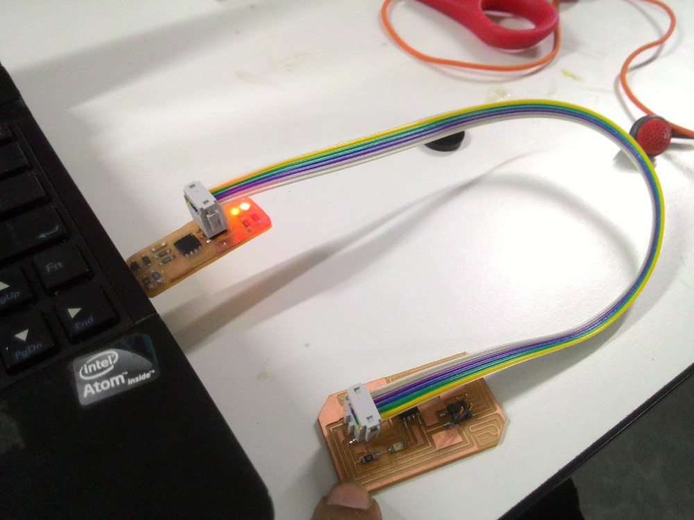
Testing
To check if my ISP can read other board, I connected another board into my ISP, and I used the below commands.
sudo avrdude -c usbtiny -b 9600 -p t45 -v
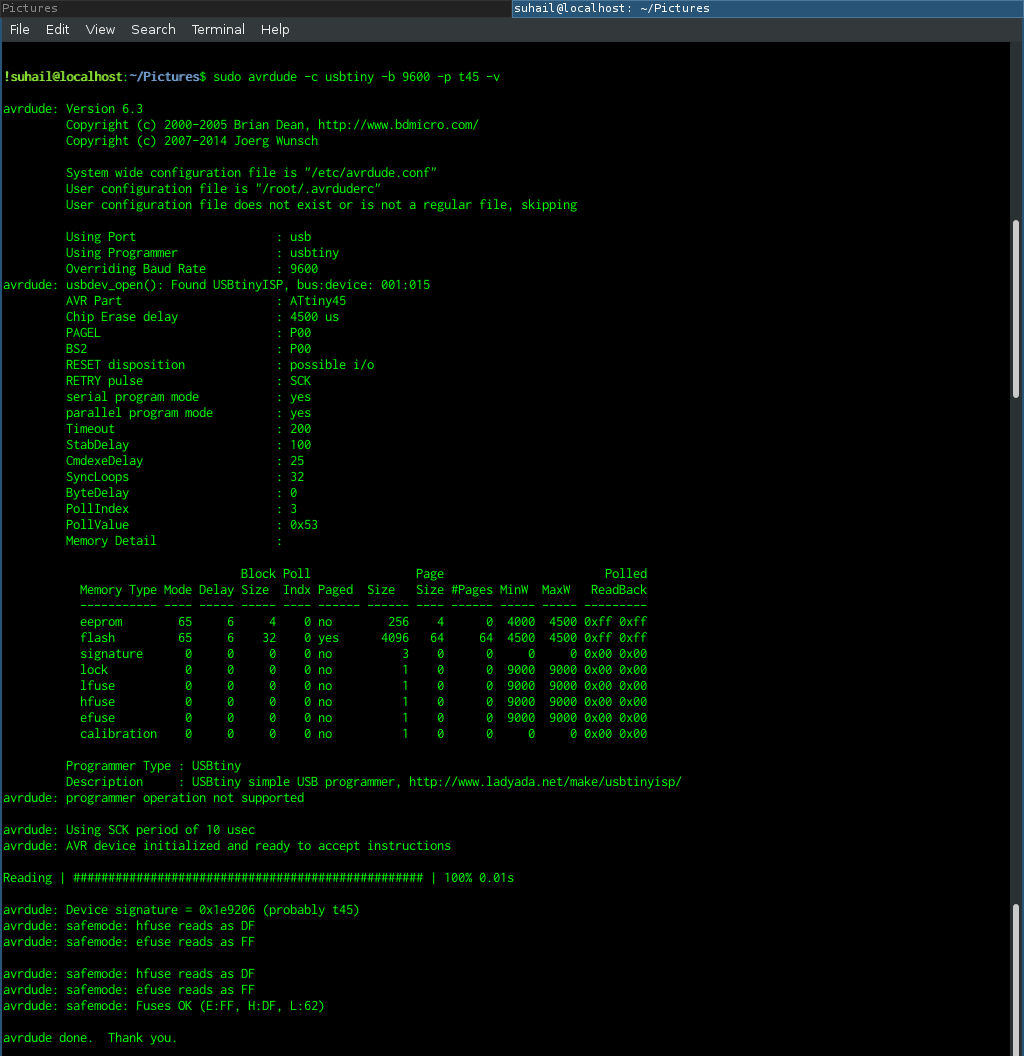
In the end its reading fuse values of the other board.
Final Thoughts
make flash command was showing errors. But using sudo fixed the issue.

The device was not properly fitting in the usb port initially. So I had to use thick vinyl cut pieces to increase thickness.
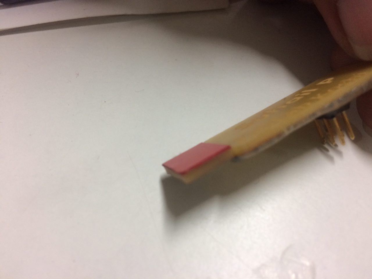
I made the USB contacts flat using a file, to avoid damaging my USB port.
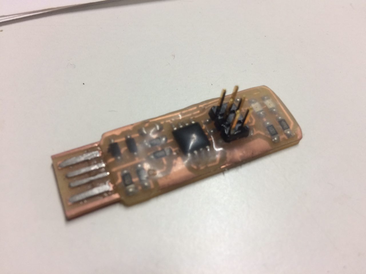
I added an extra protection layer using hot glue. Also laser etched my name on the back side of the board, for fun :)
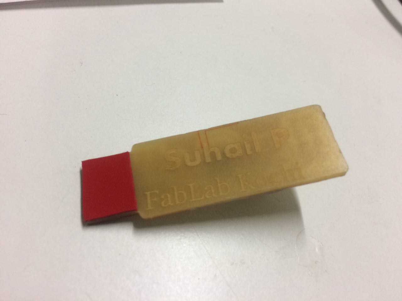
Final Product