
- This week's lecture : Lecture
- Fab Tutorial Link : Tutorials
- Fab Tool's List : Tools List
Assignments:
- read a microcontroller data sheet
- program your board to do something, with as many different programming languages and programming environments as possible
- extra credit: experiment with other architectures
What I did this week?
- Identified relevant informations from microcontroller data sheet.
- Programmed the board
- LED blinking
- LED ON as long as switch is pressed (and viceversa)
- Toggle LED status when switch is pressed
- Experimented with different environments
- Arduino programming using arduio IDE
- AVR-C programming in arduino IDE
- AVR-C in normal text editor, compiled and flashed using avr-gcc and avrdude
This week was all about programming the board we had designed in week-6(electronic design). I have some experience in electronic designs and embedded programming. But it was 3 years ago :). I have almost forgot everything. I am going to start (almost) from scratch.
I went through some random tutorials online, to get started. Then I started reading the datasheet for ATtiny44 chip. To be honest, I hate reading datasheets :). But I had no choice. ATTiny44 pin out diagram is below.
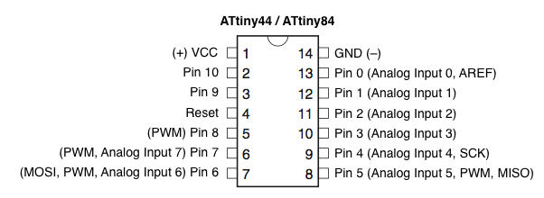
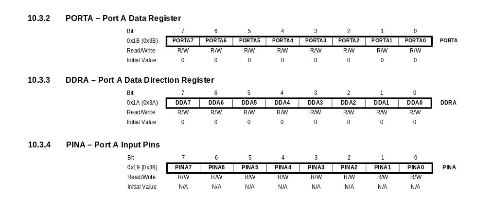
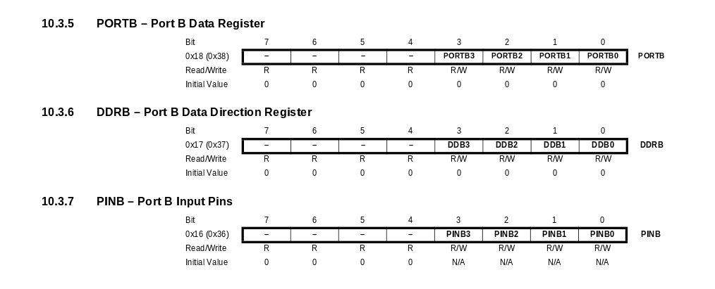
I had already set the fuse bits to use external 20MHz. Now, to start writing the program, its necessary to familiarise attiny44 ports and data registers. According to datasheet, ATtiny44 chip has two ports - PORTA and PORTB. Datasheet says "Port A is a 8-bit bi-directional I/O port" and "Port B is a 4-bit bi-directional I/O port". So, PORT-A has 8 pins and PORT-B has 4 pins. All these pins are general input output pins. Here are the pins, data register and data direction register of port A & port B.
I had connected LED at PA2 and switch at PA3. As per my design, switch is in floating condition. So I have to activate internal pullup for PA3. In datasheet, under the section pin descriptions it is clearly mentioned that internal pullup resistors are available in both PORTA and PORTB.
I have pointed out page numbers containing usefull information below.
- Pin description - page 2
- Interrupts - page 48
- Alternate Functions of Port A - page 61
- Alternate Functions of Port B - page 65
- I/O Ports Register Description - page 67
- 8-bit Timer/Counter0 with PWM - page 69
- 16-bit Timer/Counter1 - page 87
Note: Page numbers may change
1. AVR-C with avr-gcc and avrdude
I decided to try avr-c before going to arduino. I used emacs editor for coding, avr-gcc for compiling, and avrdude for flashing the program into the board. Four types of codes I used are below.
Blinking LED
/* This program will blink the LED with a delay of 50ms. LED at PORTA PIN2 */ #include<avr/io.h> #define F_CPU 20000000 //CPU frequency to use 20MHz #include<util/delay.h> #define DELAY_TIME 50 //constant value for delay - 50ms int main(void) { DDRA |= (1<<PA2); //1<<PA2 is 0b00000100 // infinite loop while(1) { //LED ON initially PORTA = 0b00000100; _delay_ms(DELAY_TIME); //set LED OFF PORTA = 0b00000000; _delay_ms(DELAY_TIME); } }- #define is used for declaring constant values
- DDRx stands for Data Direction Register, which is used for configuring Data Direction (input/output) of the port pins.
- PORTx is for writing the values to the pins in output mode.
- PINx is for reading the values from the pins in input mode.
compiling and flashing is done using the below commands.
$ avr-gcc -g -Os -mmcu=attiny44a -c blinking-led.c
$ avr-gcc -g -mmcu=attiny44a -o blinking-led.elf blinking-led.o
$ avr-objcopy -j .text -j .data -O ihex blinking-led.elf blinking-led.hex
$ sudo avrdude -c usbtiny -p t44 -U flash:w:blinking-led.hex
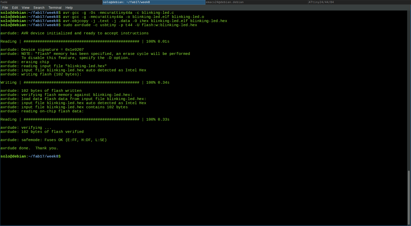
Output
LED action with switch
/*
This program is meant to ON the
LED when the switch is pressed.
LED at PORTA PIN2
Switch at PORTA PIN3
*/

#include<avr/io.h>
#define F_CPU 20000000 //CPU frequency to use 20MHz
#include<util/delay.h>
#define DELAY_TIME 5   //contstant value for delay 5ms

int main(void) {
    DDRA = 0b00000100;  // LED at A.2
        PORTA = 0b00001000; // pullup switch at A.3 & OFF LED at A2
        // infinite loop
        while(1) {
            if(!(PINA & 0b00001000)) {   // when button pressed
                    PORTA |= 0b00000100;     // turn ON LED
                    _delay_ms(DELAY_TIME);   // to manage switch action delay
                }
                else {
                    PORTA &= 0b11111011;     // turn OFF LED
                    _delay_ms(DELAY_TIME);   // to manage switch action delay
                }
        }
}
compiling and flashing is done using the below commands.
$ avr-gcc -g -Os -mmcu=attiny44a -c switch-blink.c
$ avr-gcc -g -mmcu=attiny44a -o switch-blink.elf switch-blink.o
$ avr-objcopy -j .text -j .data -O ihex switch-blink.elf switch-blink.hex
$ sudo avrdude -c usbtiny -p t44 -U flash:w:switch-blink.hex
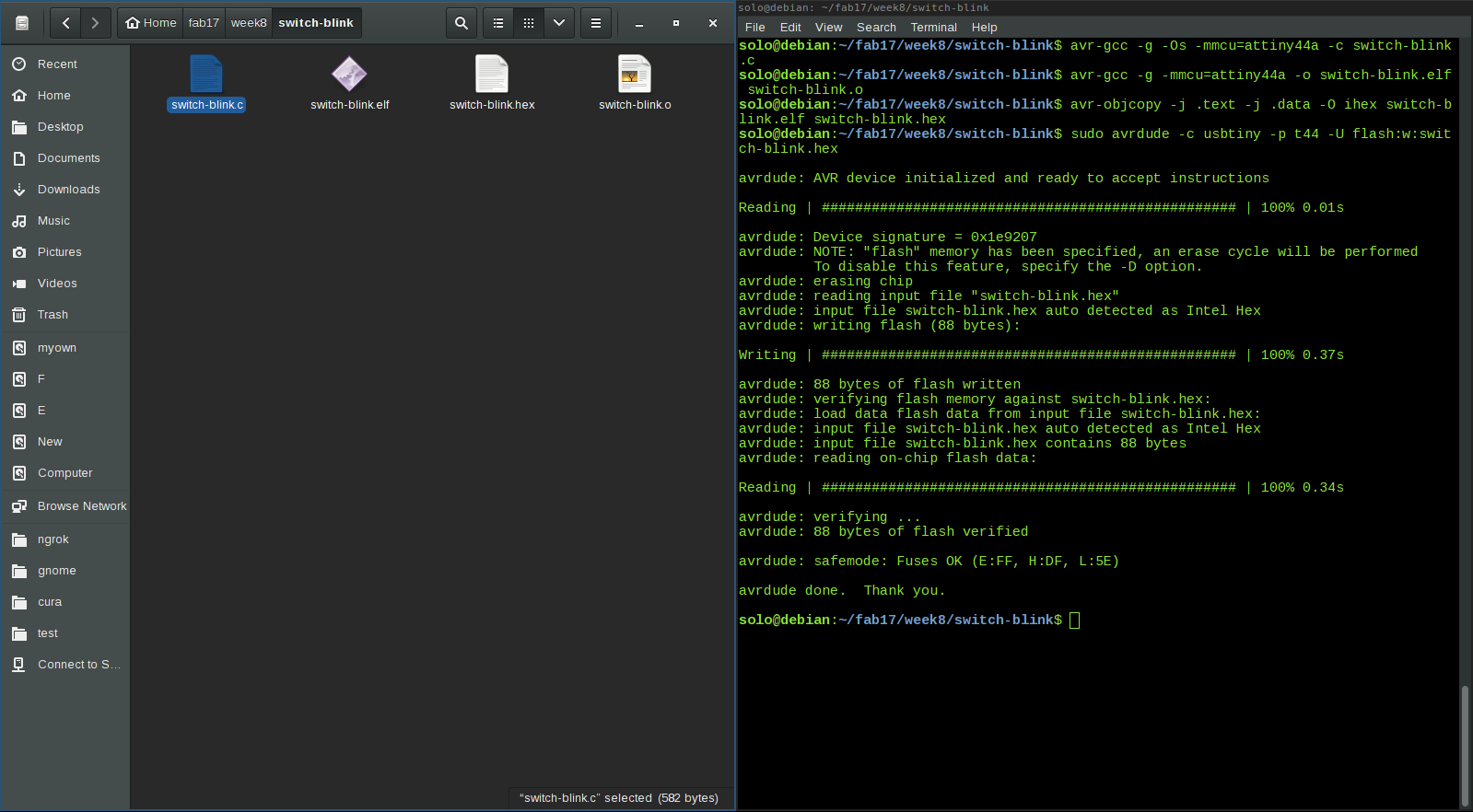
Output
LED action with switch - Inverse
/*
This program is meant to OFF the
LED when the switch is pressed.
LED at PORTA PIN2
Switch at PORTA PIN3
*/

#include<avr/io.h>
#define F_CPU 20000000 //CPU frequency to use 20MHz
#include<util/delay.h>
#define DELAY_TIME 5   //contstant value for delay 5ms

    int main(void) {
    DDRA = 0b00000100;  //LED at A.2
    PORTA = 0b00001100; //pullup switch at A.3 & ON LED at A2
    // infinite loop
        while(1) {
            if(!(PINA & 0b00001000)) {  //when button is pressed
                PORTA &= 0b11111011;    //turn the LED OFF
                _delay_ms(DELAY_TIME);  //to manage button action
            }
            else {
                PORTA |= 0b11110111;    //turn the LED ON
                _delay_ms(DELAY_TIME);  //to manage button action
            }
        }
}
compiling and flashing is done using the below commands.
$ avr-gcc -g -Os -mmcu=attiny44a -c switch-blink-inverse.c
$ avr-gcc -g -mmcu=attiny44a -o switch-blink-inverse.elf switch-blink-inverse.o
$ avr-objcopy -j .text -j .data -O ihex switch-blink-inverse.elf switch-blink-inverse.hex
$ sudo avrdude -c usbtiny -p t44 -U flash:w:switch-blink-inverse.hex
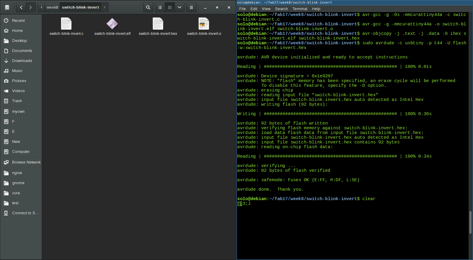
Output
Toggle LED status with switch
/*
This program is meant to toggle the
LED status when the switch is pressed.
LED at PORTA PIN2
Switch at PORTA PIN3
*/

#include<avr/io.h>
#define F_CPU 20000000 //CPU frequency to use 20MHz
#include<util/delay.h>
#define DELAY_TIME 5   //contstant value for delay 5ms

int main(void) {
    DDRA = 0b00000100;  // LED at A.2
        PORTA = 0b00001000; // pullup switch at A.3 & OFF LED at A2
        // infinite loop
        while(1) {
            if(!(PINA & 0b00001000)) {  // when button pressed
                    PORTA ^= (0b00000100);  // toggle LED status
                    _delay_ms(DELAY_TIME);  // to manage switch action delay
                }
        }
}
compiling and flashing is done using the below commands.
$ avr-gcc -g -Os -mmcu=attiny44a -c led-toggle.c
$ avr-gcc -g -mmcu=attiny44a -o led-toggle.elf led-toggle.o
$ avr-objcopy -j .text -j .data -O ihex led-toggle.elf led-toggle.hex
$ sudo avrdude -c usbtiny -p t44 -U flash:w:led-toggle.hex
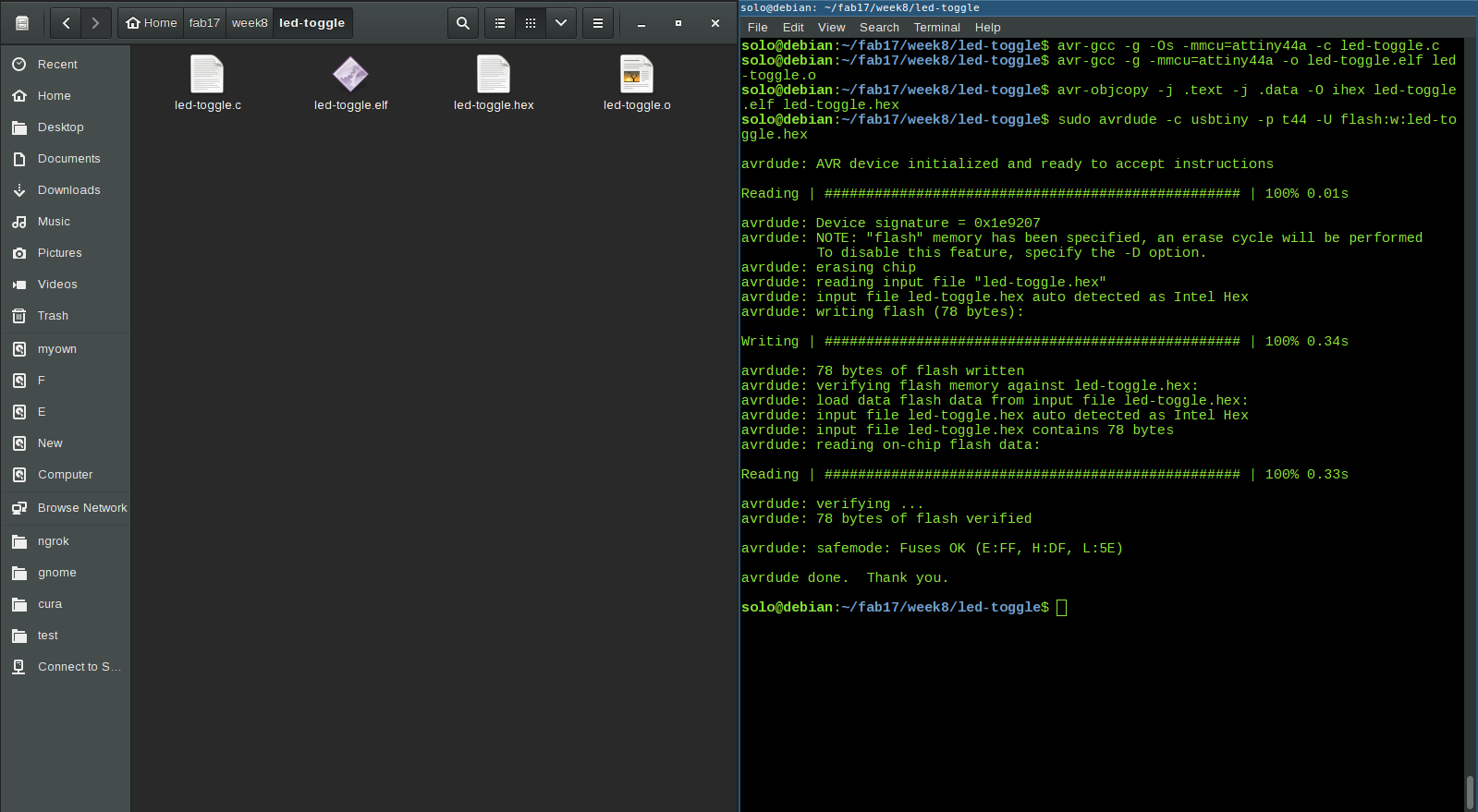
Output
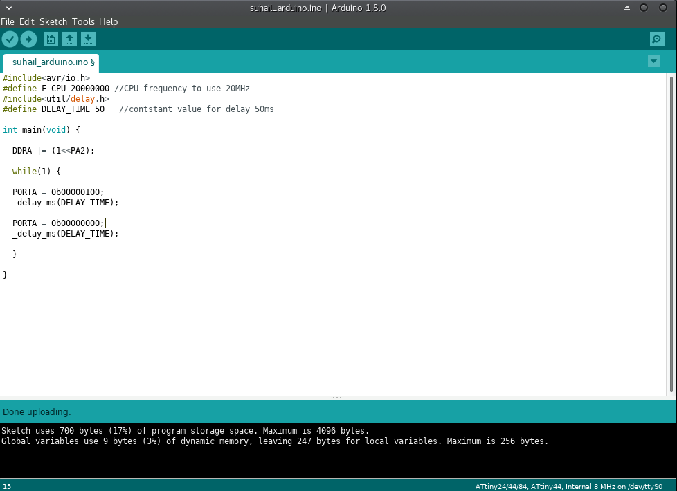
2. AVR-C compiled and flashed using arduino IDE
In previous section I used AVR-C and compiled using avr-gcc. Program was burned using avrdude. Now I am going to burn the same program written in avr-c using arduino IDE. Arduino IDE has graphical interface and its easy to compile and burn by clicking corresponding buttons. I followed this tutorial to add ATtiny44 support in arduino.
3. Arduino programming
Now I am going to use arduino programming(using Processing Language) for blinking the LED. I edited the existing Blink program. The code is given below.
/*
This program is for blinking the LED.
LED at PORTA PIN2
*/

void setup() {
    pinMode(2, OUTPUT);
}

void loop() {
    digitalWrite(2, HIGH);   // turn the LED on
    delay(500);              // wait
    digitalWrite(2, LOW);    // turn the LED off
    delay(500);              // wait
}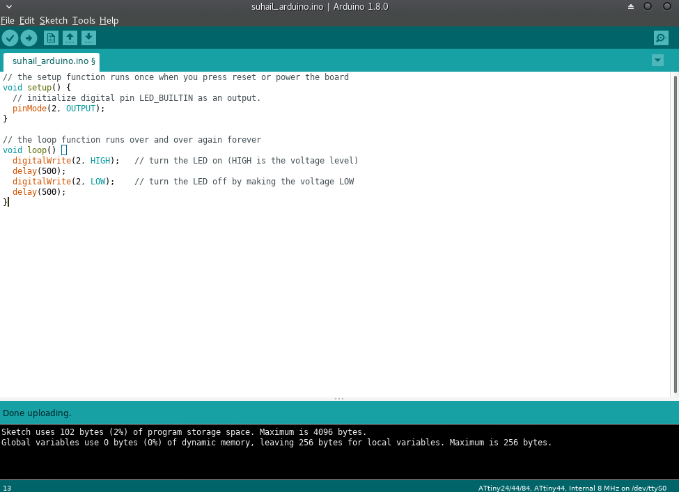
Final Thoughts
I have learned a lot this week. I tried different environments for programming. But I didn't get enough time to try programs using interrupts. How to do program using interrupts? I will explore this later. I would like to learn assembly language next.