3D SCANNING AND PRINTING
ASSIGNMENT
- Design and 3D print an object that could not be made subtractively.
- 3D scan an object and optionally print it (extra credit if you make your own scanner)
TESTING THE 3D PRINTER'S LIMITS: TOLERANCE TESTS
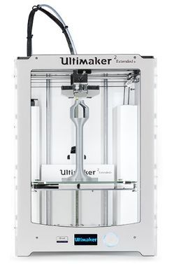
For this assignment I tested the tolerance of the Ultimaker 2 Extended+.
I decided to do the ultimate test of speed and results with high layer height and 0.8mm nozzle, as there are already many tests online for the same machine on 0.25mm and 0.4mm nozzles at high resolution.
I proceed with printing the test files. I used for this purpose, a general test file available at: https://www.thingiverse.com/thing:1363023, it tests for:
Nut size m4, wave patterns, sharp edges (star), holes (3mm, 4mm, 5mm), z height, brdiges, sphere, overhangs, flatness and retract travel.
I also used the so popular 3D benchy test model, available here:
3D Benchy modelTHe 3d benchy test is usually used for testing and benchmarking 3D printers. As not many tests in the market have been done with 8mm extruders and 0.5mm layer height, I decided to do so.
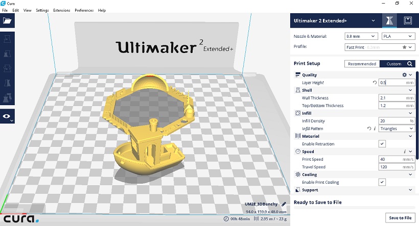
The slicer program used is Cura with the following settings:
Nozzle: 8mm
Material: PLA
Layer height: 0.5mm
Wall thickness: 2.1mm
Top/Bottom thickenss: 1.2mm
Infill density: 20%
Infill pattern: Triangles
Enable retraction
Print speed: 40 mm/s
Travel speed: 120 mm/s
Enable printer cooling
Both printed pieces are layed close to each othre and the approximate time of completion is of 50 minutes.
Print process can be appreciated in the video below:
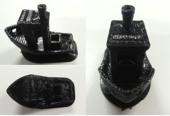
The 3D benchy printout came out surprisingly accurate, despite the 0.5mm height.
The benchy result showed lightly noticeable retraction issues, as well as, minor pitting along base layers.
In terms of overhangs, they were slightly droopy. High speed first layer printing led to some curled corners.
The smoothness of the surface, as expected due to the layer height, was rough; nevertheless, the overall shape and figure of the benchy was acceptable for a super rapid prototype.
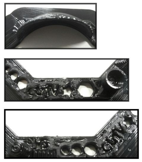
As for the tolerance printout at 0.5mm, I expected it to fail most of the tests; however, the overall shape was surprisingly still intelligible.
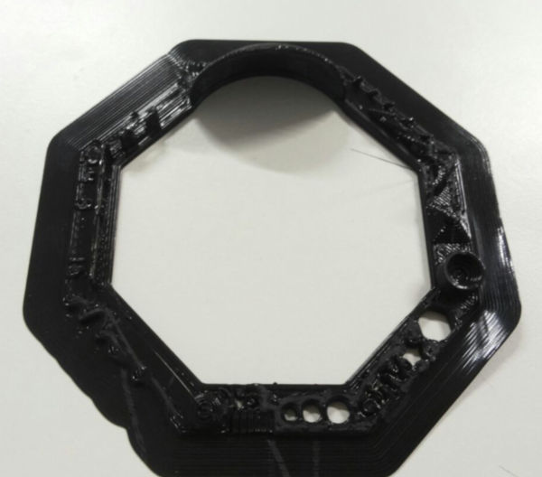
There was general warping and slight bending at the corners. The spike tests failed and the 3, 4, 5 mm. holes were significantly smaller.
The wave pattern was still visible and the sharp corners suffered slight curvature due to the resolution.
Other figures were visible but not clear.
This speed of printing might still be suitable for flash prototyping, however, it is not recommended for more detailed applications.
0.2mm height tolerance test
I decided to test a new printout of the tolerance tests using this time 0.2mm layer height.
The figure is layed in the middle using Cura with the following settings:
nozzle: 0.8mm
material: PLA
layer height: 0.2mm
wall thickness: 2.1
top/bottom thickness: 1.2
infil density: 15%
infil pattern: triangles
enable retraction
print speed: 40 mm/s
travel speed: 120 mm/s
enable print cooling
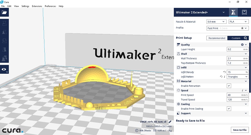
The buildplate is also heated to 70 degrees to improve adherence.
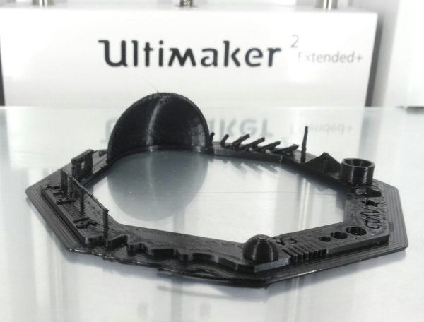
There was no printing issues with the nozzle and everything ran smoothly as before.
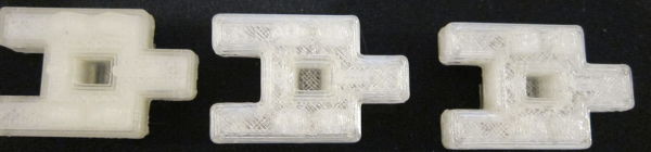
The quality of the printout, when compared to the previous test(in the yellow square), is significant. The holes and curvy tests and nuts are more precise in the higher resolution printout (green square), and holes are just about 0.4mm smaller than the real size; whereas, in the lower resolution print (0.5mm layer height), the holes are almost 1mm smaller.
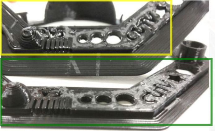
When compared to the previous result, at 0.2mm layer height resolution, the test partly passed the hole in a wall test and bridge connection tests.
As for the piramid test and spike test which failed at 0.5mm resolution; the test at 0.2mm resolution printed successfully visible figures, although not acceptable for high standards, it still shows that at 0.2mm the Ultimaker extended 2+ is capable of printing shapes with reasonable precision for rapid prototyping.
Interestingly, the dome printed with more artifacts in the higher resolution 0.2mm test, even at same travel and printing speeds.
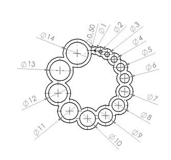
Hole test
Finally, I decided to print a hole test available here.
The settings for the printing were as follows:
nozzle: 0.8mm
material: PLA
layer height: 0.2mm
wall thickness: 2.1
top/bottom thickness: 1.2
infil density: 15%
infil pattern: triangles
enable retraction
print speed: 40 mm/s
travel speed: 120 mm/s
enable print cooling
Cura was also used to prepare the printout.
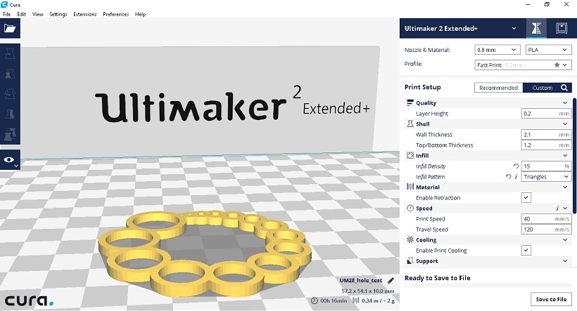
The piece printed as follows:
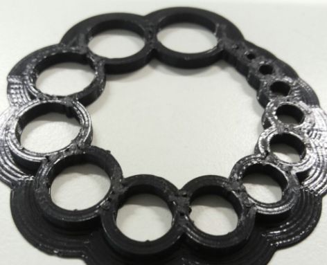
Next, holes are measured carefully 5 times and averaged out for each hole to reduce error..
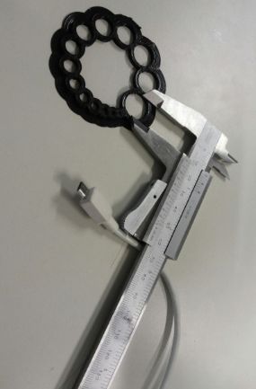
The measurements were as follows, notice that for smaller holes, the real sizes are over.
| EXPECTED | MEASUREMENT |
|----------+-------------|
| 14mm     | 13.3mm        |
| 13mm     | 12.3mm        |
| 12mm     | 11.5mm      |
| 11mm     | 10.8mm      |
| 10mm     | 9.2mm         |
| 9mm      | 8.2mm       |
| 8mm      | 7.8         |
| 7mm      | 6.4mm       |
| 6mm      | 5.8mm       |
| 5mm      | 4.7mm       |
| 4mm      | 3.8mm       |
| 3mm      | 3.2mm       |
| 2mm      | 2.3mm       |
| 1mm      | 1.5mm       |
| 0.5mm    | 0.2mm       |
|----------+-------------|
TESTING 3D PRINTER:LAYER HEIGHT AND INFILL
The lab's 3D printer I tested is the Ultimaker 2+ with a 0.8mm nozzle and PLA.
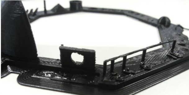
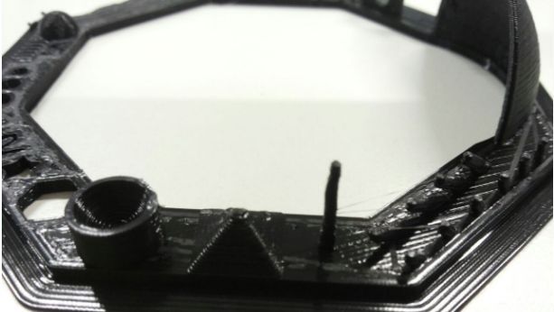
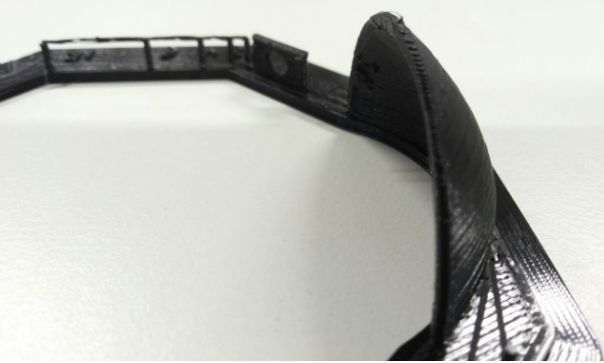
I tested the printer's constraints using one of my prototype designs for the tank treads made in week 2.
I found that the maximum optimal layer height for the 0.8mm nozzle to be about 0.6mm.
Similarly, hole sizes tended to be approximately 0.5mm smaller than the actual design.
Print speed was left constant at 30 mm/s and travel speed at 120 mm/s.
I also varied the infil density from 15% to 50%.
Settings in cura were as follows:
0.8mm nozzle PLA

QUALITY
layer height: 0.6mm / 0.4mm / 0.2mm (for 1st, 2nd, 3rd test)

SHELL
wall thickness: 2.1mm
top/bottom thickness: 1.2mm

INFIL
infil density: 50 % / 15% / 25% (for 1st, 2nd, 3rd test)

MATERIAL
enable retraction: TRUE

SPEED
print speed: 30 mm/s
travel speed: 120 mm/s

COOLING
enable print cooling: true

SUPPORT
enable support: true
support placement: touching buildplate
support overhang angle: 50
support pattern: triangles
support density: 10%
support x/y distance: 1.2mm
support z distance: 0.5mm

BUILD PLATE ADHESION
build plate adhesion type: brim
brim width: 8mm

PRINT SEQUENCE:
all at once
Picture below illustrates the printout results.
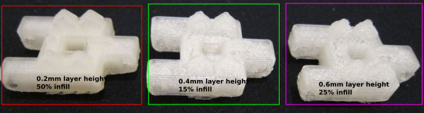
The apparent strength of the material at first sight does not appear to vary with manual tensile stress.
However, in order to decide the optimal percentage of infill, a test for mechanical strength is required; ABS is nevertheless more suited for such applications.
Lessons learnt from this week were taken further in my final project, see the final project 3D printing pagefor further details.
DESIGN OF 3D OBJECTS
I use Openscad to design a 3D object which could only be made additively.
Openscad is a 3D design software focused on parametrization and programmer friendly interface.
Openscad interface allows the user to model 3D objects using a functional programming language similar to C.
The following functions are used to model a simple 3D object:
translate([x,y,z])
rotate([x,y,z])
cube(size,center=true|false)
sphere(radius)
module name(foo){functions}
for(i=[start:step:end])
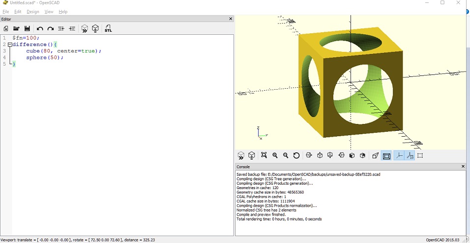
In order to model a sphere enclosed inside a complex cube-like shape, start with the outside.
First, a sphere is rendered using the sphere function.
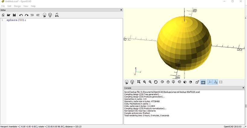
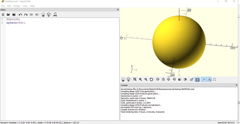
The variable $fn=100 defines the number of fragments that Openscad will render. The higher, the more 'sphere-like' the render will be, however the rendering time will take longer, especially for more complex objects.
A cube is later added with lower dimensions to the sphere and with the parameter 'center=true', so it appears in the center of the coordinate system.
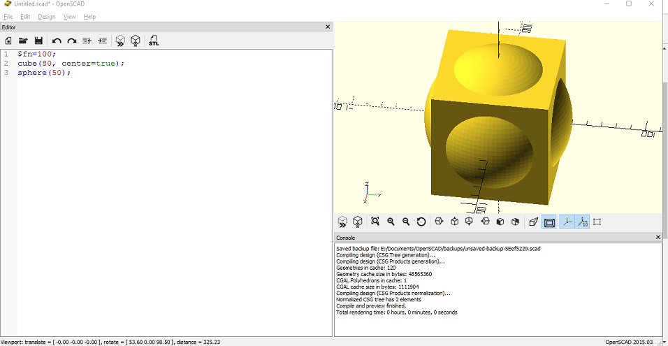
The difference operator is applied to both objects. The result is as follows:
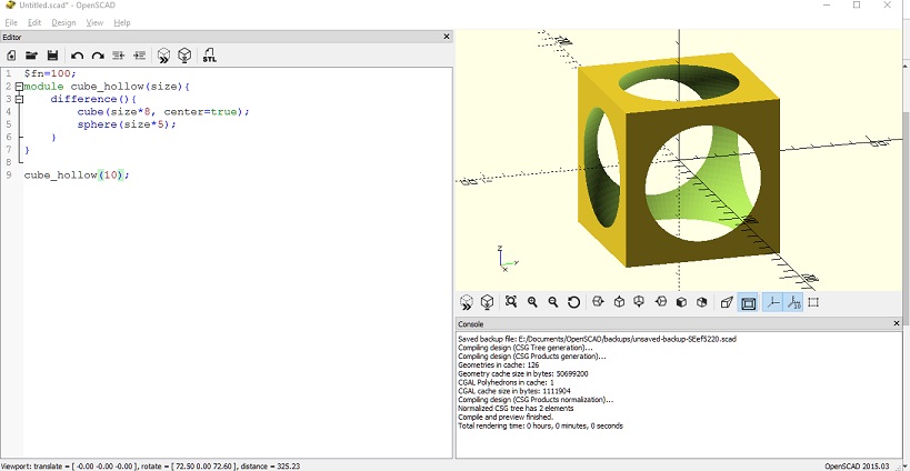
Openscad can create modules for pre-defined objects. A module is created for the object with one parameter size which will automatically resize the objects within the module function.
The new module cube_hollow can be easily added to the design by just typing the function with a value for the size parameter.
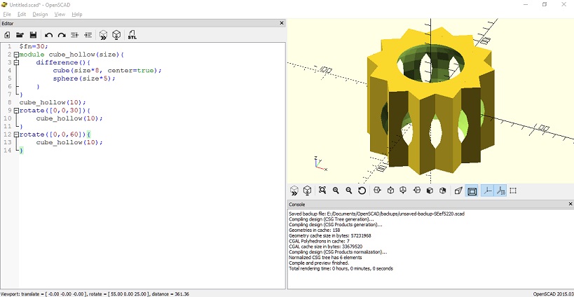
Next, two cube_hollow objects are added and rotated 30 and 60 degrees, respectively, around the z-axis.
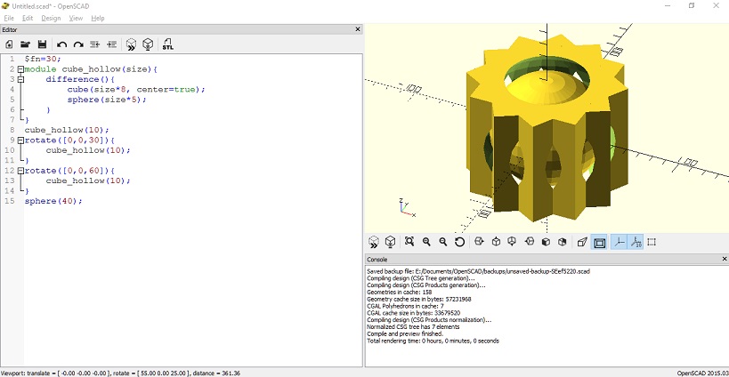
Finally, a sphere is drawn inside the object.
Aditionally, Openscad can also do for loops. In the following example, the cube_hollow module is generated repeatedly by a step-size of 2.
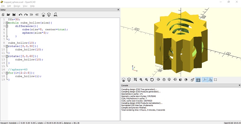
$fn=30;
module cube_hollow(size){
    difference(){
        cube(size*8, center=true);
        sphere(size*5);
    }
}
cube_hollow(10);
rotate([0,0,30]){
    cube_hollow(10);
}
rotate([0,0,60]){
    cube_hollow(10);
}
sphere(40);

//for(i=[2:2:8]){
//    cube_hollow(i);
//}
Ball bearing-like design
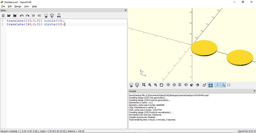
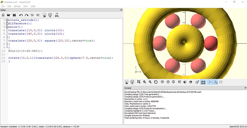
I wanted to try to design a ball bearing in OpenSCAD. OpenSCAD user manual is very comprehensive.
2 circles are drawn and translated using the translate() and circle() functions.
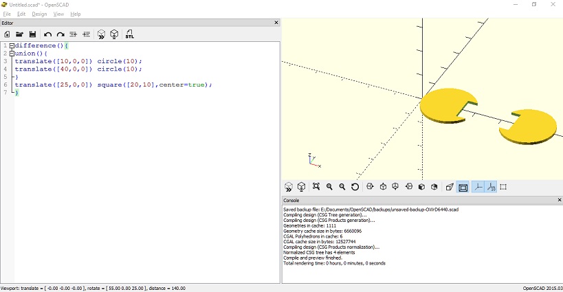
The two circles are differenced by a rectangle using the difference() operator. Note that the two circles were unioned before the difference operator is applied.
OpenSCAD has a very useful function called rotate extrude. It rotates a 2D shape 360 degrees around the Z-axis. One of the requirements is that the 2D shape is located outside the axis, on either the positive or negative side of the X axis.

A sphere is drawn and translated, the # operator in openSCAD highlights the newly drawn object, it is optional.
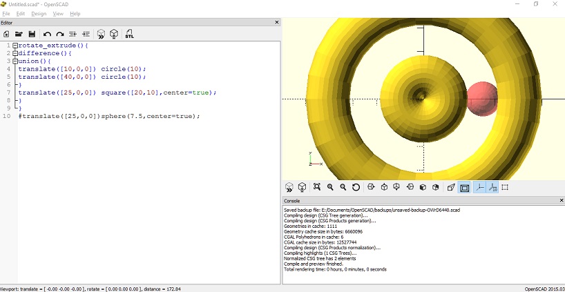
A for loop is used to generate equally spaced spheres, rotated around a 360 degree circle.
The final 3D design:
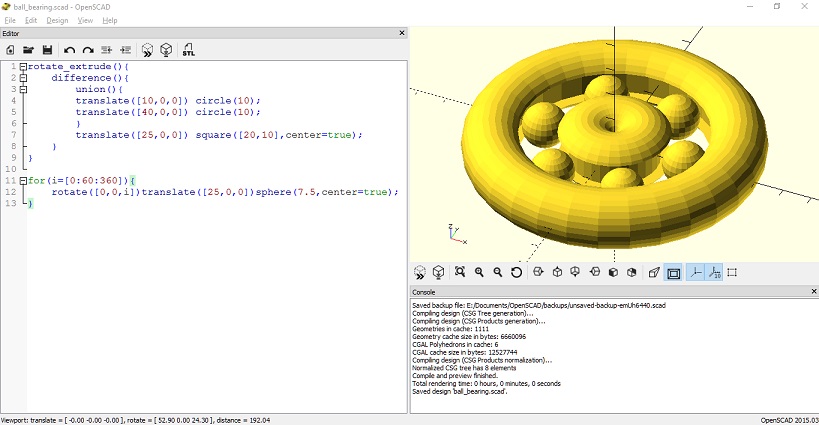
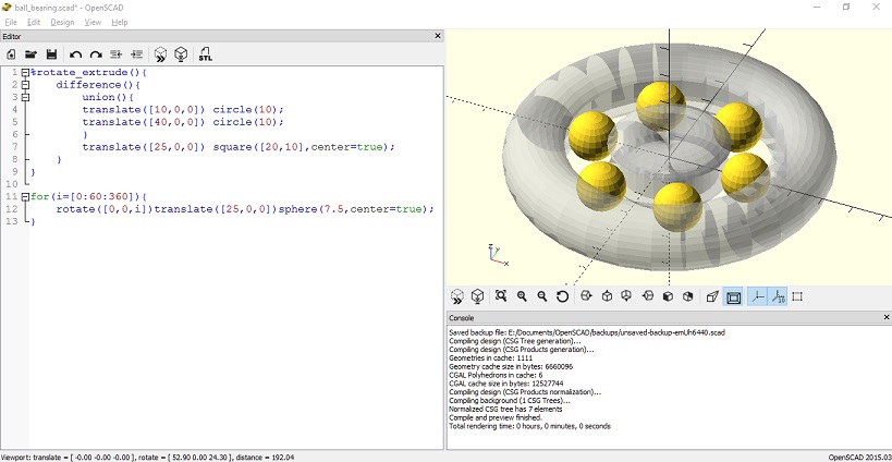
Any object can be made transparent by using the % modifier.
rotate_extrude(){
    difference(){
        union(){
        translate([10,0,0]) circle(10);
        translate([40,0,0]) circle(10);
        }
        translate([25,0,0]) square([20,10],center=true);
    }
}

for(i=[0:60:360]){
    rotate([0,0,i])translate([25,0,0])sphere(7.5,center=true);
}
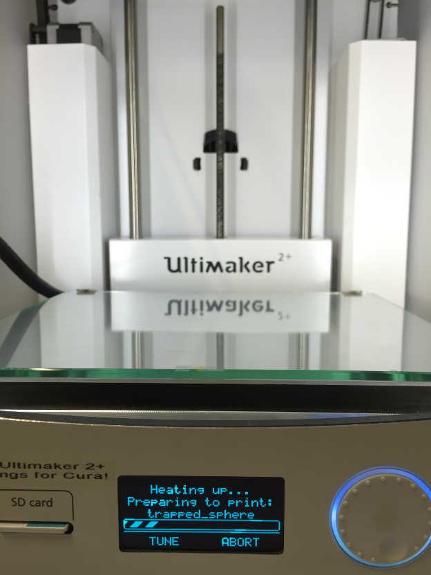
PRINTING AND FINAL RESULT
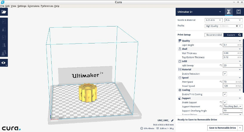
Ultimaker 2+ was used to print the design. The printer is very straightforward, it only needs a supported printing format to start the printing process.
CURA is used to prepare the printing job. Firstly, the design is saved as .STL in Openscad and imported into CURA.
Then, the corresponding printer is selected. In my case, the Ultimaker 2+.
I wanted a fast print, the following settings were applied in my first print:
layer height: 0.1mm
wall thicknes; 0.88mm
top/bottom thickness: 0.72mm
infill density: 20%
enable retraction
print speed: 70 mm/s
travel speed: 120 mm/s
enable print colling
enable support
support placement: touching buildplate
support overhang angle: 50
support pattern: grid
support density: 10
build plate adhesion type: Brim
brim width: 4mm
print sequence: all at once
Imported .stl image is scaled down by 25% and settings above applied.
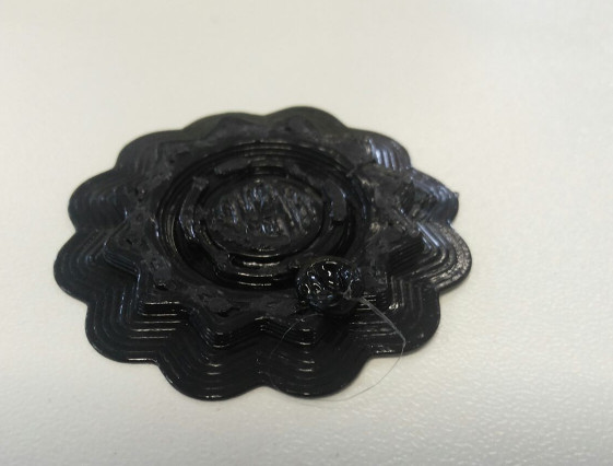
Using the roller button, I selected my file to print.
The extruder clogged, and the first 3D printout came out as follows:
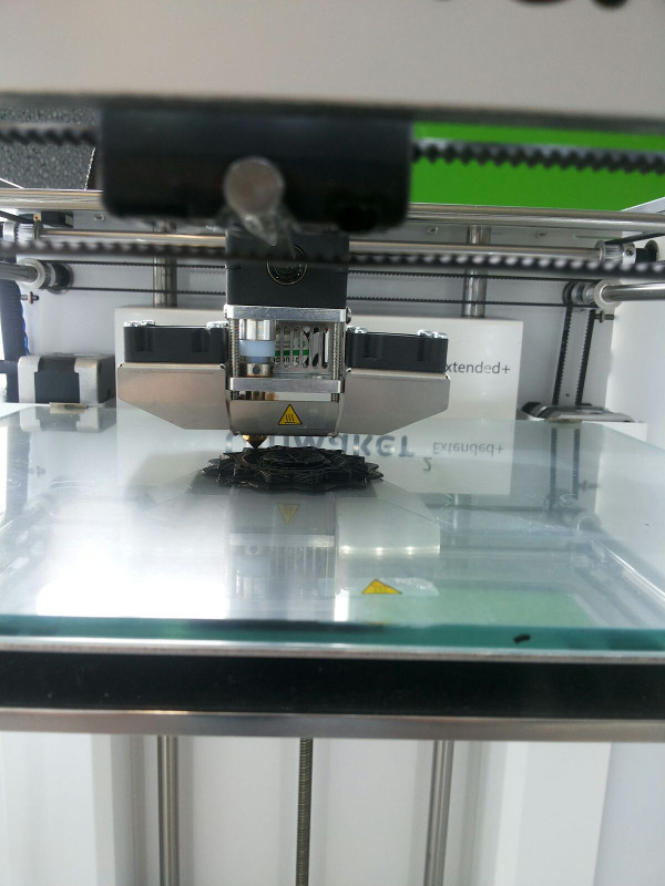
As the Ultimate 2+ was in use by another person, I decided to print again with the Ultimaker 2+ extended.
This printer in our lab has a 0.8mm Nozzle, it is considerably faster.
The setting used for this try were:
-NOZZLE AND MATERIAL-
0.8mm and PLA

-QUALITY-
layer height: 0.4mm

-SHELL-
wall thickness: 1.6mm
top/bottom thickness: 1.2

-INFILL-
infill density: 20%

-MATERIAL-
enable retraction:true

-SPEED-
print speed: 40 mm/s
travel speed: 120 mm/s

-COOLING-
enable print cooling: true

-SUPPORT-
enable support: true
support placement: touching buildplate
support pattern: triangles
support density: 15%
support X/Y distance: 1.2mm

-BUILD PLATE ADHESION-
build plate adhesion type: brim
brim width: 4mm
The layer height, about half of the nozzle will allow for faster printing.
the support placement as touching buildplate is so it is easier to remove the support later. Additionally, the support pattern are triangles and X/Y distance was increased to 1.2mm. As for the Brim, the width is of 4mm as the model base is not very big but it is small enough to allow the very thin parts at the bottom to stick better to the build plate.
First few layers seemed to print alright.
PRINTING RESULT
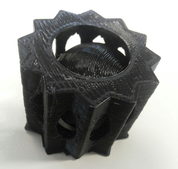
The quality of the print is low as the printing speed was fast. The sphere is contained inside the structure as expected and the support material was easy to remove. The support at the base however, was tricky to remove.
The integrity of the object was kept and the printing completed without any issues. The object is also sturdy to touch and the walls thick enough not to break.
VIDEO
SCANNING OF OBJECT
SENSE 3D scanner v1 is used to scan a chair in the fablab. The software is very straight forward to use. It requires good lightning and a 360 degree scanning of the object or person.
The chair was positioned on a table to allow the scanner to get as many angles as possible.
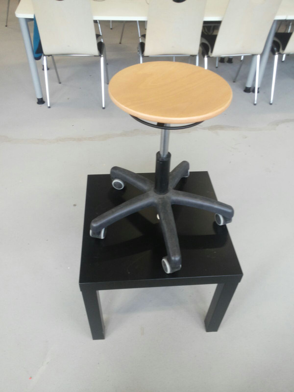
After careful scanning and allowing for only one colour, the scanned chair looked as follows:
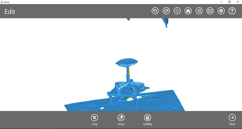
Sense's 3D scanning software allows the deletion of unwanted artifacts. I used the erase tool to remove imperfections.
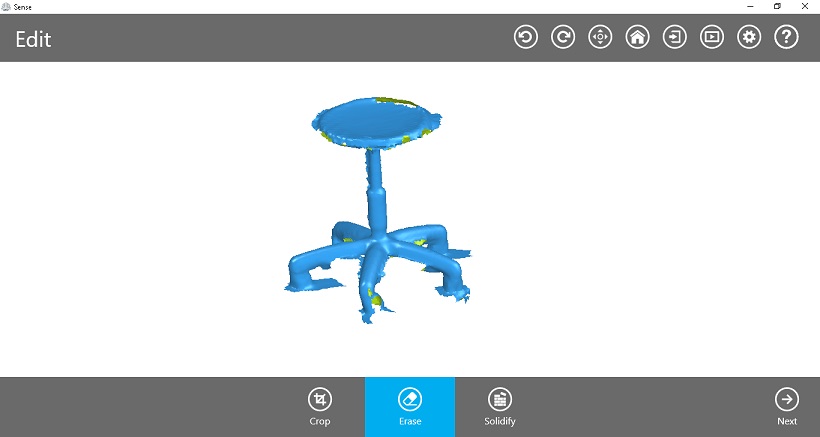
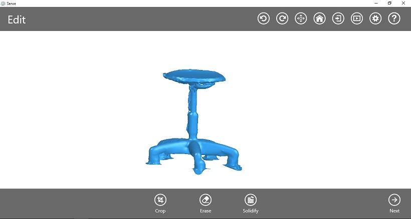
Once happy with the design, I proceeded with the solidification of the piece, using the 'solidify' button in the software UI.
PROBLEMS
LESSONS LEARNED
- Learned to use OpenSCAD
- Learned to troubleshoot 3D printing problems and print successfully on the Ultimaker 2+
- Experimented with 3D scanning.
FILES
OpenSCAD trapped sphere design
OpenSCAD ball bearing-like design