Week 03 - Computer-controlled Cutting
Menu
Computer-controlled cutting tools
Vinyl cutters are versatile tools if it comes to machining CAD parts. There is a great variety of tools to be covered, but for this week, we will focus on laser cutters as well as vinyl cutters. If have worked with laser cutters before, so I focussed on experimenting with the workflow of drawing a 3D part and translating it to format that the laser cutter is able to work with. So far only designed 2D part for the laser cutter in Inkscape.
No matter which computer-controlled cutting tool you will use in the future, there will always be two steps involved, the design process and the manufacturing process . I used Autodesk Fusion 360 as well as Inkscape for some final tweaking. I designed my parts with Fusion 360 and exported these in the common *.dxf standard. The laser cutter is working with vector graphics as well as raster graphics. The actual cutting is performed with vector graphics, rastering is needed for engravings. Engravings will be added with *.png graphics in Inkscape after the design process is finished. During the cutting process, a certain part of the material will be eaten by the laser - the so called kerf. The amount depends on the settings, e. g. speed, power and frequency as well as the material involved. The current state of the optics (e. g. clean, dirty, aged, brand new) will also have an effect on the overall result. As these effects cannot be fully predicted, in case of very precise fittings some trial are needed. These effects will be covered in the group assignment.

For vinyl cutting, there is no such thing as a kerf, as the tool tip performs a very thin and precise cut through a layer of vinyl, textiles, paper, etc. The vinyl cutter we will use - a Silhouette, model Portrait - is only able to cut. More advanced models included an embossing functionality for paper. I. e., as there is such thing as engraving, this vinyl cutter will only work with vector graphics.
So here are the tasks for Week 03:
- Design and cut a drawing with the vinyl cutter
- Design and cut a press fit kit with the laser cutter
- Group assignment about the kerf
Vinyl cutting
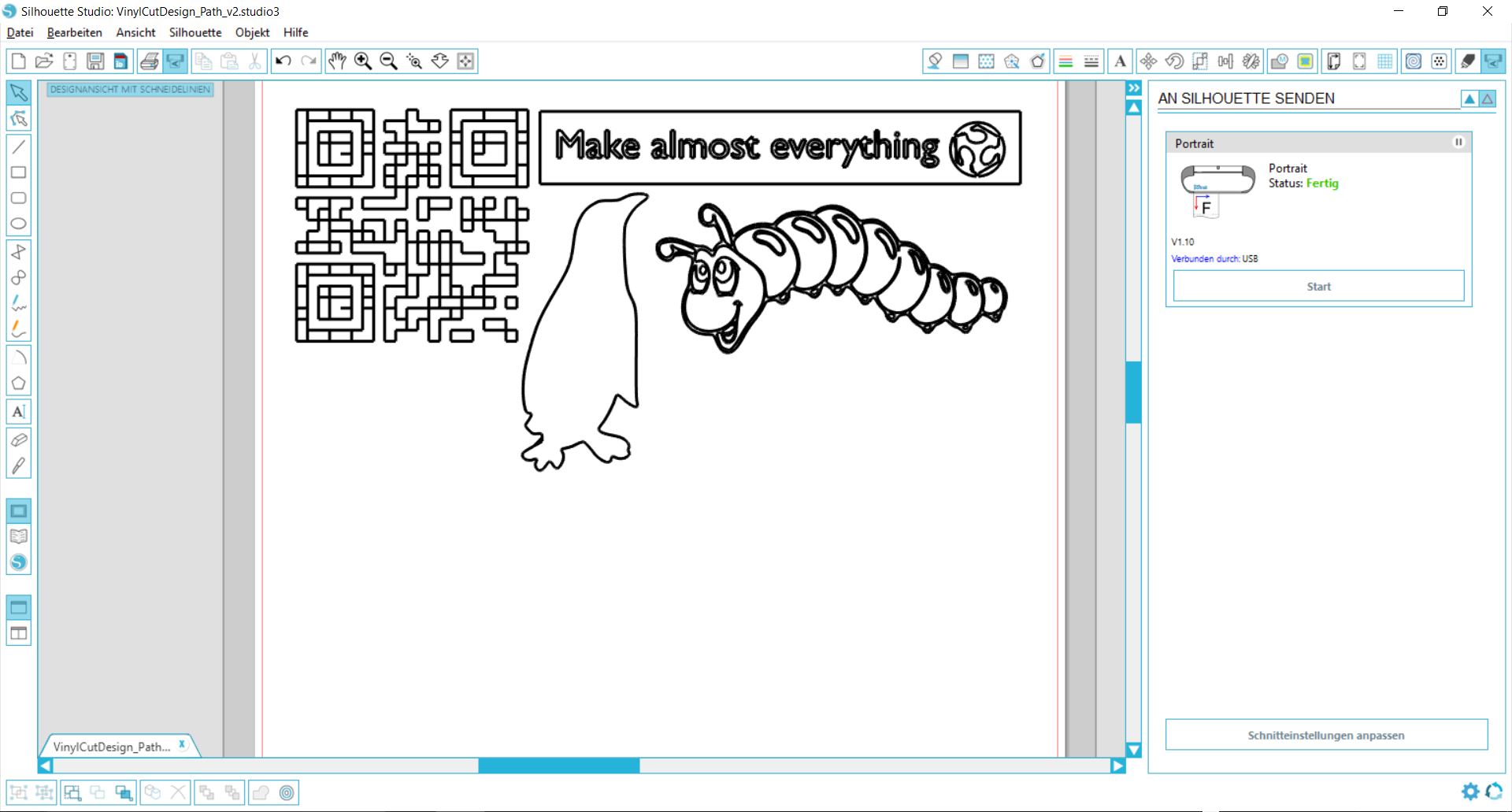
For vinyl cutting I created some simple forms in Inkscape by either using existing *.svg-files or applying the path -> trace bitmap function to create a vector format from a raster format. I used Silhouette Studio to send the file to the vinyl cutter.

Vinyl cutting settings
Silhouette studio does already a lot for you. As there are different printer sizes, make sure to choose the 8 inch carrier foil. If you import a *.dxf the size probably won't fit. In my case, I readjusted it manually. Within the cutting settings, you can then choose a material (in case vinyl). This will also propose a speed and a depth. As I use a different vinyl, I used a depth 16 instead of 10 proposed by Silhouette studio., speed 4 cm/s. Finally, I chose a knife set of 2.

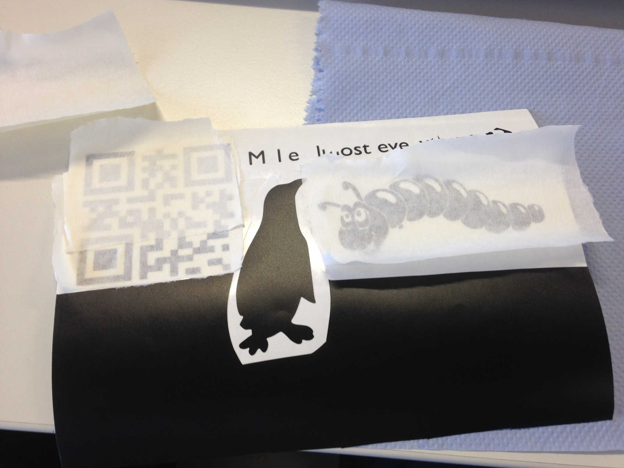
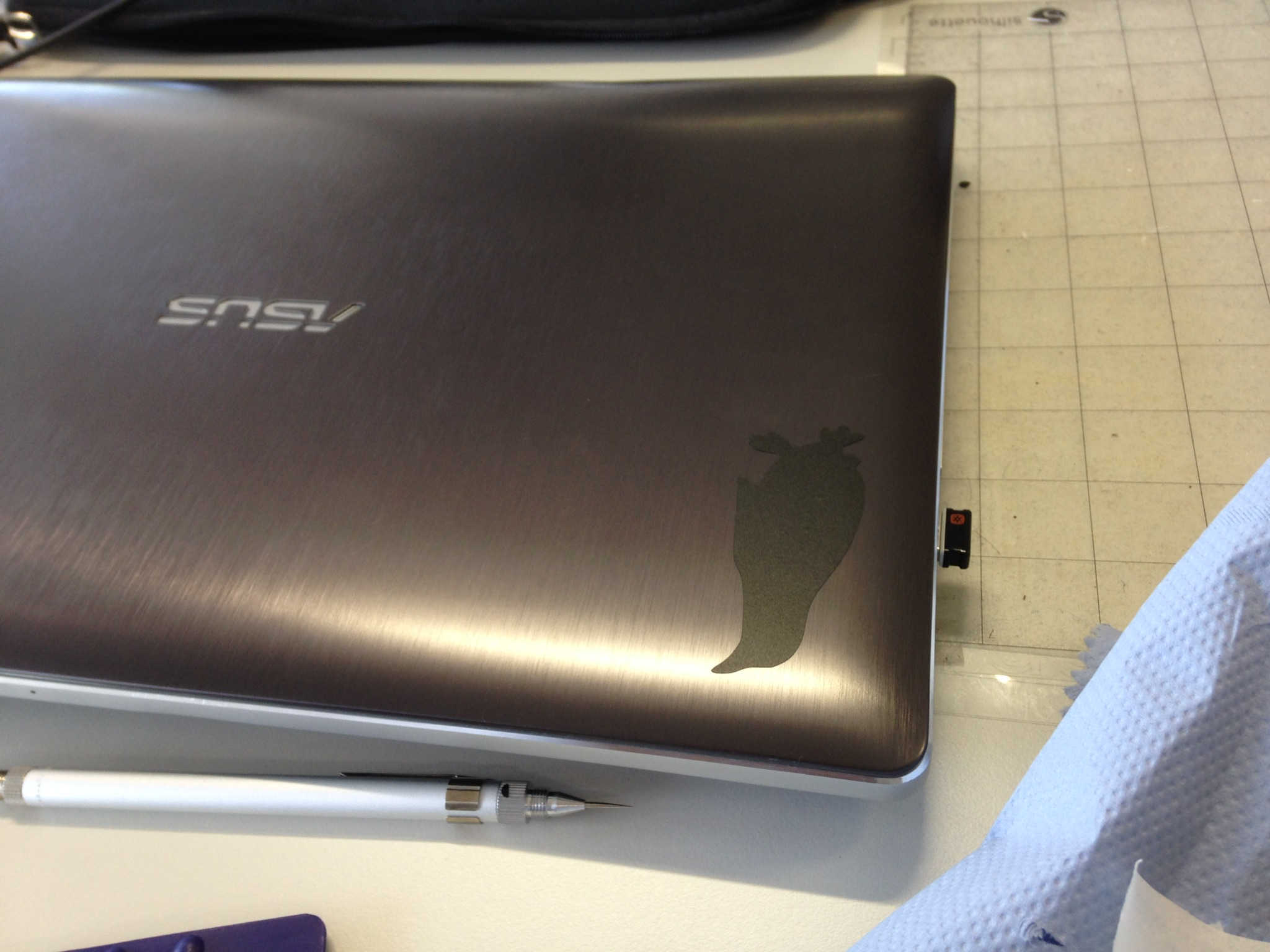
Vinyl cutting process


Laser cutting
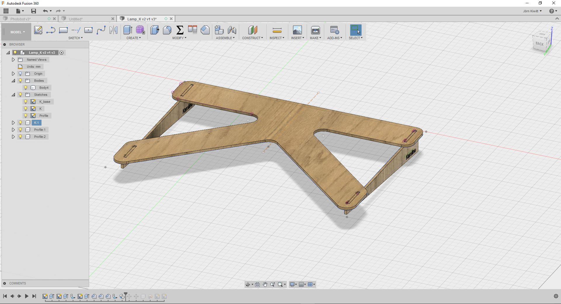
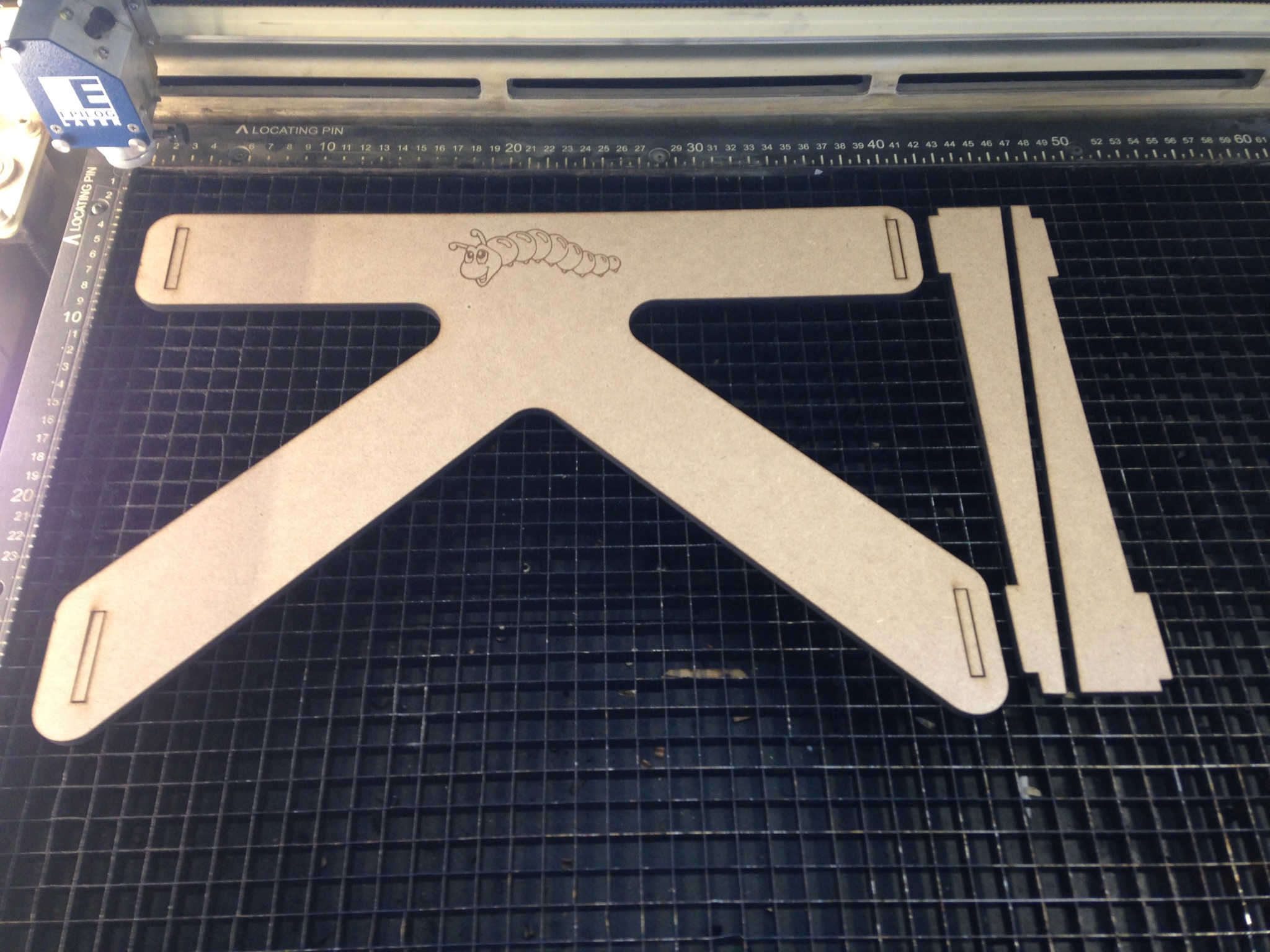
I started with a common task for a first pressfit kit, designing this stand for a laptop.By the way, to find out how to embed Fusion 360 files, follow this link.
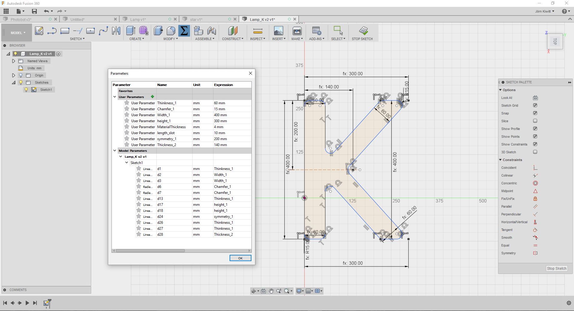
I tried to be flexible in the overall design, which is why I used a lot of user defined parameters. These are really simple to apply in Fusion 360 and will enable the adaption of your design according to your needs.

Design and CAM preparation
Sketch the initial shape and add dimensions to it.

Adduser defined parameters to change the shape later on, not having to do this one by one.
Extrude your sketch adding a parameter for the materials thickness.
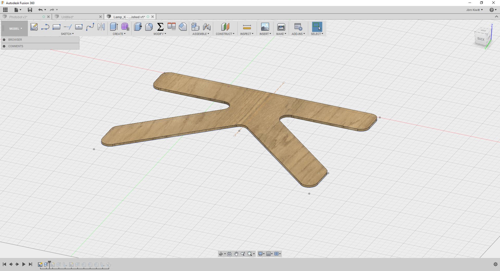
Pressfit slots can be added by designing one of them and of a rectangular pattern in the sketch bar to add the other ones.
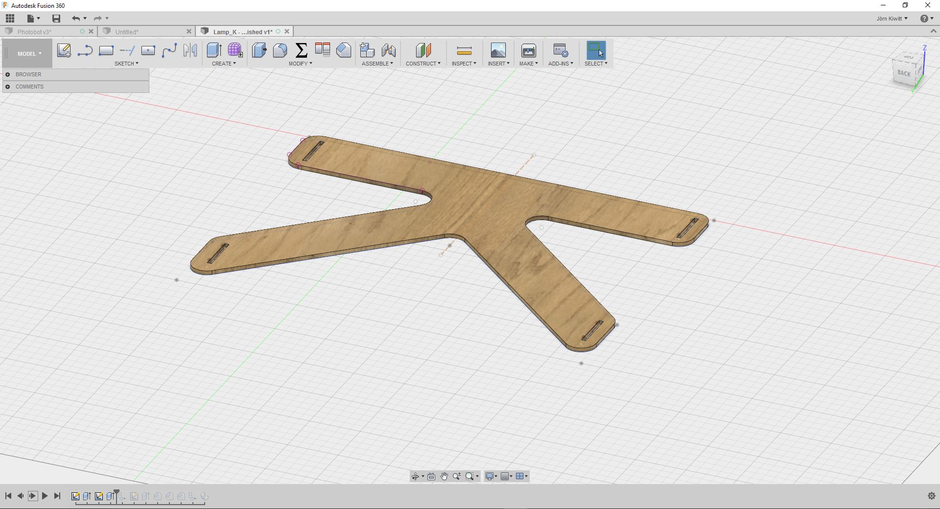
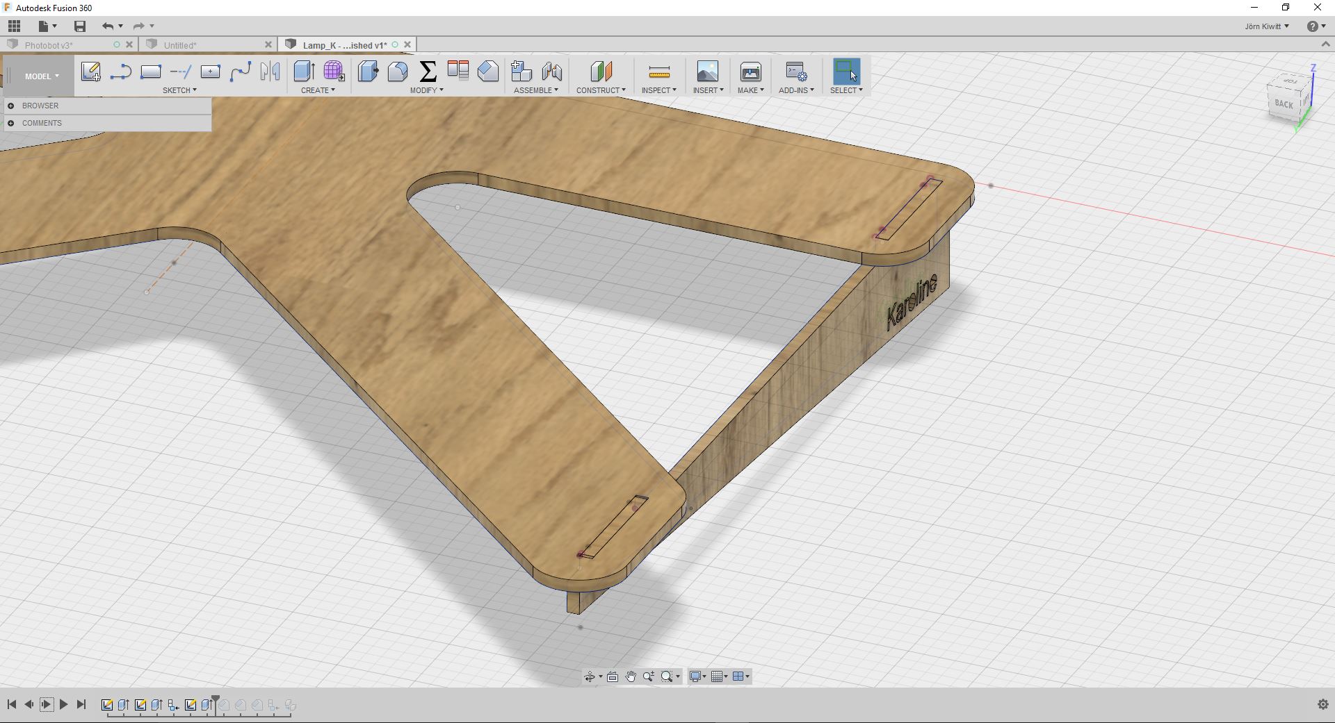
Sketch on plane of the slots to create the profile for the side parts...
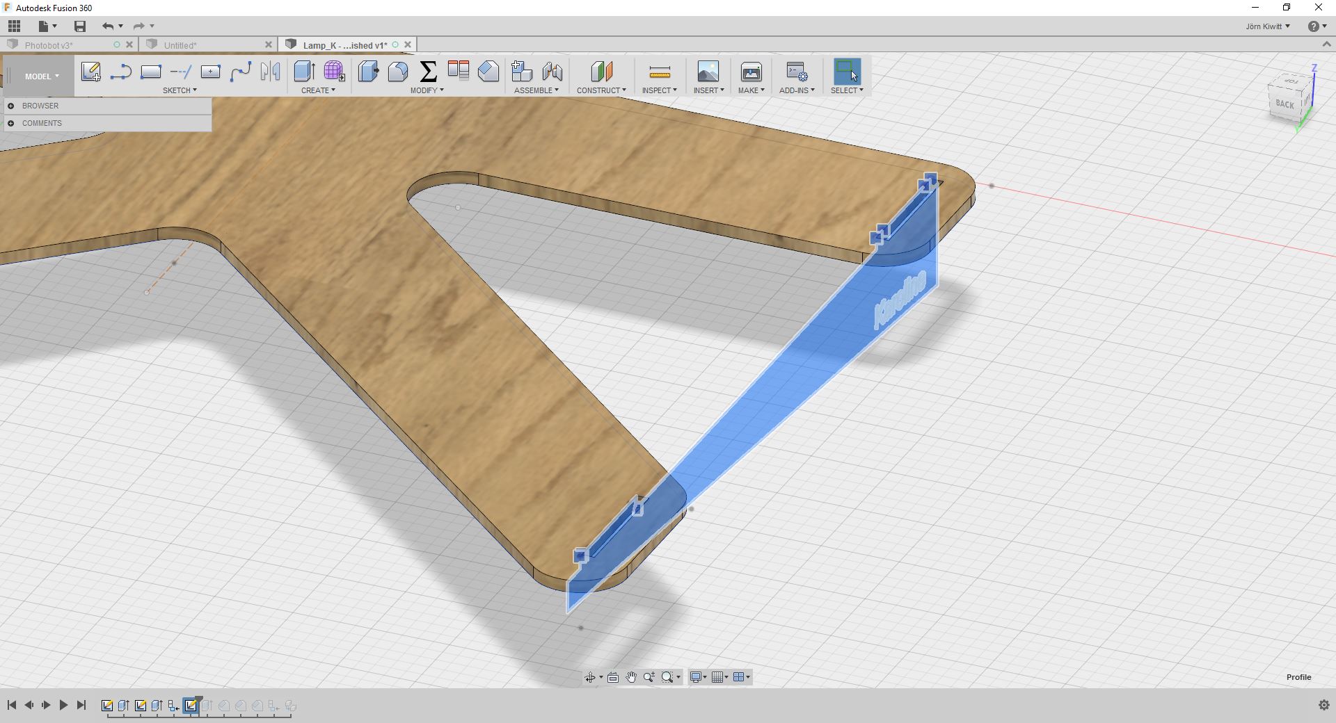
...and extrude it (parameter "MaterialThickness". I also added some fillets to make the fitting easier (not displayed).
Laying your parts flat and move them next to each other. Best is to create a new component and copy the parts into the new component. Afterwards you can align them to a given surface (use the align tool.

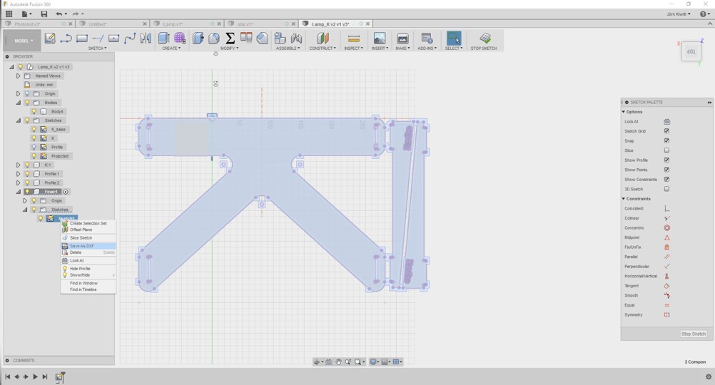
Create a new sketch and project all components onto that sketch.
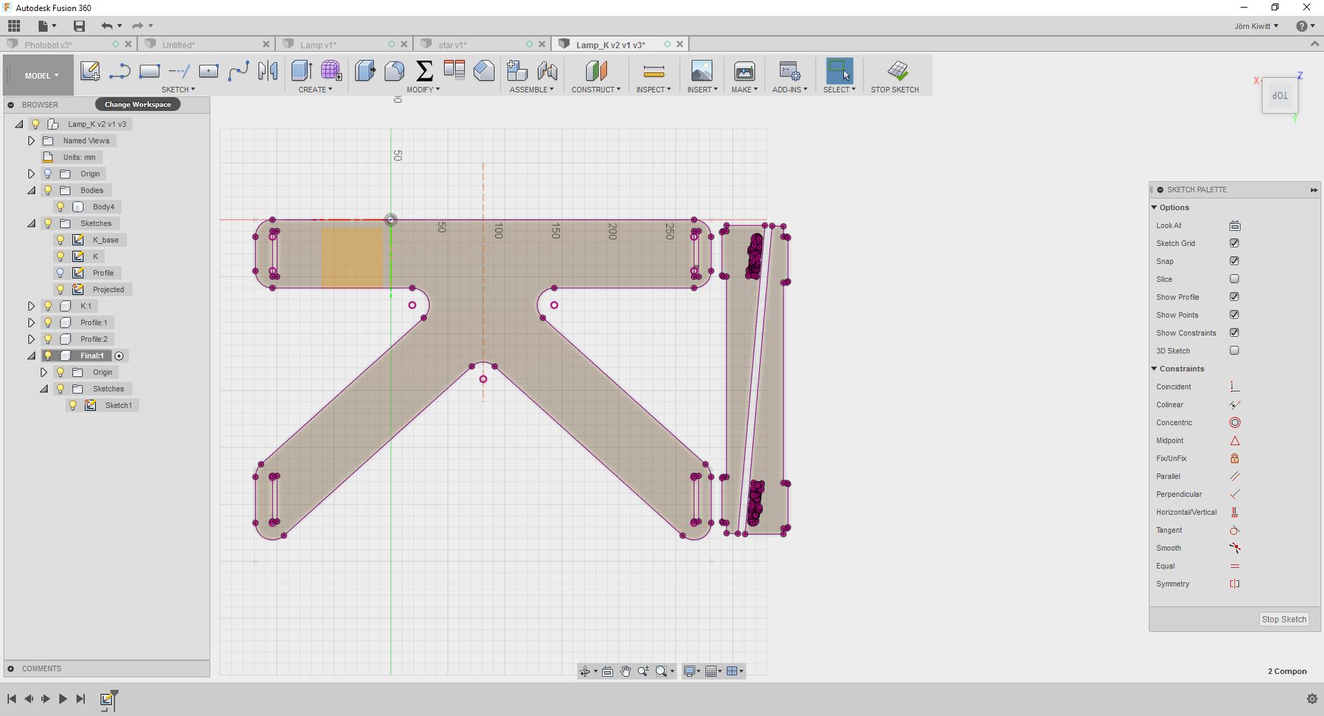
This sketch can then be exported as a dxf-file.
I'll do final adjustments for the laser cutter Inkscape.
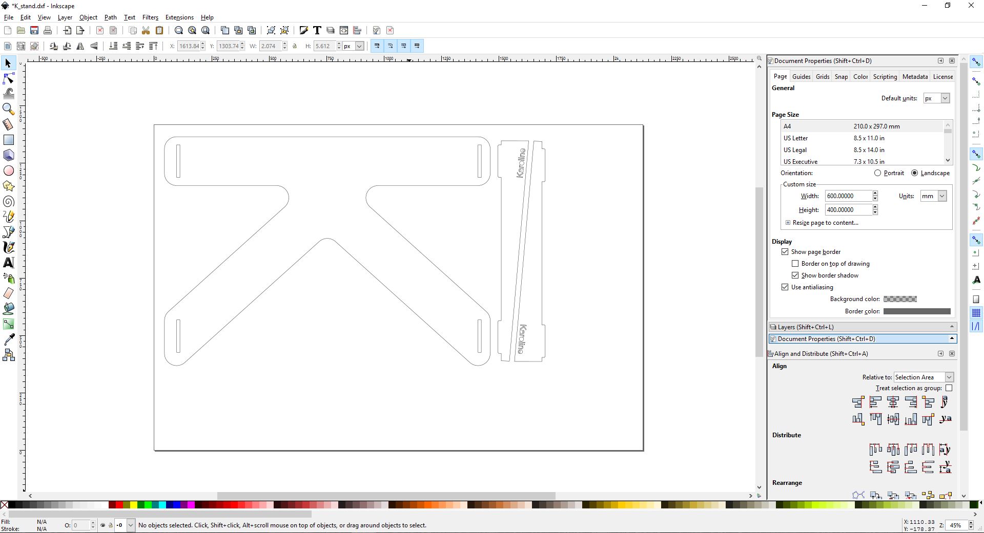
I had to do some bug fixing as the text from Fusion 360 was torn into different segments. I deleted it and added it within Inkscape in order to make it a raster item.
I made some final adjustments adding raster graphics. The inner structures' stroke style gets a green color and is cut first, outer structures second in red.

Settings for the laser cutter
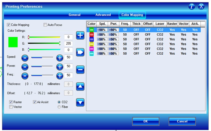
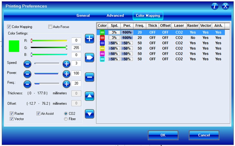
As I am using Inkscape to talk to the laser cutter, I have to do engraving and cutting in two steps in serial. I'll do the engraving first, using the settings depicted on the left hand side and the cutting afterwards at lower speed, depicted on the right hand side.
Finished K stand
The fit with this slot size was very tight. I made a 6 mm slot. The assemble was performed with a hammer.


Tutorial: Laser cutting workflow for Fusion 360
Please find some YouTube videos on the design and the CAM preparing for laser cutting in the videos embedded below, if my explanations were unclear.
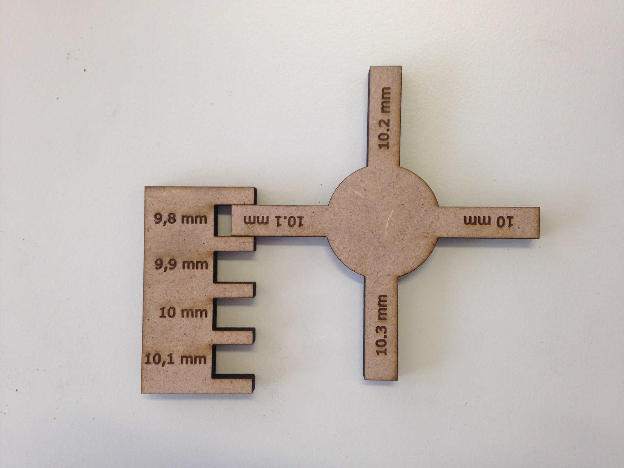
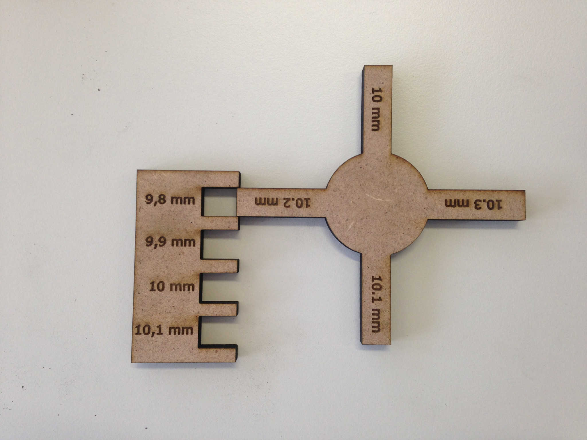
Group assignment: kerf
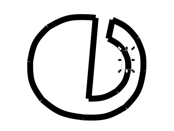
To also use a different CAD program, I used Inkscape to design this part.
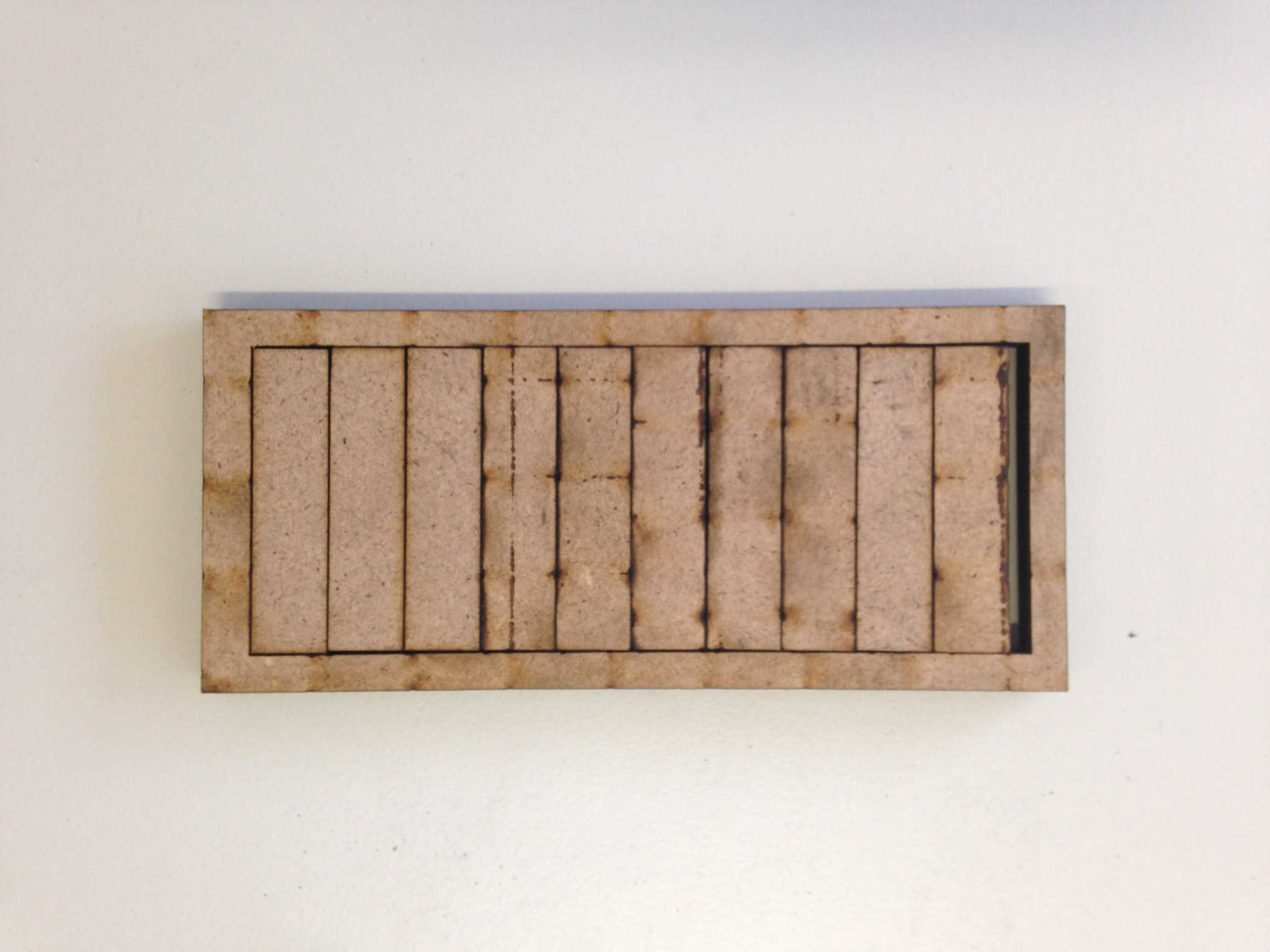
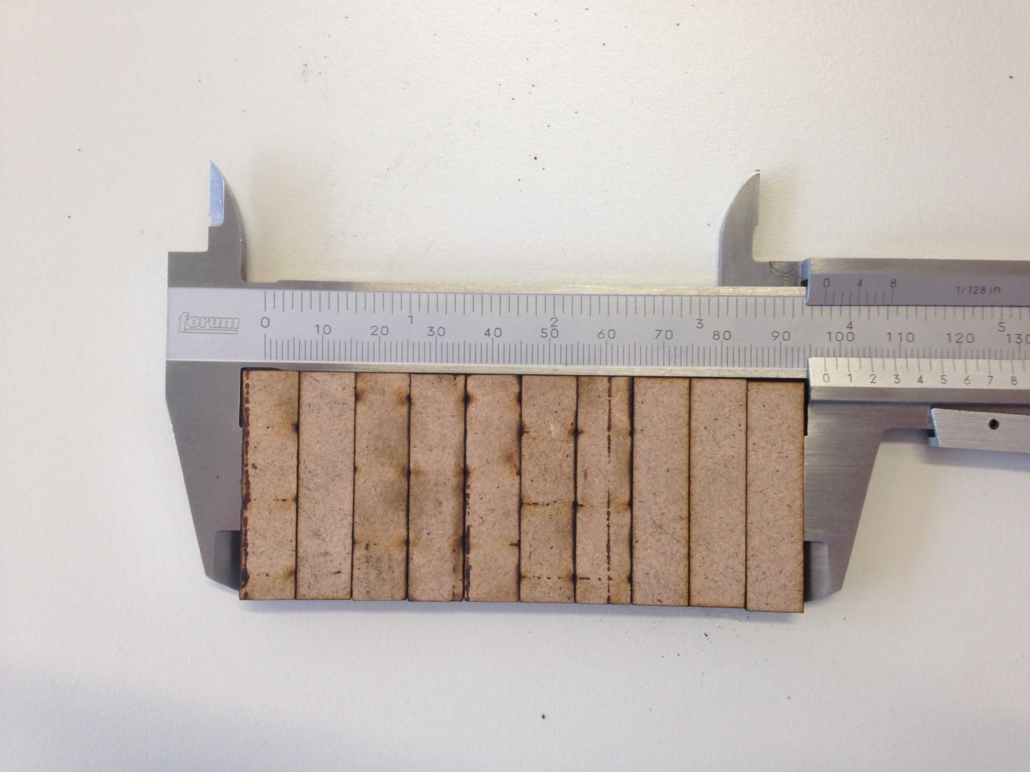
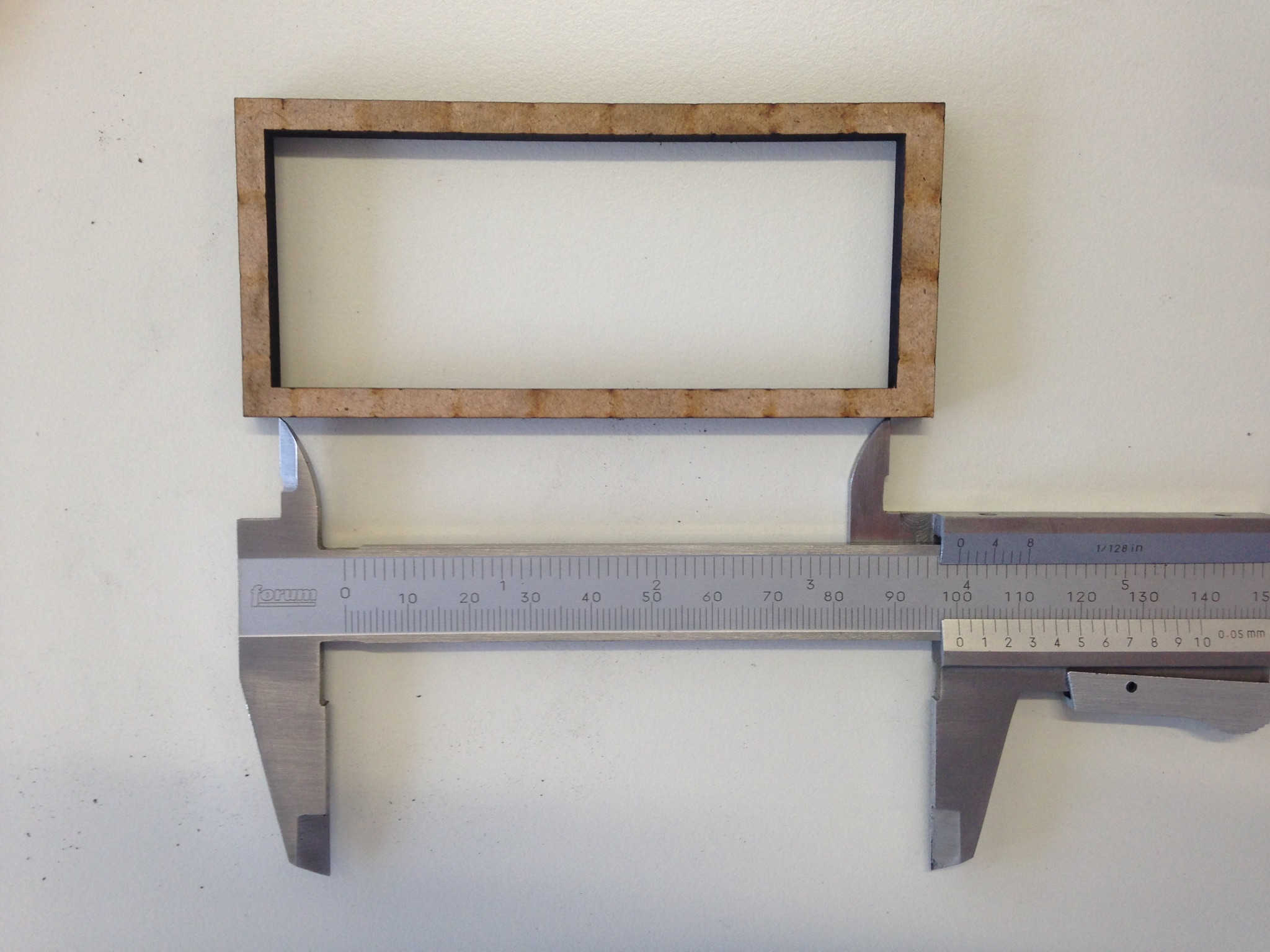
The kerf can now be calculated for 6 mm MDF. I used the same settings as for the cutting of the K stand, i. e. power: 100 % , speed 3 %, frequency 20 %. The overall kerf is 3.5 mm, cutting 10 segments (so 11 cuts). This takes into consideration statistical effects. Therefore the overall kerfs has to be divided by 11. This results in a kerf of 0.0312 mm for this particular material.
