This week we worked all together as a team, trying to make all the mission objectives in time.
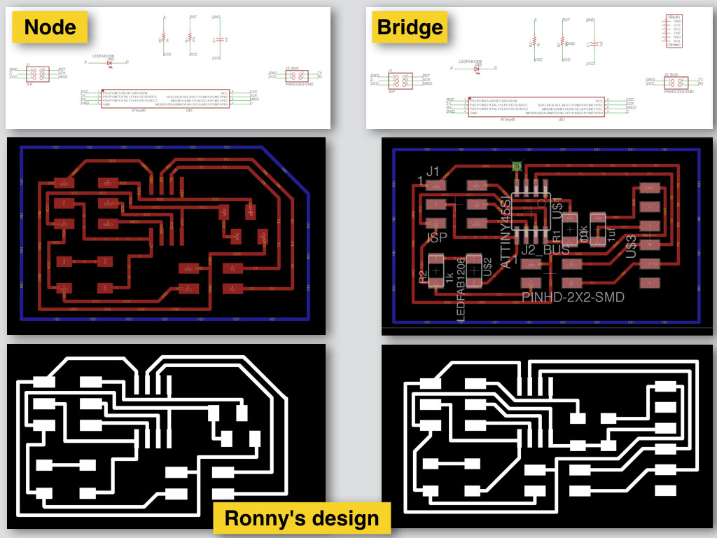
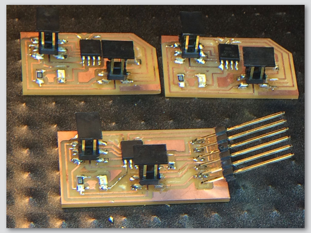
We redesigned the boards thad should communicate and have some hierarchy between them. There will be master/Bridge and slave/Node relationship between them. The Bridge gets the command order and delivers it to the Nodes in right timing.
We based the design of the bridge and the nodes board on Edgar’s design from 2016, Barcelona.
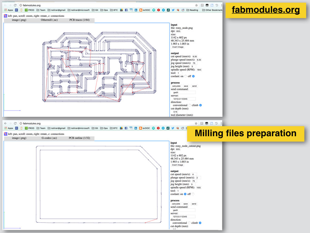
Fabrication:
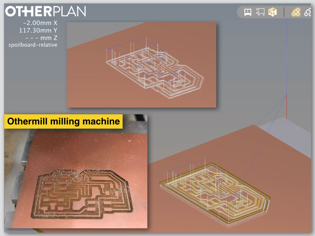
We also created in Adobe Illustrator one png file that included few boards together and sent it to mill to the Othermill machine.
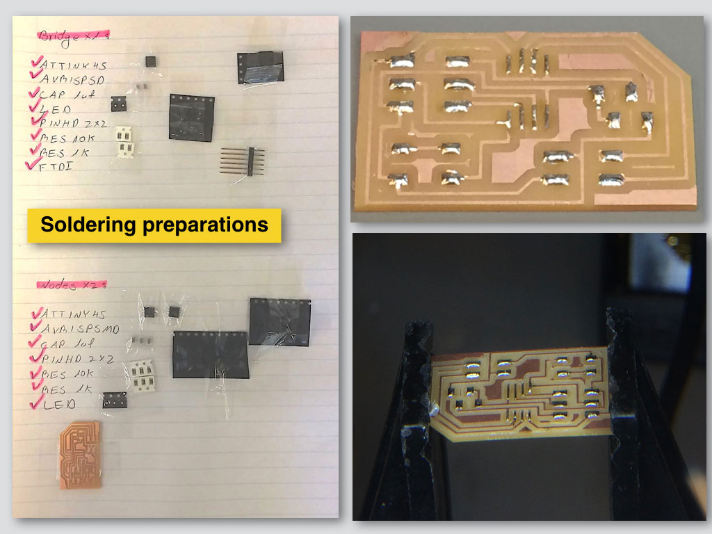
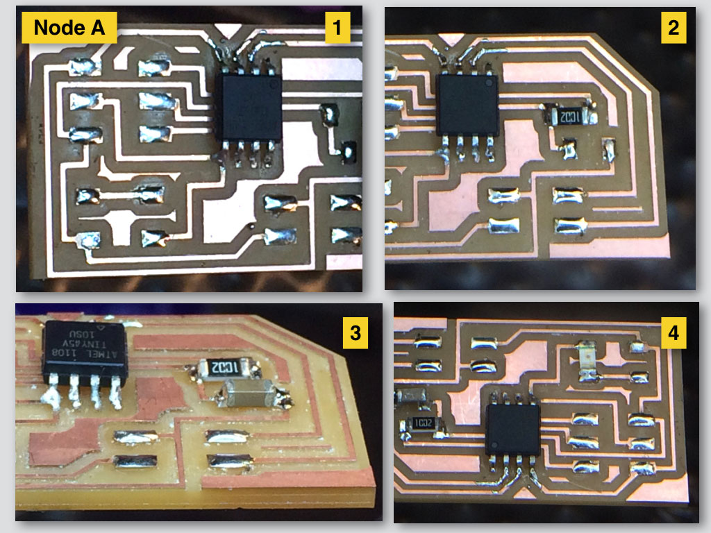
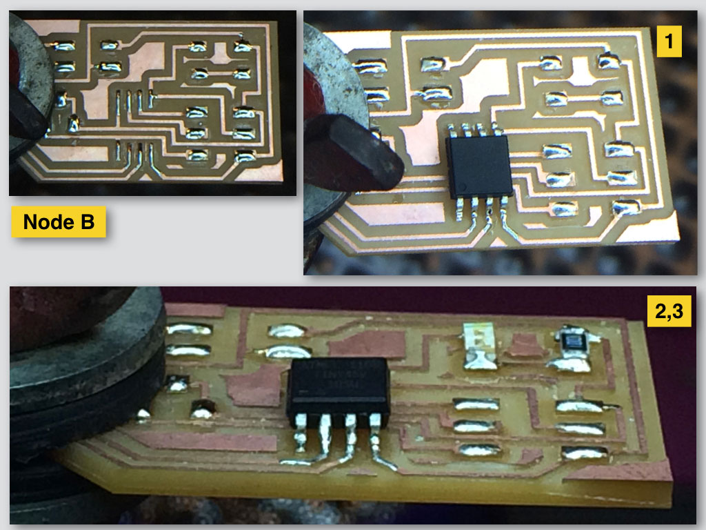
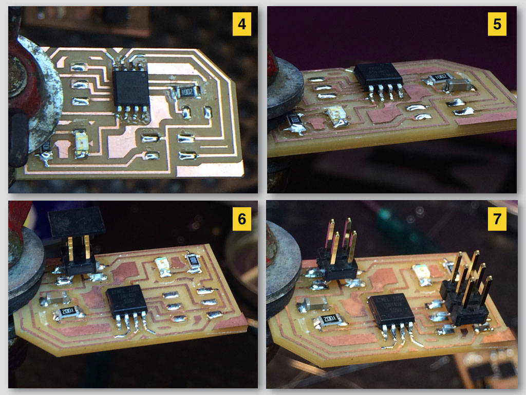
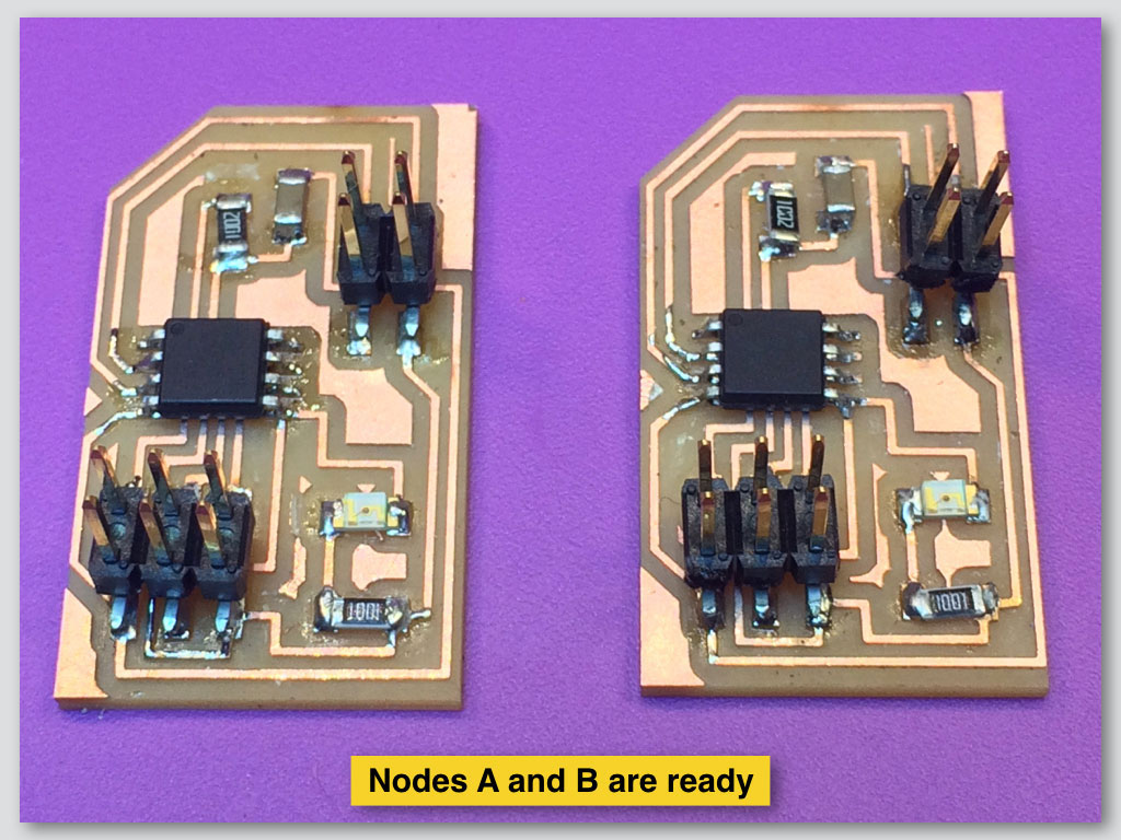
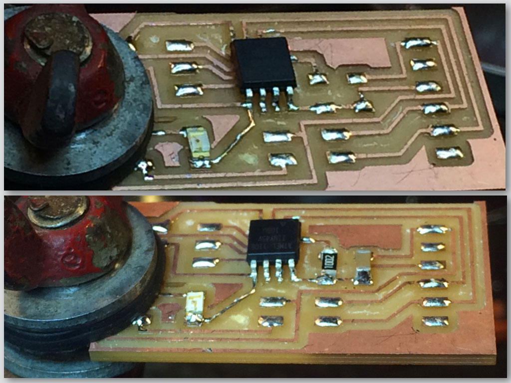
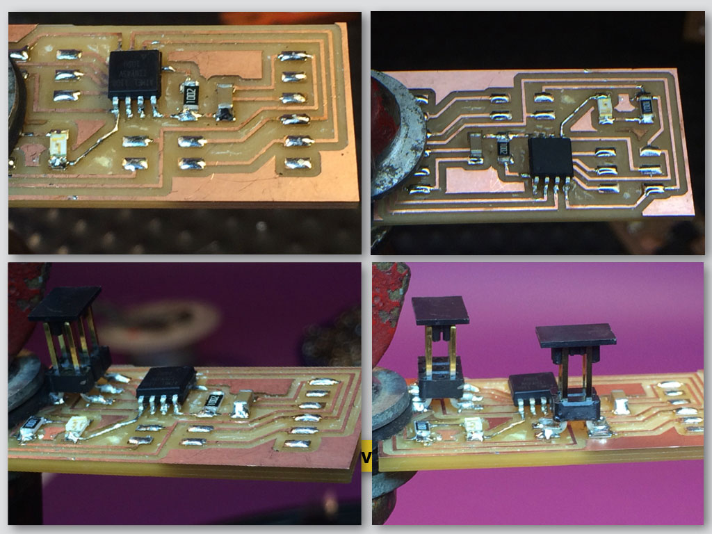
Soldering Node A
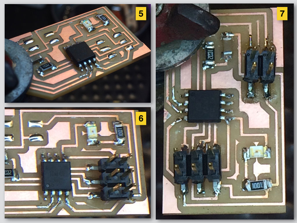
Soldering Node B
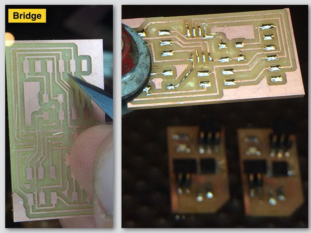
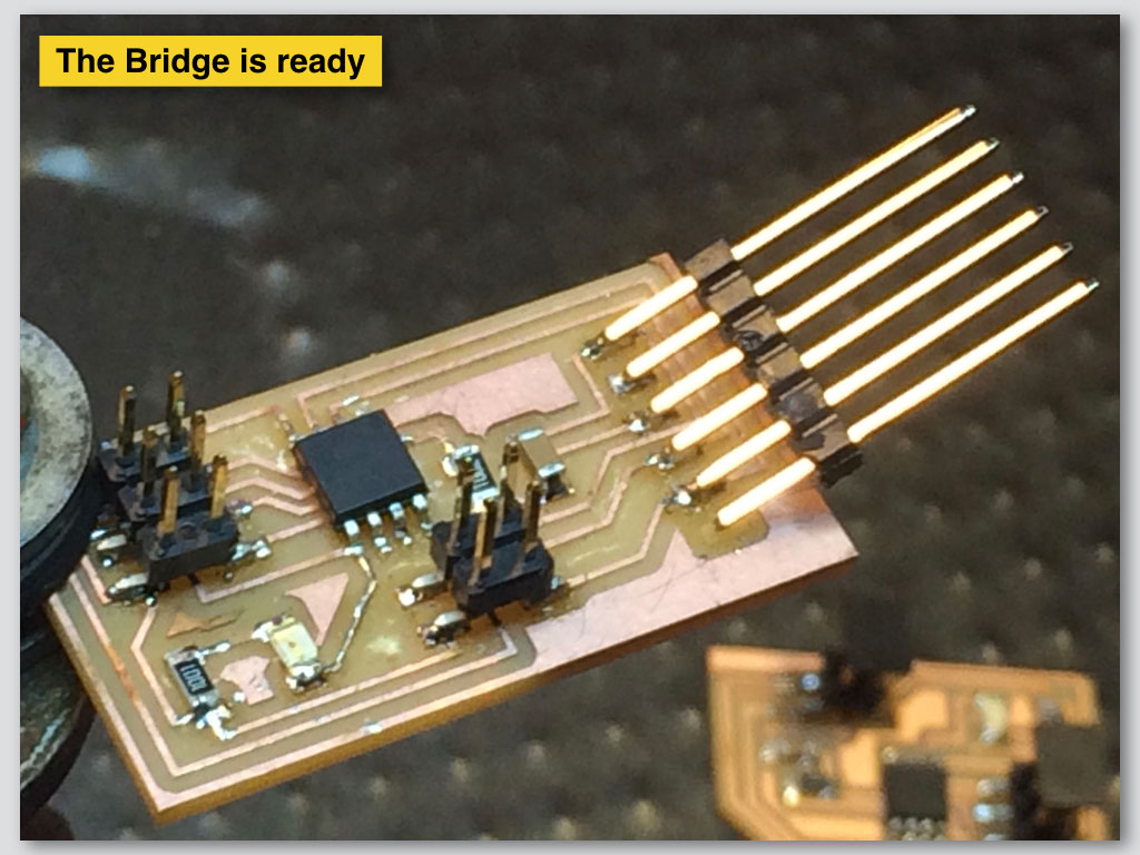
Soldering the Bridge
We checked the boards by Burning Bootloader from Arduino IDE to ensure that the clock cycles match on both boards. Later we programmed the Bridge with its code and the Nodes with separate code and we gave different identification to each Node (#1 and #2). This way the Bridge will send LED blink command separately to each one of the Nodes.
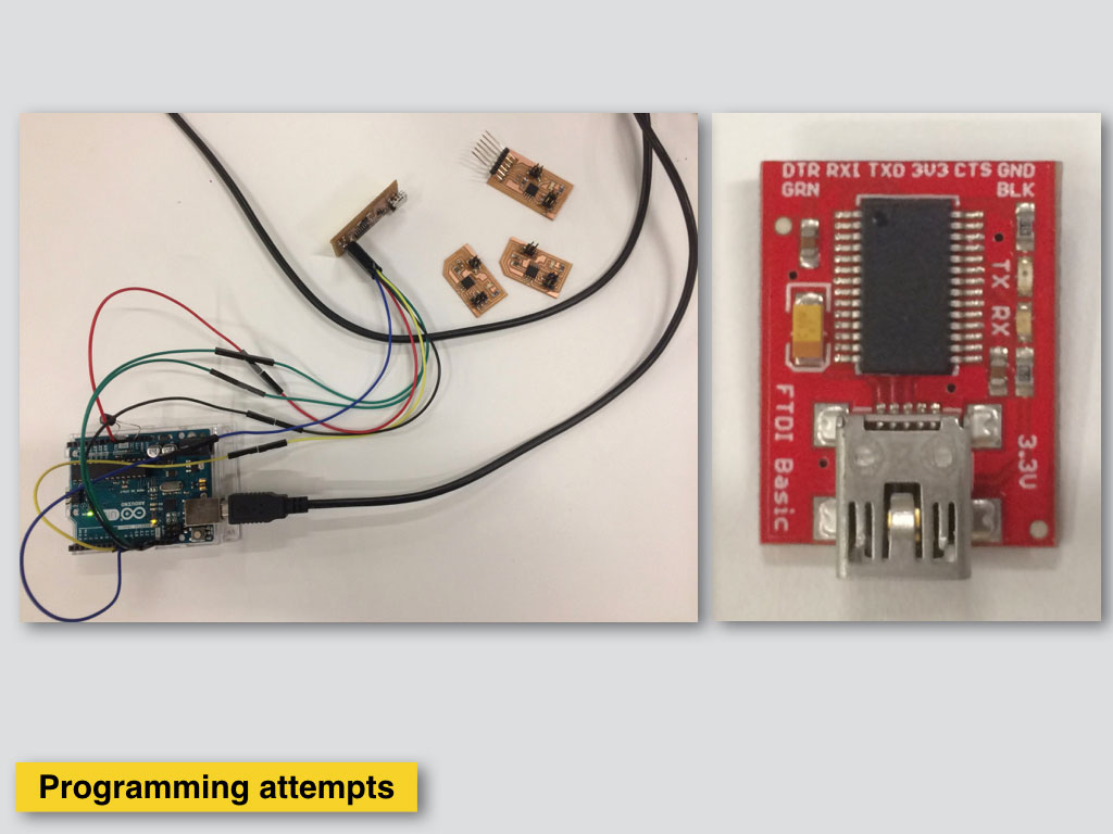
Using USBTiny programer with FTDI as power supply. It looks like there is no power goes out from the programer to the board, only communication.
After uploading the codes on both the circuits, we connected the Bridge circuit to power source using FTDI cable. Connected the Node boards to the power supply of the Bridge board. Since the code was uploaded and power was connected, the Bridge circuit was successful to send the "High" and "Low" signals to the Node circuit.
Then we opened and modified the C code of Node #1 and saved the file. We repeated the steps for programming of Node #2.
Next steps are:
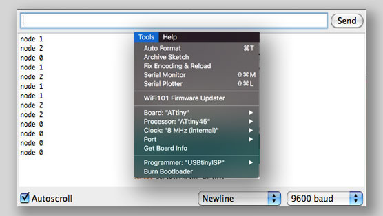
Open Arduino IDE.
Select in Tools menu Board - ATtiny45 with internal 8Mhz clock.
Open the Serial Monitor and selected Baud rate 9600.
Tpyng in one of the Node #id's makes LED in all of 3 boards flashing once and the sellected node flashing next later.
In this example video we print 0 in Serial Monitr window and we have the blink response first from all the boadrs and then blink from the Node #0 which is the Bridge board in our case.