- Measure something: add a sensor to a microcontroller board that you have designed and read it.
Class material: Input Devices
Insper FabLab's operational manual here.
Roland MDX-40A - Machine's tutorial, please click here.
One may also check this tutorial explaining how to mill a coin (and how to operate and setup the working material in a machine like Roland MDX-40A). The manufacture link to its own documentation and information will be found here.
- Autodesk EAGLE
- GIMP2.0
- Roland VPanel for MDX-40A
- Fab Modules
- Arduino IDE
- MS Paint (for PNG images editing)
- FabKit 03 - schematic.
- FabKit 03 - board.
- FabKit 04 - schematic.
- FabKit 04 - board.
- Thermo sensor - schematic.
- Thermo sensor - board.
- Microcontroler final edition - schematic.
- Microcontroler final edition - board.
- Microcontroler PNG image - traces.
- Microcontroler PNG image - cut.
- Extra information and/or files about FabKit 0.3-0.4, please click here.
- SparkFun Ealge libraries.
- Adafruit Eagle libraries.
- Microcontroler traces - rml.
- Microcontroler cut - rml.
- Thermosensor traces - rml.
- Thermosensor cut - rml.
Checking the interaction between devices was helped by the relay actuator. Its files are listed below.
- Relay final edition - schematic.
- Relay final edition - board.
- Relay PNG image - traces.
- Relay PNG image - cut.
- Relay traces - rml.
- Relay cut - rml.
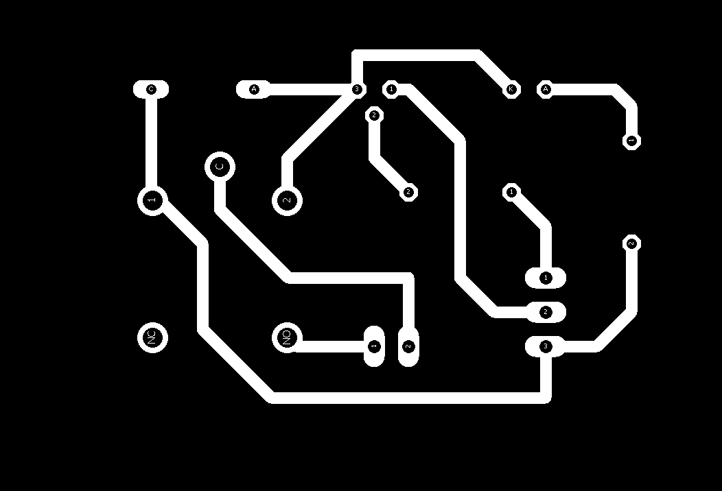
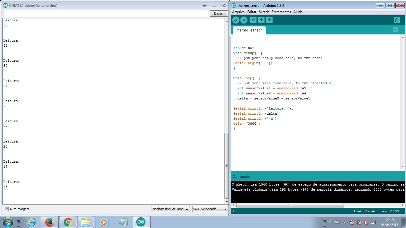
This assignment was a thermosensor issue. I decided to follow the sensor board available in our course documentation, but change the data input control. Instead of building a board with a microcontroler I would have a FabKit04 board to comunicate with the thermosensor and display its measurements over the screen.
This idea of working with another microcontroler board was a strategy to help me out with the final project system. It took me too much time to build the FabKit04 board that worked. Actually, it didn't work properly. In a way to deliver this assignment, I switched the strategy to make a system with an Arduino Uno board and leave the microcontroler board of my own for a later development.
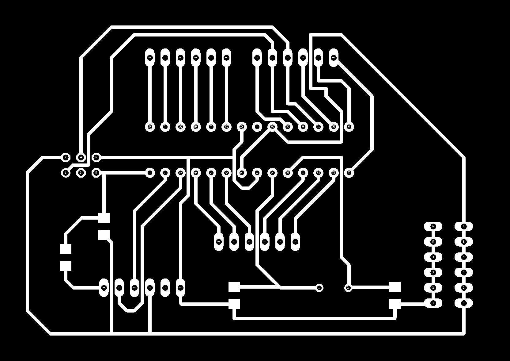
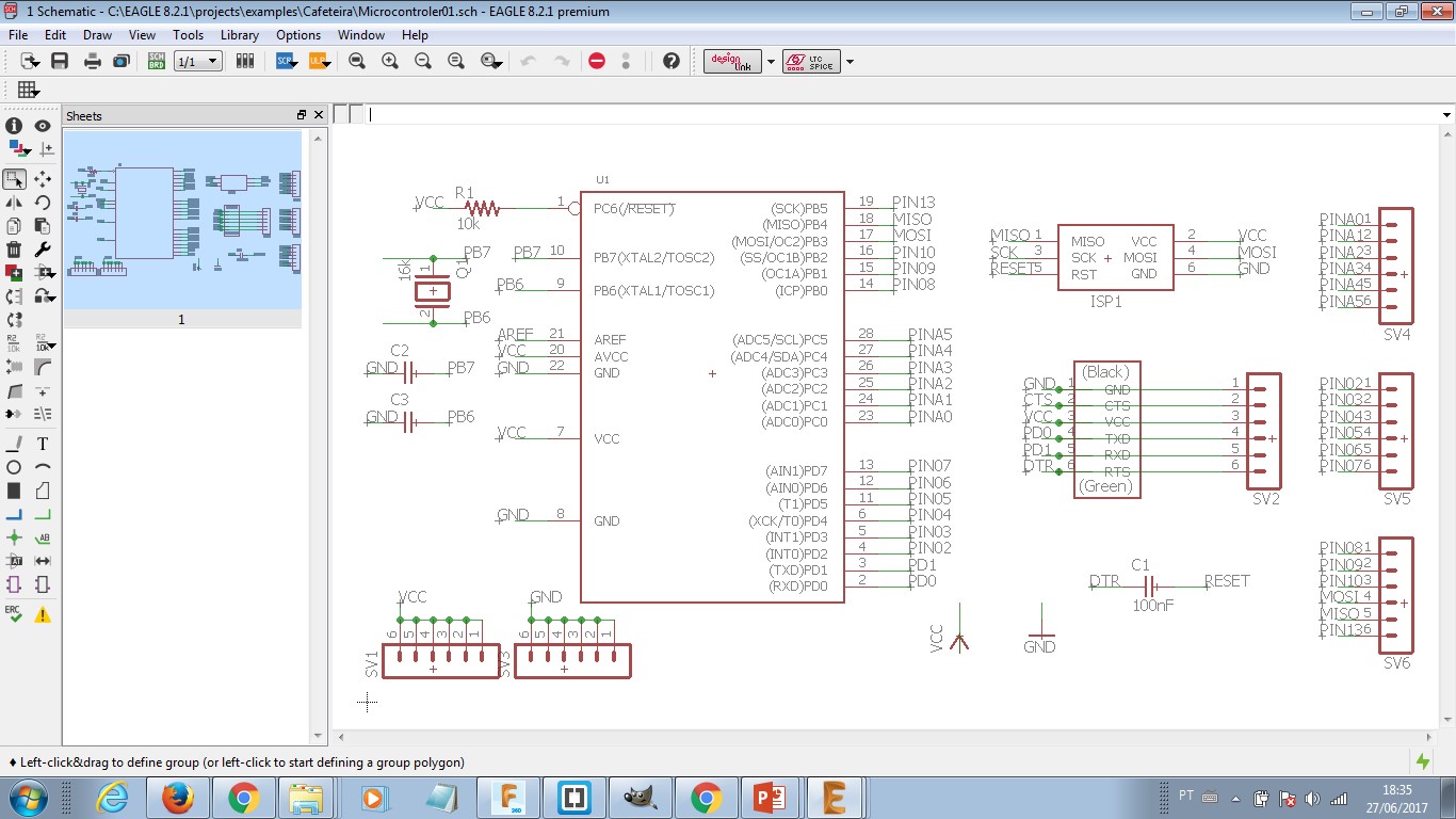
My own microcontroler board will be find below. It was designed after I manage to integrate my final project system. So, it has what it takes for this project (lots of GND and VCC pins). This board presents some problems - it misses a link to reset pin and also another link to SCK pin - that may be corrected in further versions. As I followed standard Arduino IDE programming structure, it was easy to reproduce the same code tested with Arduino Uno in my own board.
| Part | Value | Device | Package | Description | MF | MPN | OC_FARNELL | OC_NEWARK |
| R1 | 10k | R-US_R1206 | R1206 | RESISTOR, American symbol | ||||
| R2 | 10k | R-US_R1206 | R1206 | RESISTOR, American symbol | ||||
| R3 | 10k | R-US_R1206 | R1206 | RESISTOR, American symbol | ||||
| SV1 | MA04-1 | MA04-1 | PIN HEADER | unknown | unknown | |||
| THERMISTOR | 10k | R-US_R1206 | R1206 | RESISTOR, American symbol |
| Part | Value | Device | Package | Description | MF | MPN | OC_FARNELL | OC_NEWARK | PROD_ID | SPICEMODEL | SPICEPREFIX | VALUE |
| C1 | 100nF | C-USC1206 | C1206 | CAPACITOR, American symbol | ||||||||
| C2 | 22pF | C-USC1206 | C1206 | CAPACITOR, American symbol | ||||||||
| C3 | 22pF | C-USC1206 | C1206 | CAPACITOR, American symbol | ||||||||
| Q1 | 16kHz | CRYSTALHC49S | HC49/S | CRYSTAL | 1667008 | unknown | ||||||
| R1 | 10k | RR1206 | R1206 | RESISTOR, European symbol | NONE | R | ||||||
| SV1 | MA06-1 | MA06-1 | PIN HEADER | unknown | unknown | |||||||
| SV2 | MA06-1 | MA06-1 | PIN HEADER | unknown | unknown | |||||||
| SV3 | MA06-1 | MA06-1 | PIN HEADER | unknown | unknown | |||||||
| SV4 | MA06-1 | MA06-1 | PIN HEADER | unknown | unknown | |||||||
| SV5 | MA06-1 | MA06-1 | PIN HEADER | unknown | unknown | |||||||
| SV6 | MA06-1 | MA06-1 | PIN HEADER | unknown | unknown | |||||||
| SV7 | MA03-2 | MA03-2 | PIN HEADER | unknown | unknown | |||||||
| U1 | 328P | ATMEGA328P_PDIP | DIP28 | Atmel 328P | IC-09136 | 328P |
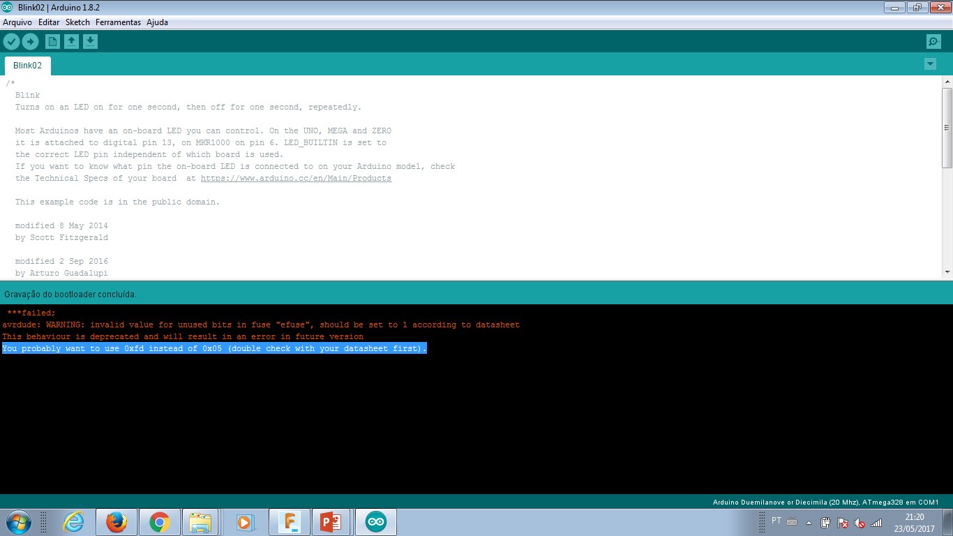
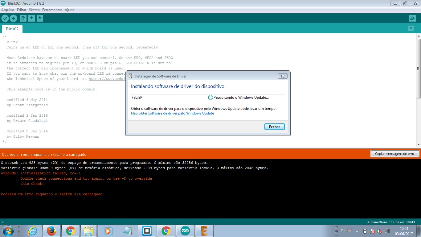
Programming the microcontroler boards - either Fabkit04 or the one I made - was something that needed extra attention. Each hardware has a library that indicates how one communicates to another. Learning about it is checking documentation or talking to someone who had a similar problem before. In this sense, working with a group (or network) where one can discuss about problems, helps with debugging. Some problems were library related; it means I had to download and install these libraries in order to make the project work properly.
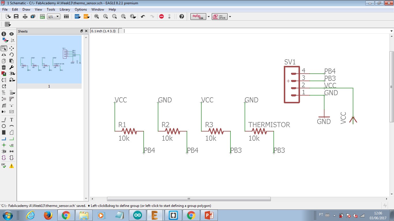
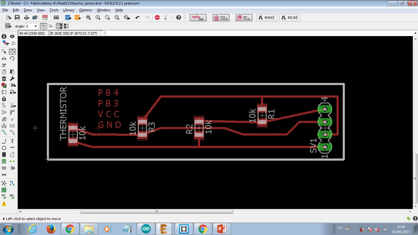
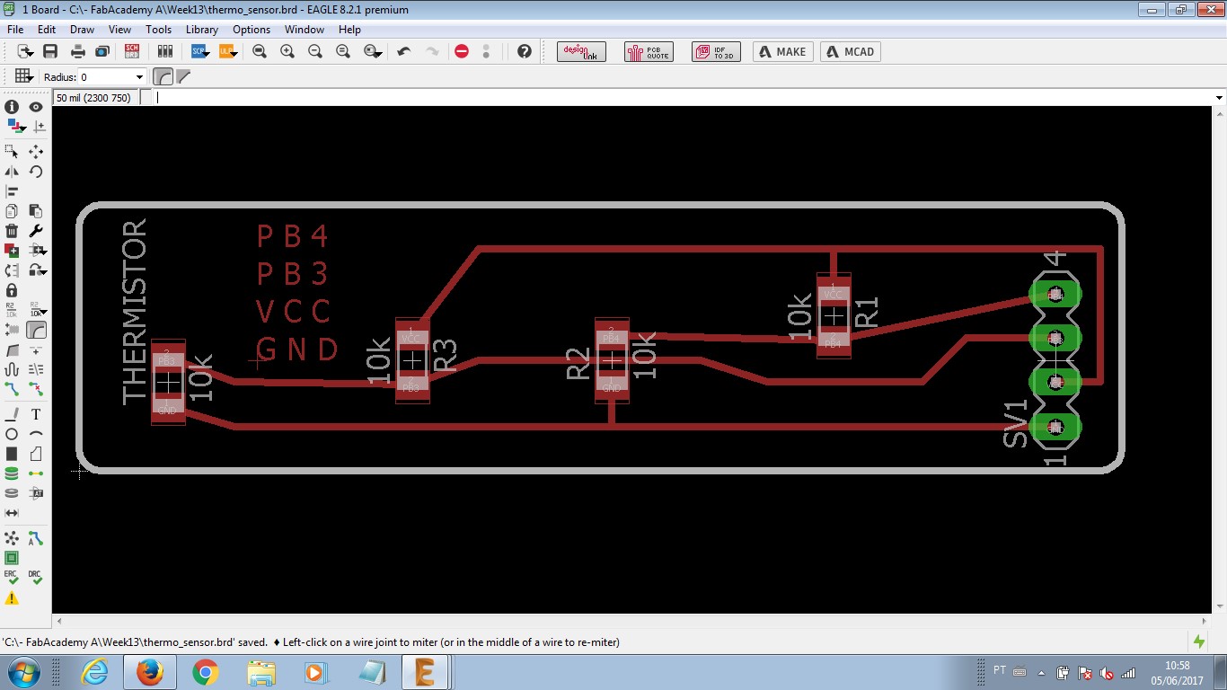
Thermosensor board was chose as input device. I re-wrote the resistors schematic. I tryed to find a component in an Eagle library that described Thermistor NTC, but I had no success with a smd component. After a while, I applied a fourth resistor into my schematic and labled it as a thermistor. It worked properly, once its packaging is the same. Note: packaging is the design/description of a component dimension in real world. This data builds the design block for a component be represented in a board sketch. If the packaging is incorrect, the design of traces, pads and vias is wrong or it doesn't match the components real size. A good PCB has its design properly describing components packaging.
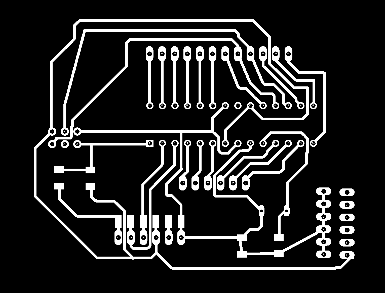
As I had several problems with SMD components soldering process. The soldering material available needed temperatures above 380 degrees Celsius and it seems these high temperatures were damadging the components. The thermosensor, for instance, has 265°C as max soldering temperature as sais datasheet information. I chose to build a microcontroler board with PTH sized Atmega328. It follows Eagle's schematic and board design, images to FabModules CAM (that I used the same setup from preveious boards), and photos of my final result.


small.jpg)
small.jpg)
It follows the programms that were develop in order to read temperature and react to it based on a microcontroler board.
- Code based on ArduinoIDE for thermosensor reading.
- Code based on Processing for thermosensor reading.
- Code based on ArduinoIDE for the final project. It includes thermosensor reading thermocouple MAX6675 (manufactured), keyboard reading, display output, relay output.
- Arduino Libraries.
-----------

This work is licensed under a Creative Commons Attribution-ShareAlike 4.0 International License.