Input Devices
Tested
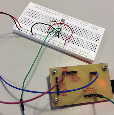
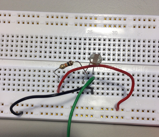
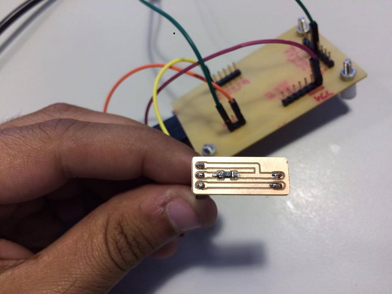
To read the sensor i use the board i make. I use one ligth Sensor. I connect the sensor with a 10k resistance a analog pin. In this image can see the way i connect the sensor to the board. This sensor is 5V sensor. This is the method i use to test the photoresistor.
In this video can see i open the serial port of arduino Ide to see the values that sensor gives me.
The code i use for read this values is after the setup i put the pin i connect the sensor in my case i use the analog pin 0 and i create a variable with value 0.
In setup i open the serial.
In the loop i put the variable equal to the analog read and print the value in the serial port.
Design
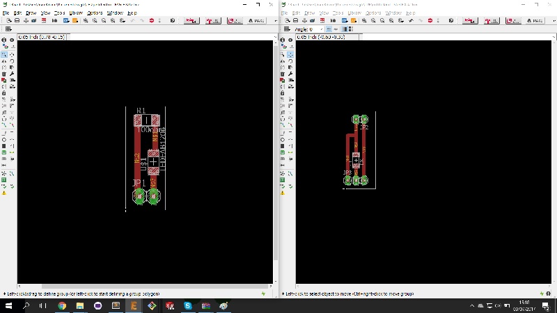
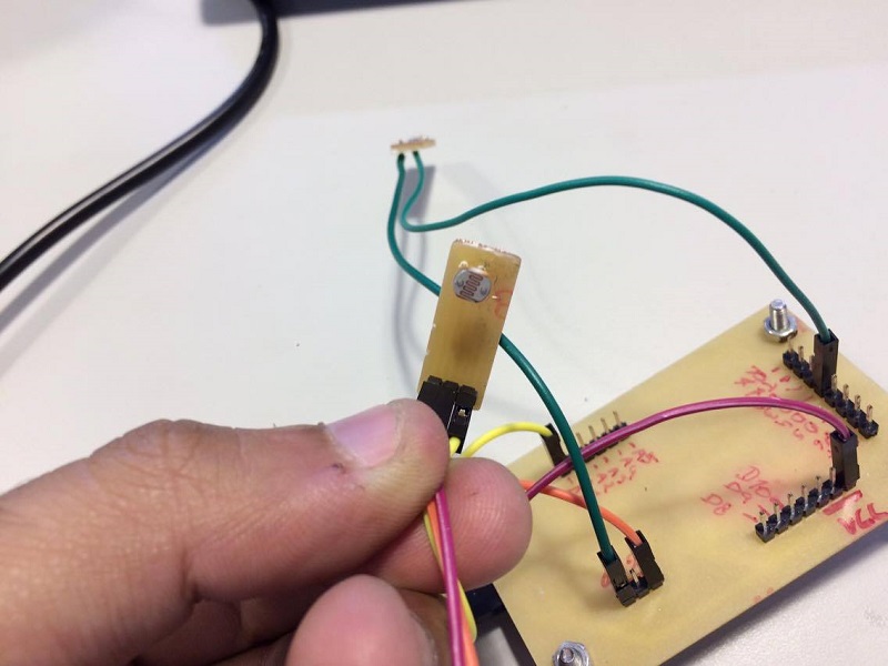
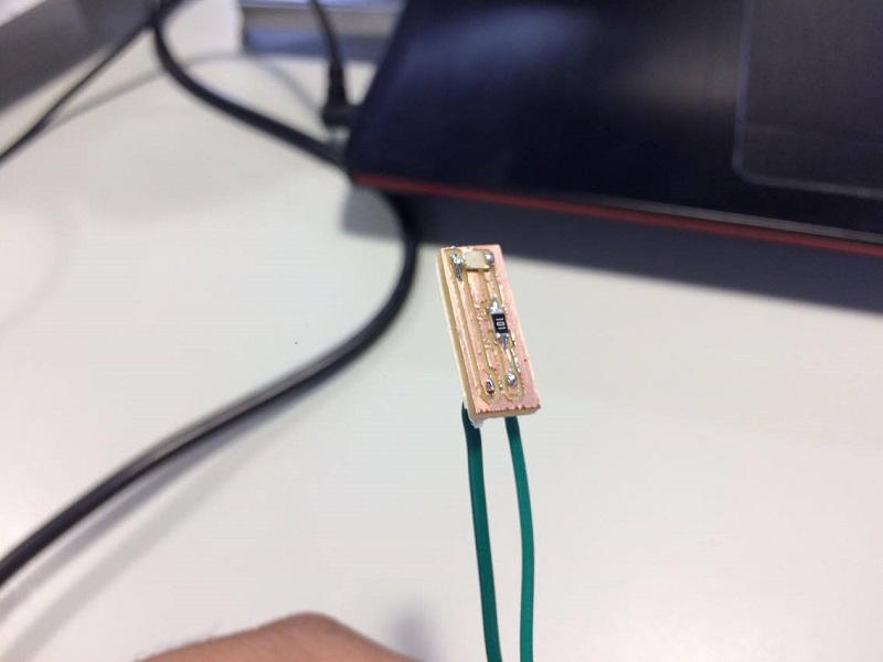
After i test the sensor i design two board one to put the photoresistor and the other is one led.
Programming
After i machining the boards and soldering i program the microcontroller with this code if the sensor value more of 700 the led go on if not the the led go off. This values can changes because the ambient light.This is the final result.
All in one board
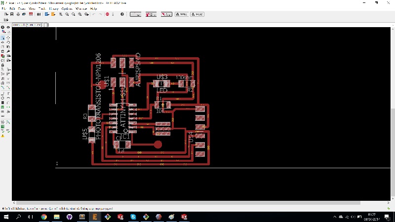
After i make the all test i design one board with the attiny44 and ligth sensor and led.
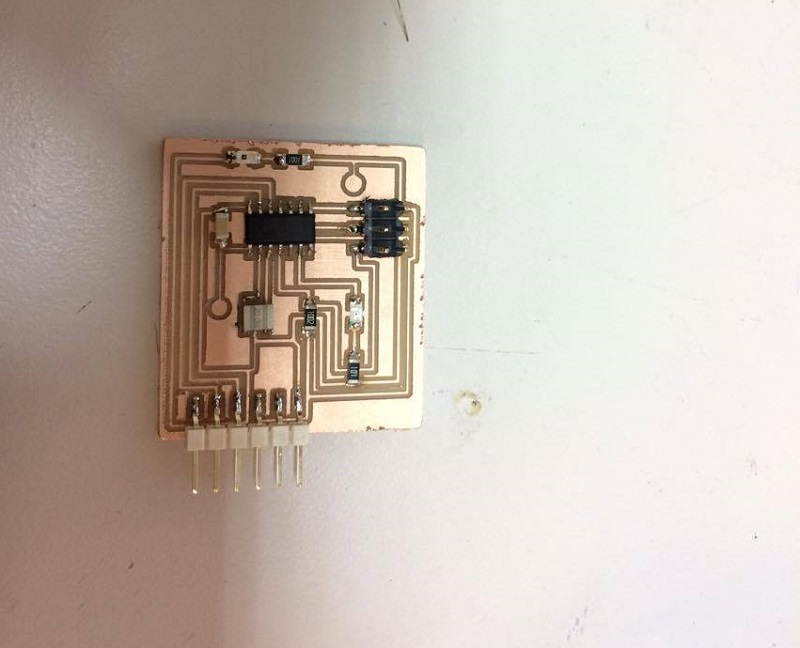
For programing i use the same code but i change the pin the led is in the pin 7 and the light sensor in pin 3 and dont use the serial.