Output Devices
Read Data Sheet
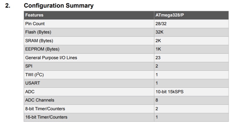
Before i Design the board i read the datasheet of microcontroller.
The operating voltage ir 1.8V - 5.5V and the speed grade for the 4MHz 1.8-5.5V to 10MHz 2.7 - 5.5V to 20MHz 4.5 - 5.5V.
 And this is the pinout for my package component.
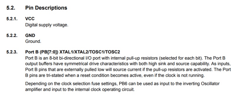
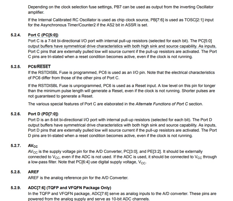
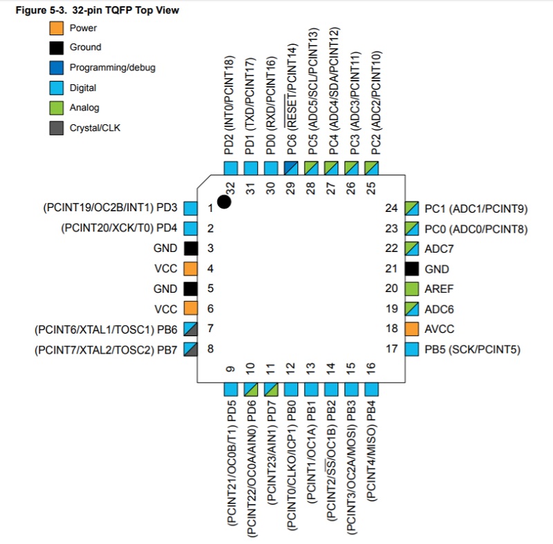 And i got this information from pins.
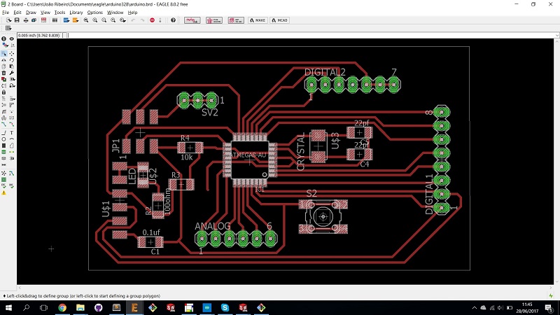
Design
To this week i decide to control a motor stepper.
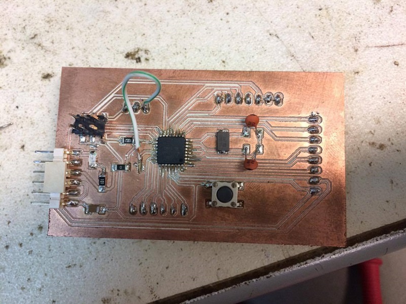
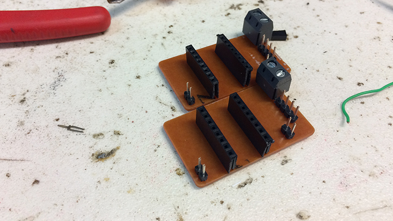
To control the stepper i design a board with a Atmega328.
 I use this wire to pass the gnd.
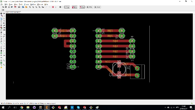
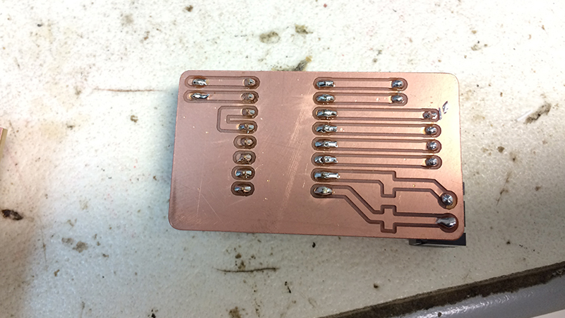
 Also i design a pcb to put the Driver stepper.
I use the Driver drv8880 to control the stepper.
Also i design a pcb to put the Driver stepper.
I use the Driver drv8880 to control the stepper.
Connect
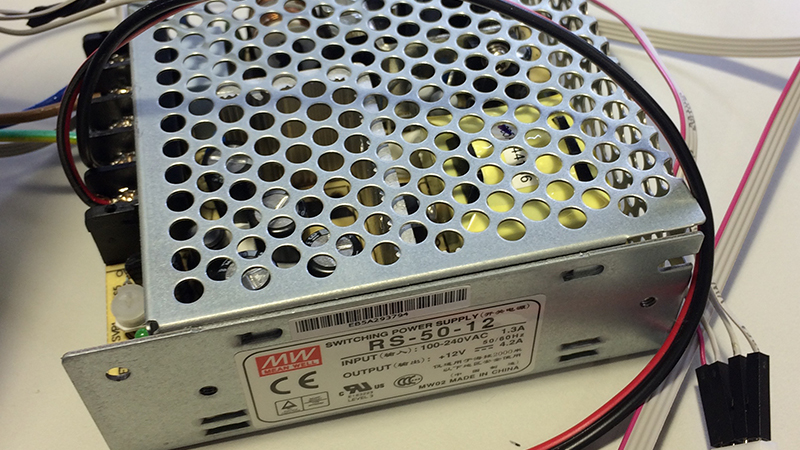
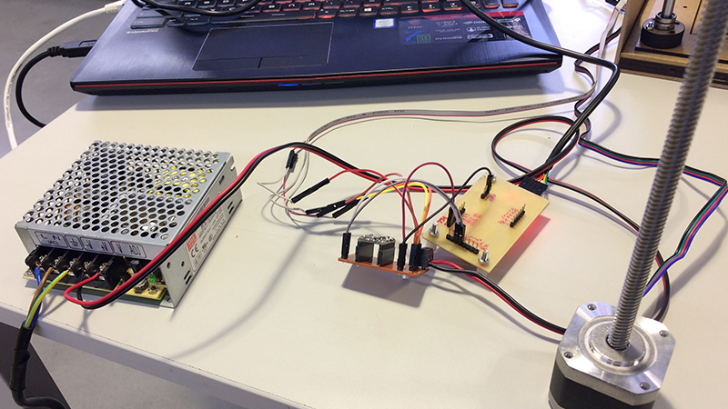
To control the stepper i connect the driver to my main board I connect the pin steps and the direction to the Digital pins of my board. I use on power supply 12V to power the stepper.
And my main board give power to the driver. To connect the stepper i connect four pins in driver.
Programming
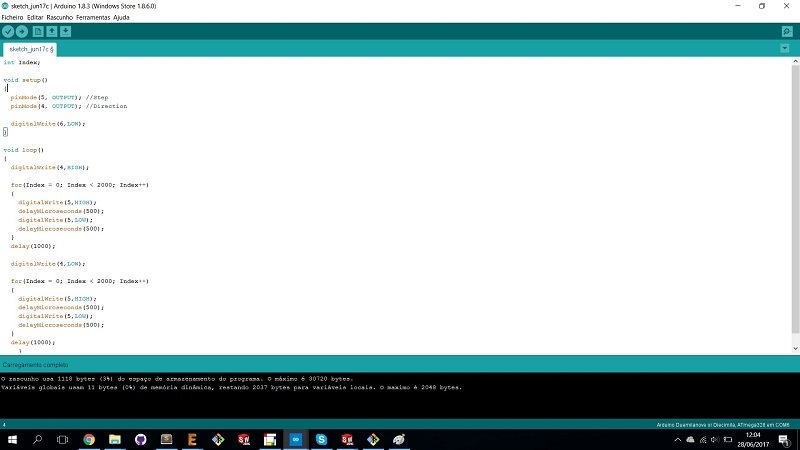
After connect all pins and power i use the simple sketch to move the stepper for one direction and after move the other side. In the code i write in steup i said the pin 5 and 4 is output. In loop i write the pin digital 4 is High this pins is the direction if is low the stepper move to one direction if is high the stepper move to the other side. After i write for an for is a repetition control structure that allows you to efficiently write a loop that needs to execute a specific number of times in my case i sau repeat 2000 times and go to add.
And in this video you can see the final result.
Test Code
After i control the motor stepper i make another code for control the stepper but this time i use two buttons. The funcionality of the buttons is if click one the button the motor stepper move to left if click the other button the motor stepper moe to the other side.