Embeeded Programming
For this assigment, we have to:
- (DONE) Read a microcontroller data sheet.
- (DONE) Program your board to do something, with as many different programming languages and programming environments as possible.
- Optionally, experiment with other architectures
All the files created for this assigment can be found on the link bellow:
---> DOWNLOAD FILES<---
Have you:
- Documented what you learned from reading a microcontroller datasheet?
--> yes
- Specified what questions do you have? What would you like to learn more about?
--> yes
- Programmed your board?
--> yes
- Described the programming process/es you used?
--> yes
- Included your code?
--> yes
Choosing a Board
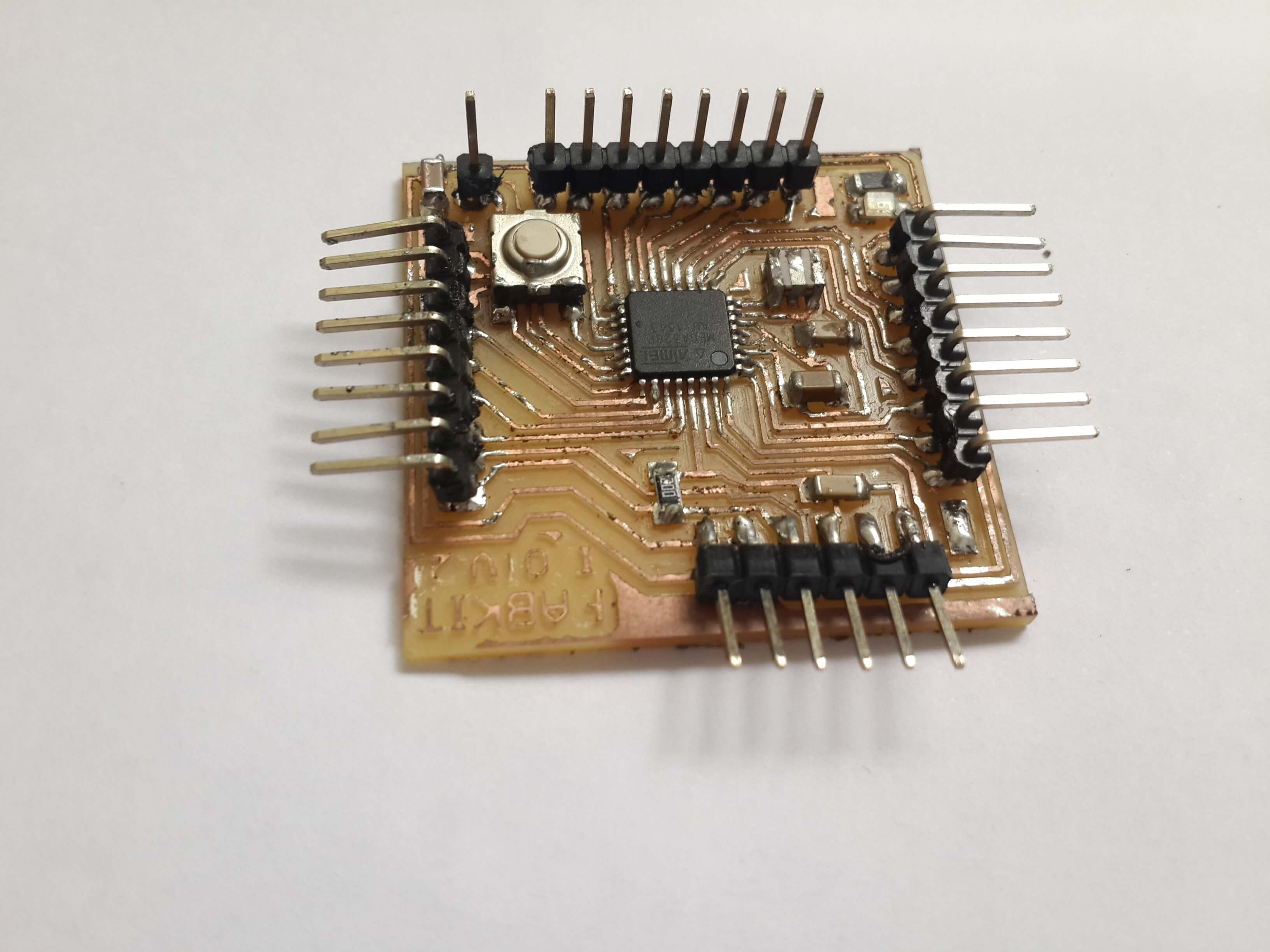
For this assigment I wanted to control a 7 segment display from the PC, so at least I needed 7 digital output pins for the seven segments that represent the number, one extra pin for segment that represents the point and a couple of digital pins for serial communication. In total, 10 digital pins.In my 6th assigment, I made a board, which had available only 5 digital output pins (The MISO, MOSI and SCK pins from the AVR-ISP port and the Tx and Rx pins for the FTDI cable). So, if I wanted to control the 7 segment display, I had to mill another board which had at least 10 digital output pins. In this case, I chose to mill a Fabduino V 2.0. Since, It has 18 digital pins available (6 digital pins from port B, 6 from port C and 6 from port D).
Microcontroller Datasheet
Electrical Characteristics
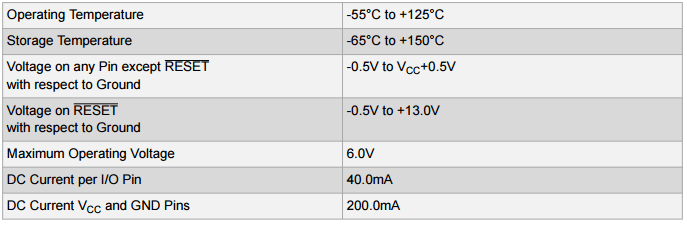
Before using any kind of chipset, we must read the electrical characteristics section on its datasheet, so that we can avoid that the chipset get burned accidentally.
Some basic parameters we must look for in a datasheet are the maximum and minimum power source voltage, the maximum curent that can be obtained from its output pins and the maximum current that the chipset can give summing the current from all its output pins. If one of this limits values is exceeded on the chipset, it will get burned
On the Atmega 328p this parameters are specified in Absolute Maximum Ratings and its corresponding values are 6 V ,40 mA and 200 mA respectively
Internal Components
The internal components of the chipset are usuallly specified on a section called "Block Diagram". The image below shows all the Atmega 328p internal components.
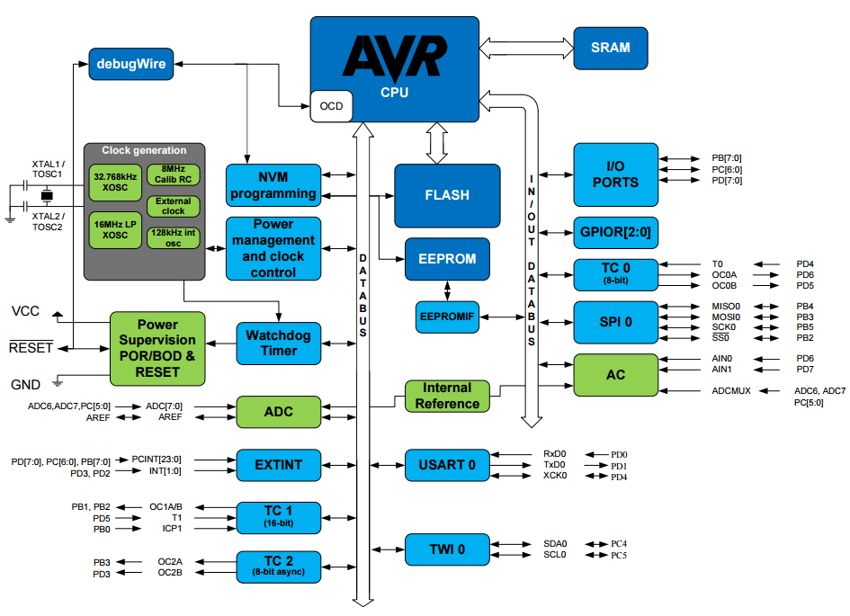
We can see from the image that this microcontroller has 3 main memories, which are the SRAM, the Flash and the EEPROM. The SRAM is the fastes of the three, thus it stores all the variables used in our program in some of its 32x8 bit general purpouse registers; the flash memory, which is the second fastest, stores the line codes of the program and can be used to store not frequently used variables; while the EEPROM, which has a limited number of writings, is used for storing constants that are not going to be changed almost never.
Comunication:
The Atmega 328p can communicate with other devices by serial communication (this means that the data is transmitted in a serial way by its comuncation interfaces). This Microontroller has an internal USART, which is a piece of hardawre wich can comunicate by sending TTL signals, and it also counts with internal SPI and TWI modules which permit it to comunicate in SPI and I2C protocol respectively.
Making the Circuit
I used the milling machine Modela MDX-20 for making my circuit, in this case, I used the circuit design of the fabkit v2 version, which can be founded here. All the necesary steps for working with this machine are explained here
.
Programming the Microcontroller
This microncontroller can be programmed in serial mode by its ISP (ICSP) port. And it can be programmed in different IDES and languages. However, it can not be programmed in all the available languages, since most of the available programming languages have been developped for modern computers wich have a 32 bit or 64 bit architectures, while this microcontroller has an 8 bit architecture and needs a compiler of a language for that architecture. This microcontroller is usually programmed in C or assembler (machine code) but can be programmed in other old programming languages which were developped originally for 8 bit architectures like Basic and Forth and can also be programmed in reduced variations of more modern languages like python.
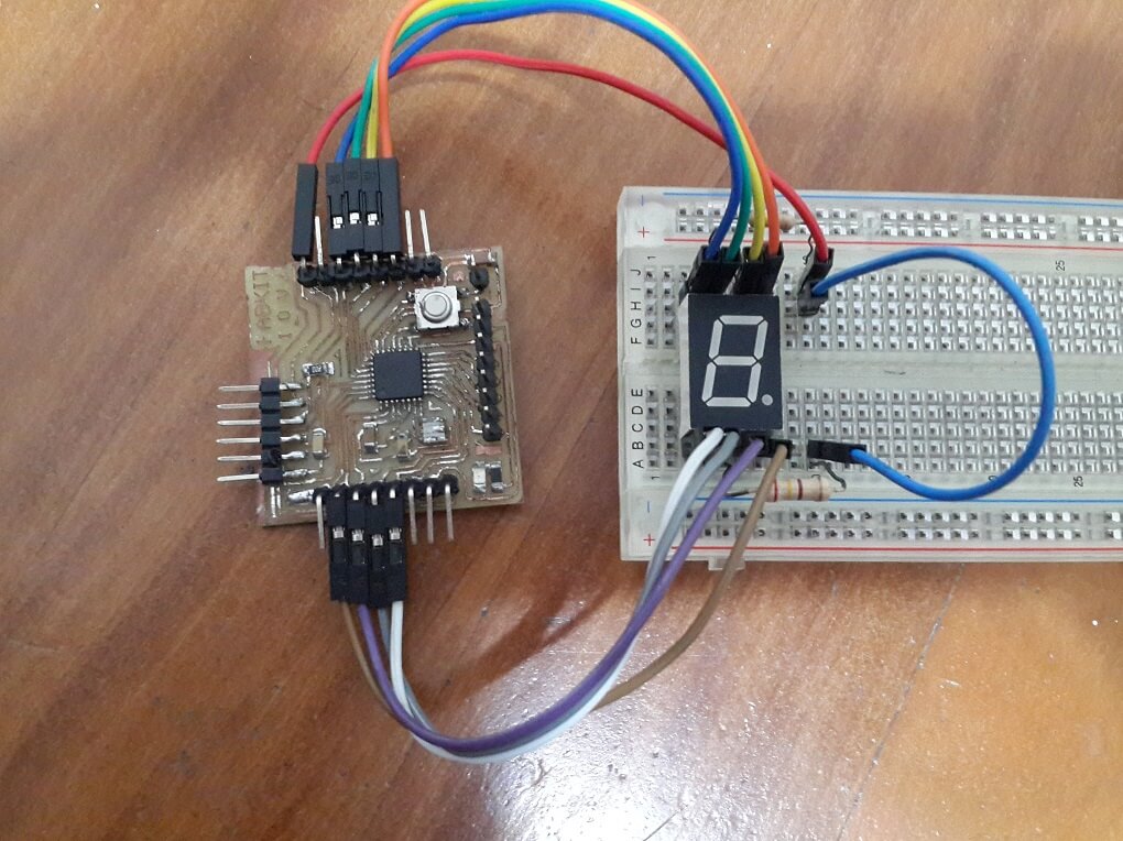
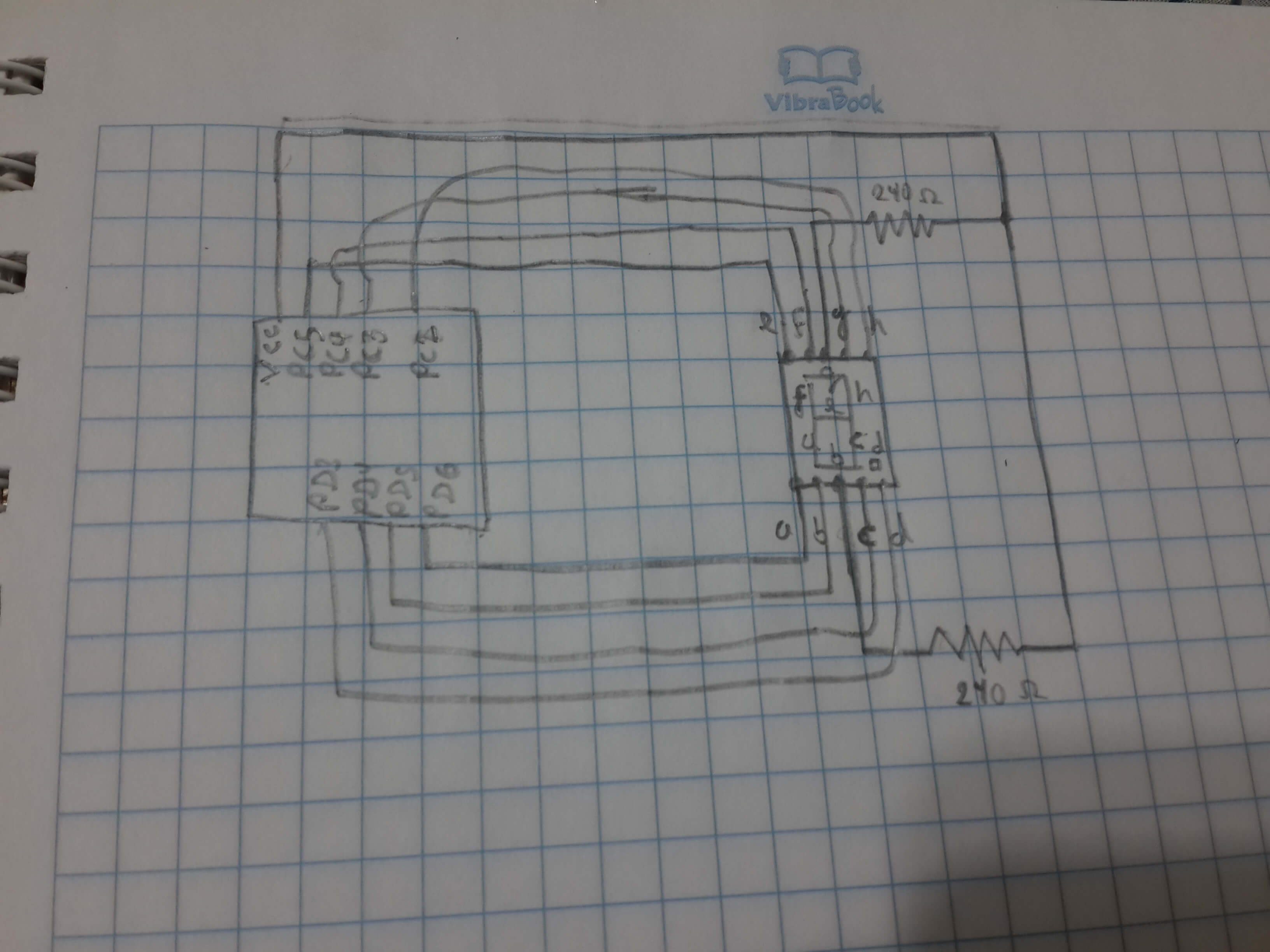
Win AVR Programmers Notepad and C language:In this case, the board was programmed directly whithout the help of a bootloader and the program was written in C language, the purpouse of this code was to show the word FABLAB serially on a 7 segment display mounted on a protoboard. The circuit is the one shown on the image below:
This are the steps I did for programming the board:
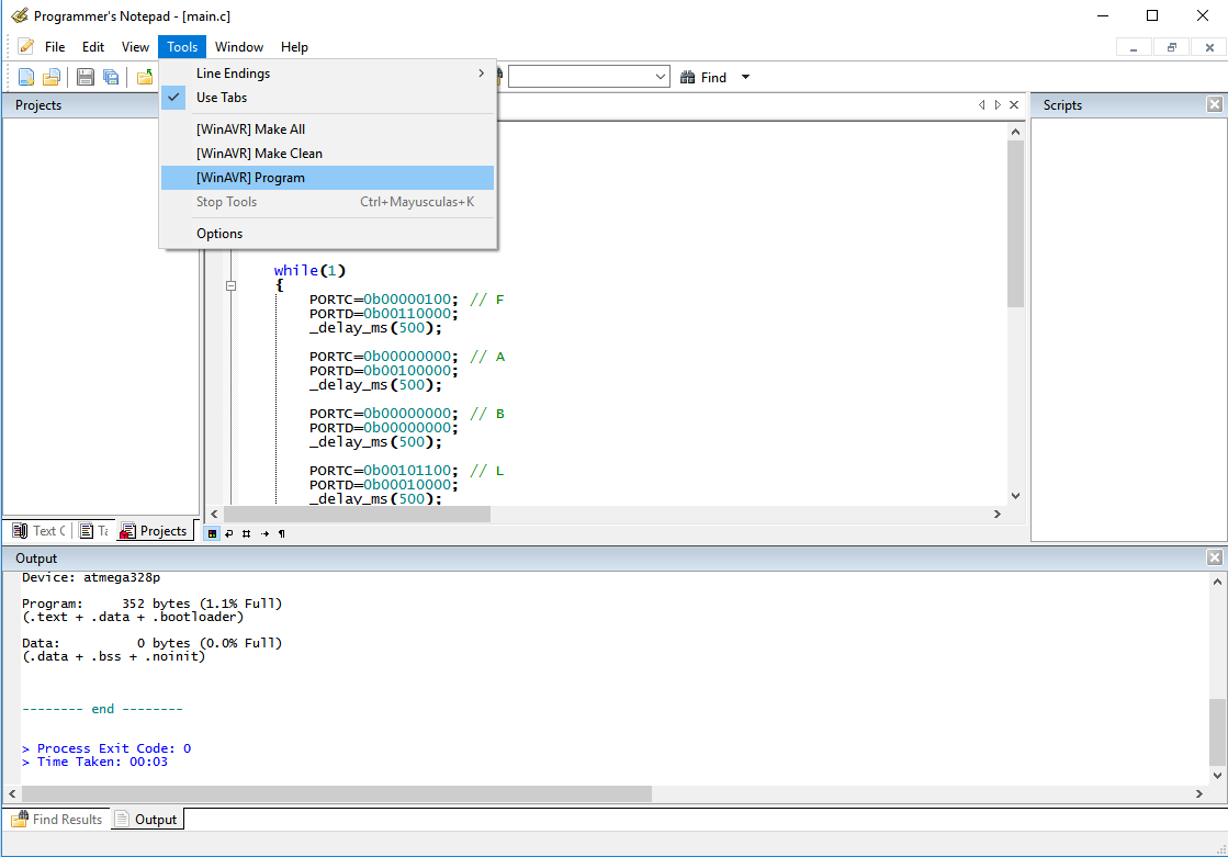
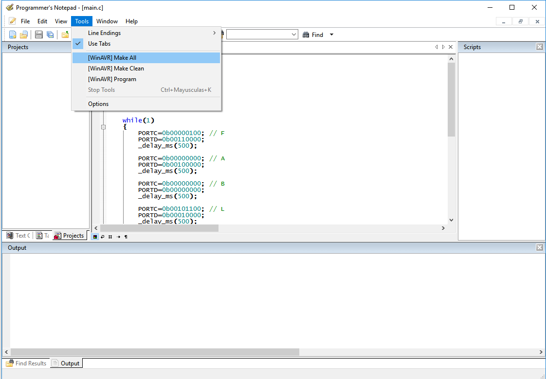
1. First, I oppened the Programmers Notepad software that came with the WinAVR installation.
2. Then, I started to code on the blank window, by importing a library for AVR boards, which permits to modify the microcontroller registers easily, and then continued importing the library for time delays, previously specifiying the clock frequency of the circuit.
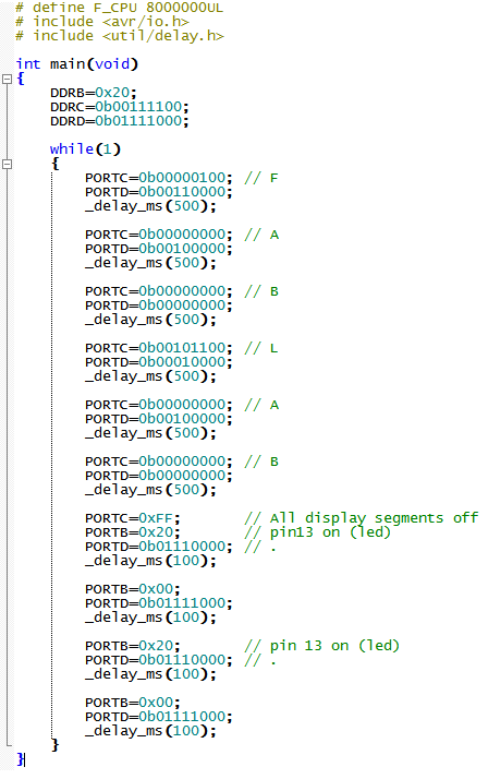
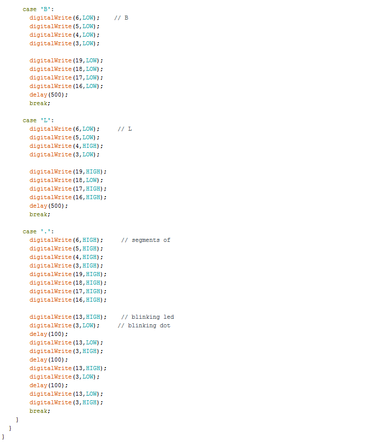
4. By following the display logic (common anode), I determined the value of the output pins for writing each letter of FABLAB and left a delay between each letter.
5. Then, I saved the file with the name main.c (the same name of the main function, if it is saved with other name, the c compiler will not recognize the code).
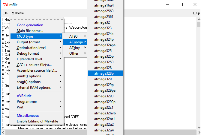
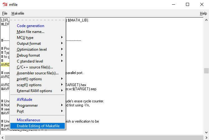
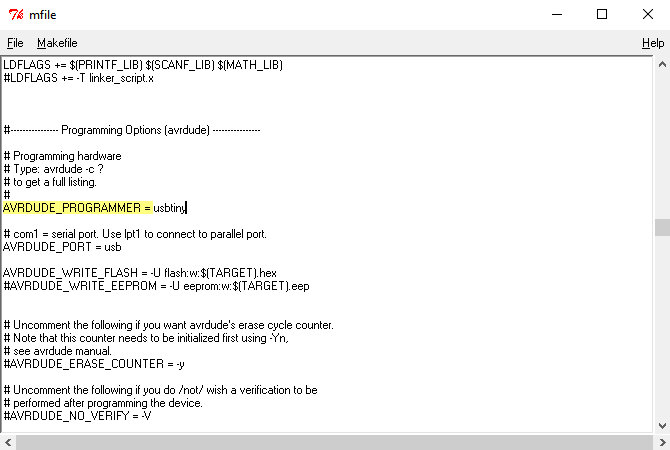
6. After that, I oppened the Mfile software that came with WinAVR installation, for making a makefile that determined the compilation rules of the code.
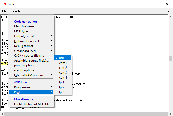
7. On the menu I chose the microcontroller for wich the code was going to be compiled (Atmega 328p).
8. Then, I chose the programming port as usb.
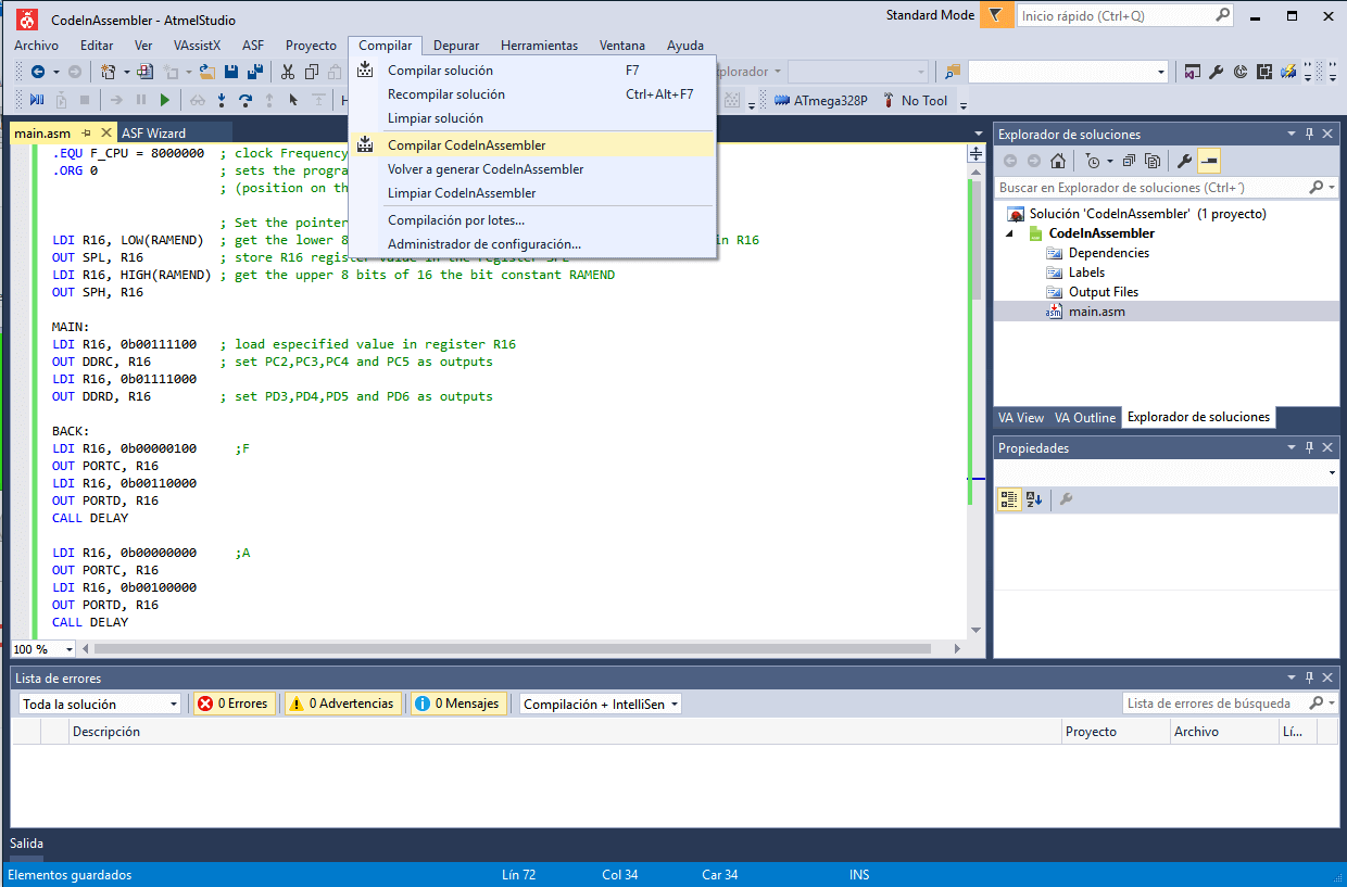
Atmel Studio and Assembly Language(Machine Language)
This time, I wrote a modification of the previous program in assembly language on Atmel Studio. For accomplishing this task I did this steps:
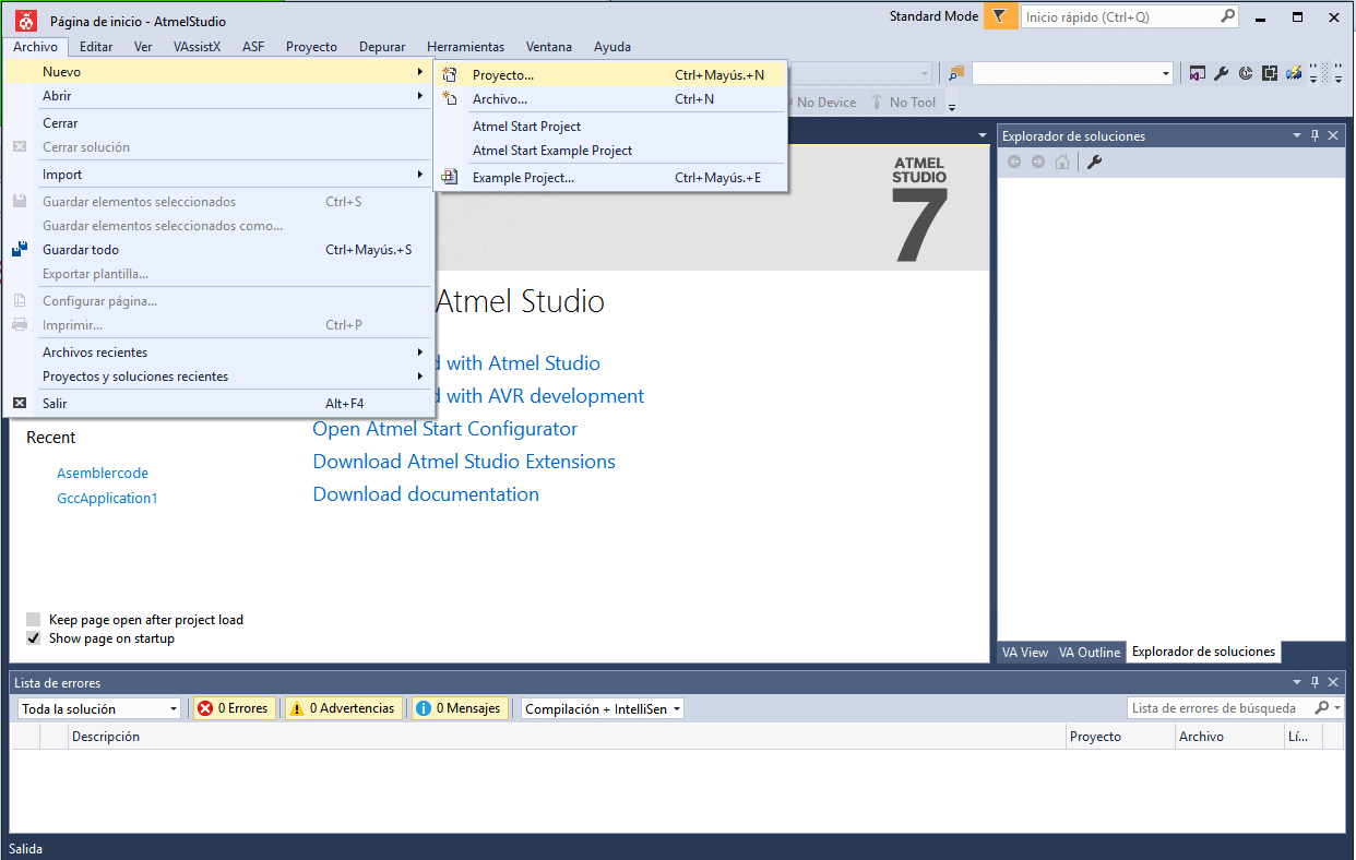
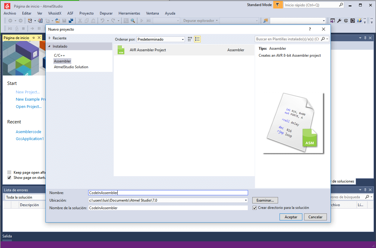
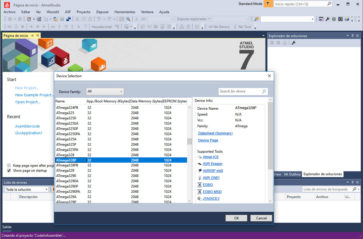
1. I oppened Atmel Studio and created a new project for assembly Language.
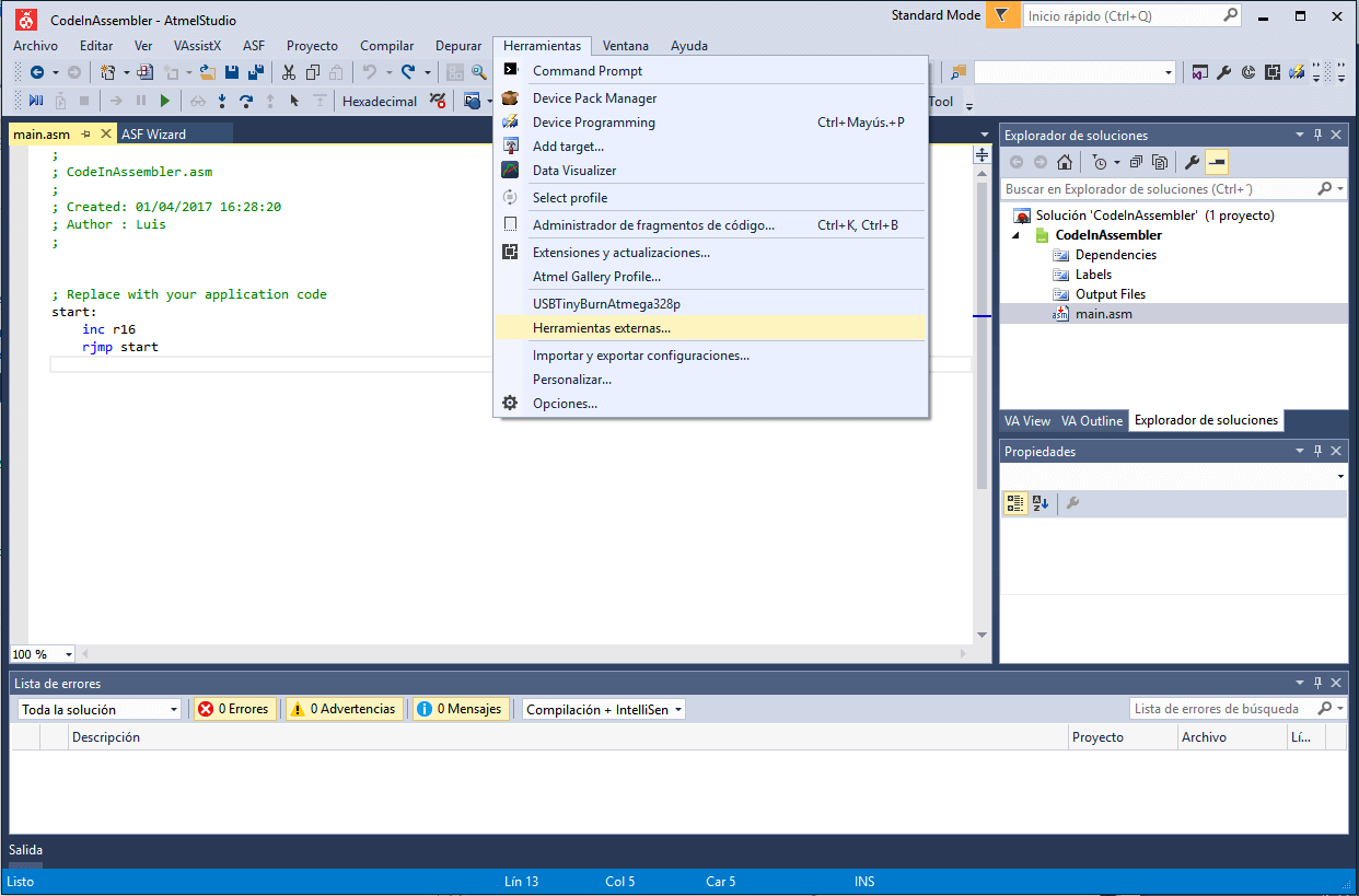
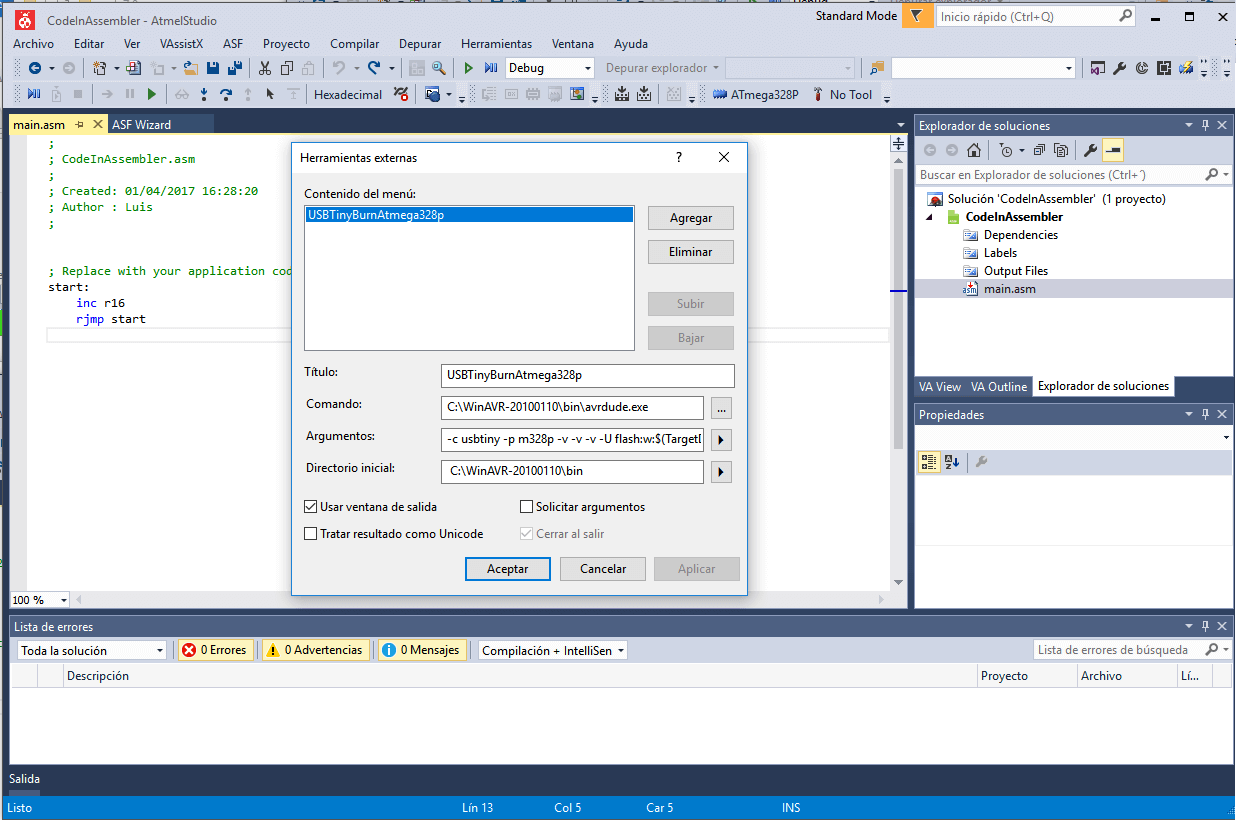
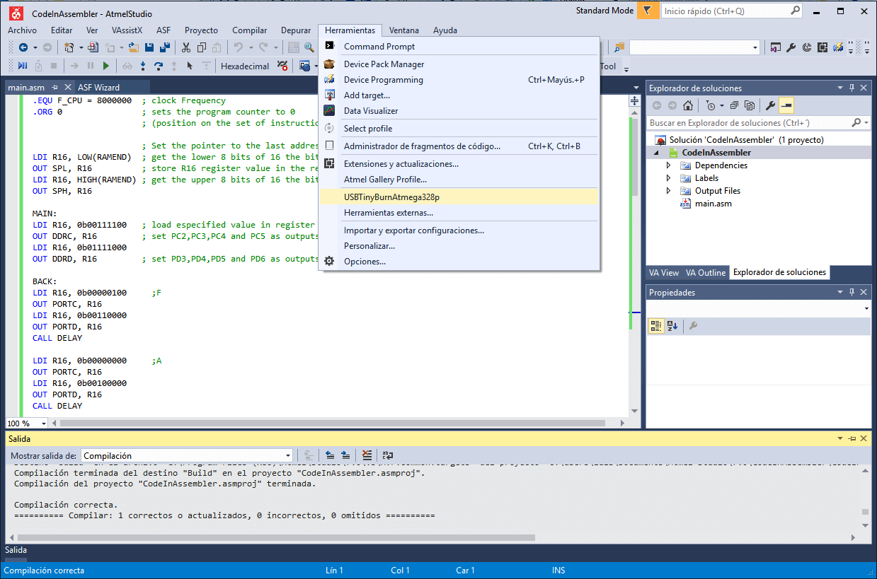
And then adding a new tool with this parameters:
Title: AnyName
Command: C:\WinAVR-20100110\bin\avrdude.exe
Arguments: -c usbtiny -p m328p -v -v -v -U flash:w:$(TargetDir)$(TargetName).hex:i
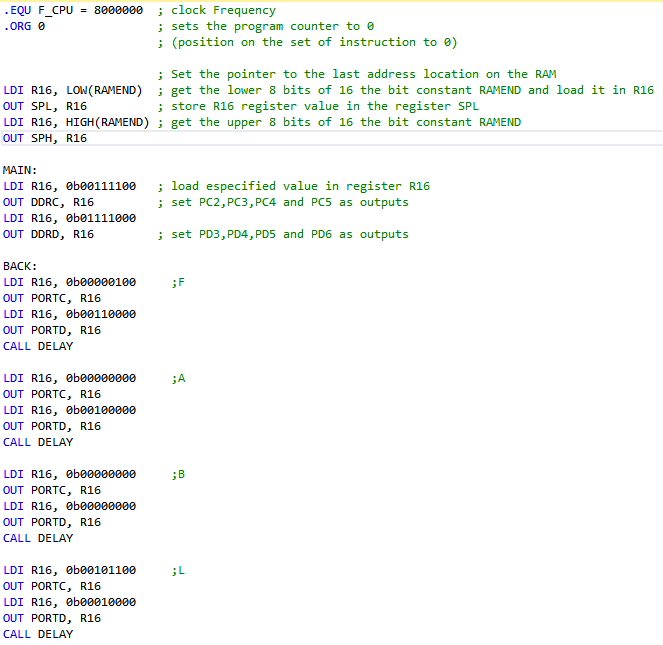
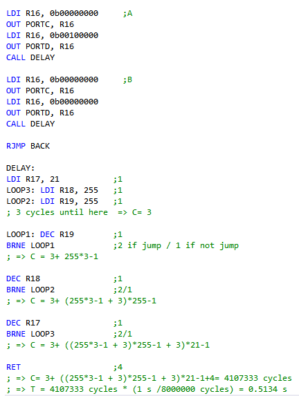
4. I continued defining the output ports and programing the logic for showing the letters FABLAB on the display.
Arduino IDE and C with arduino Libraries:
a) Uploading the Bootloader
Firstly, I conected the board to the pc with the USBtinyISP board I made on the 4th assigment, and powered the board by connecting an USB TTL cable to the board
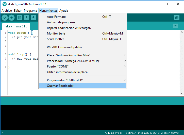
Then, I opnend the arduino IDE, and setted the next parameters as follows:
- Board: Arduino Pro or Pro Mini
- Processor: Atmega328 (3.3v,8Mhz)
- Programmer: USBtinnyISP
Finally, I clicked on Tools->Burn Bootloader and waited until it f inished
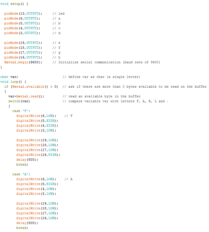
I modified the last code, so that the display were able to show a text sent by serial comunication
b) Uploading and testinng a program:
I uploaded a program to the microcontoller and tested it by doing the next steps:
1. I connected the circuit to the PC with an FTDI cable (USB to TTL cable).
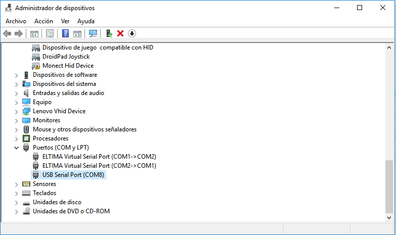
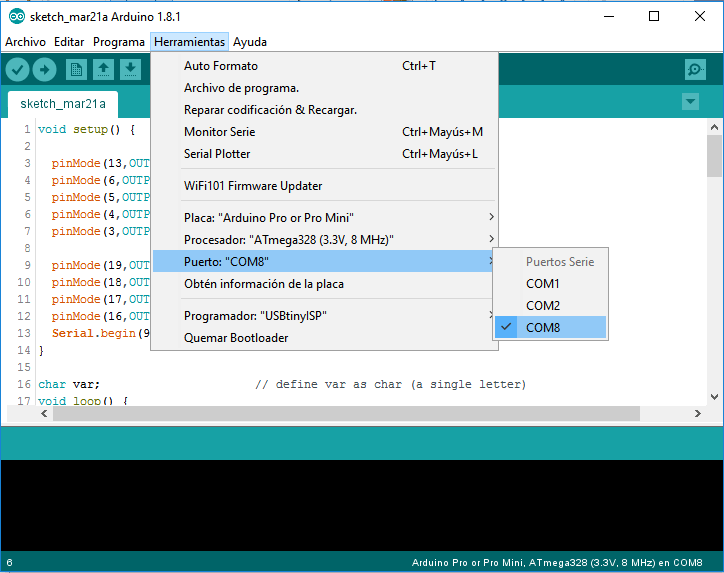
2. I looked for the arduino COM port on the device manager. And selected the COM port on the Arduino IDE.
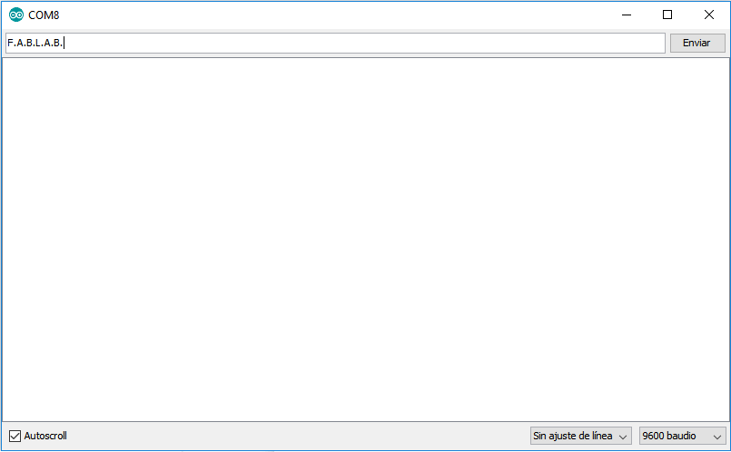
4. After that, I opened the arduino console and setted the baud rate as 9600.
5. Finally, I wrote on the console F.A.L.A.B. and clicked on send, this sends the string F.A.B.L.A.B. from the pc to the arduino by serial comunication.
Just to mention, in spite that I know how to progam this microcontroller by its ISP port, which includes some of the lines of the SPI communication, I do not really know what is sent by this port when the microcontroller is programmed and if it uses SPI or a similar protocol of comunication. So, definetly, I would like to learn more about ISP programming.