Week 15
Networking and Communication
Final Project
ASSIGNMENT
Design and build a wired &/or wireless network connecting at least two processors
For Networking I Started Exploring the Class page and read about all protocols available.
http://academy.cba.mit.edu/classes/networking_communications/index.html
Testing How Serial Communication Will Work

I chose to Do the Asynchronous Serial Communication.
To Test The Same if it works I used the servo board form output device assignment

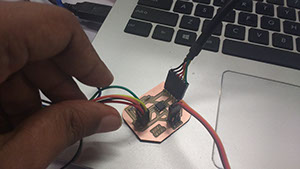
I used the FTDI Cable as above and Loaded Below Code.
#include <SoftwareSerial.h>
// ***
// *** Define the RX and TX pins.
#define TX 3 // PB3, Pin 2 on attiny45 leg
#define RX 4 // PB4, Pin 3 on attiny45 leg
SoftwareSerial mySerial(RX, TX);
char chr;
void setup() {
// initialize serial communications at 9600 bps:
mySerial.begin(9600);
pinMode(3, OUTPUT);
}
void loop()
{
char chr = mySerial.read();
mySerial.read();
if (chr == 'a') {
for (int i = 0; i < 50; ++i) {
digitalWrite(3, HIGH);
delayMicroseconds(2000);
digitalWrite(3, LOW);
delayMicroseconds(18000);
}
}
else if (chr == '0')
{
for (int i = 0; i < 50; ++i) {
digitalWrite(3, HIGH);
delayMicroseconds(1000);
digitalWrite(3, LOW);
delayMicroseconds(19000);
}
}
else
{
}
}
GET FILE
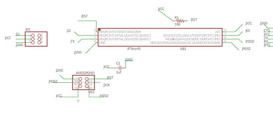
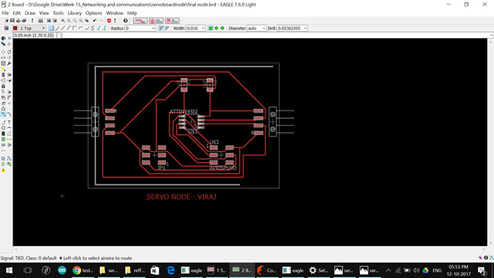
As we Can see in Schematic above, our servo is connected to PB3 which is reffed as pin 3 from Arduino.
Attached is pin map of ATtinny 45
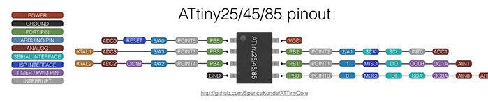
Rx and TX pin are connected to pin 3 and 4 (arduino Reference) of the ATtiny 45
Though we only need the Rx pin so that the board can receive the data
- The way the code is working is that when I Press 0 over the serial Monitor it turns to 0 degree.
- And when I press a it turns to 45 Degree
As we are reading only one character from the input only the first character is read.
This way each character is read as a septate input.
Below is the Video of the Same.
Designing New Board.
Now I Went ahead and designed a new board.
The changes to the original board are as follows
Now I Went ahead and designed a new board.
The changes to the original board are as follows
- As we can see in the above Schematic image, I forgot to connect the SCK pin to AVRIPS pin header last time i have to make provisions for that
- As seen on the Yellow Maker in this image
We had to connect it form the FTDI pin header - Also for ease of routing TX and RX pin are kept closer.
- So now We need a PWM pin for Servo and thus based on some reading Online i found out its ok to use MOSI pin for the same
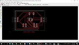
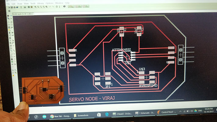
Below is the Screen Shot of new Schematic
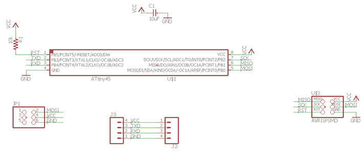
Arranged the pins as above
Have taken a 6 pin header for Servo because it will give better grip of header over board.
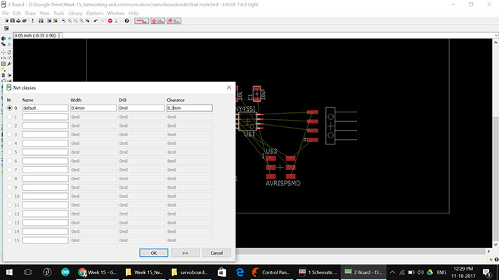
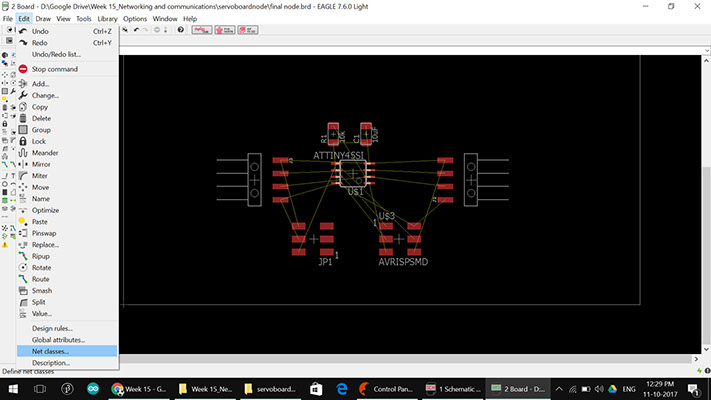
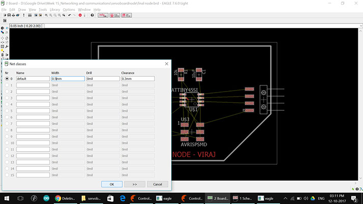
Net Classes Settings
Trace Width : 0.4mm
Clearance : 0.3mm
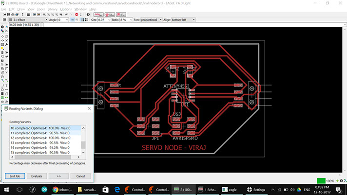
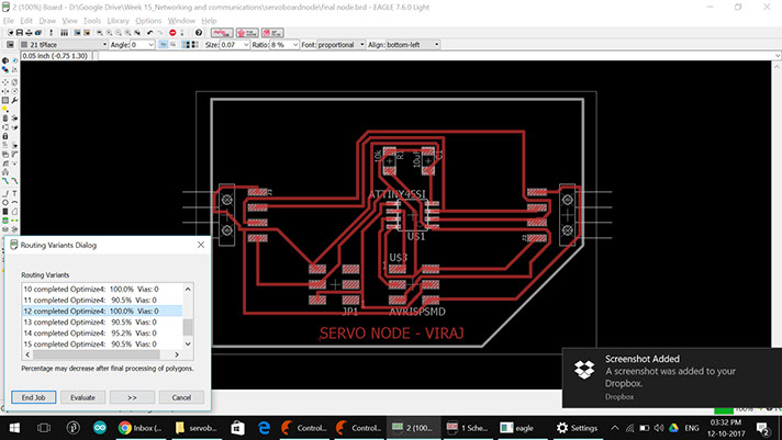
Few Auto Routing Options
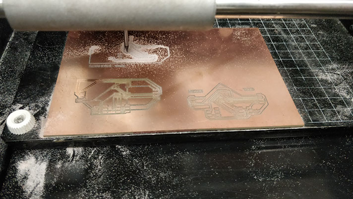
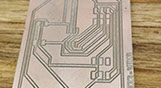
Version 1
Thats First Day of Modela in New location for FABLAB CEPT
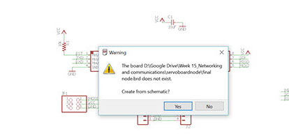
Error !!
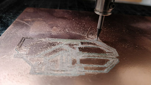
As we Can See The Trace Came out Badly and it pealed off.
Something is Wrong with Modela
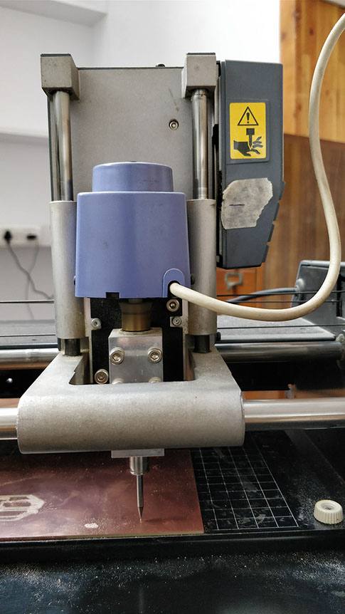
Solution !!
As we Se in the Image Below Following The Milling Of the Board will be same as the head was too low.
We need to keep the modela head above this line.
This has been discovered by My Friend Gautam Prakash (Student Fabacademy)
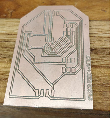
Version 2
Until The above error was found, I also change the PCB design a bit.
And Re Routed the Path.
Error !!
On My second attempt I realized that the traces are too close which has caused the above error.
Solution !!
Solution of this will be to increase the path width. which is as shown below
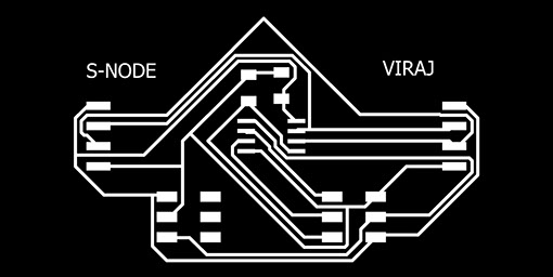
Version 3
Now we have to change the path width
I used the RIPUP Command to remove all path and keep the connections
changed the width and used autorouter to rout new path.
Net Classes Settings
Trace Width : 0.5mm
Clearance : 0.3mm
What I changed is the Trace Width to 0.5mm form 0.4mm earlier.
But this gave me hard time doing Auto-routing.
Was not able to get the 100% complete path.
So I Seprated the components little more away form each other and tried again.
And it Worked. !!
Changed Trace width to .5 mm
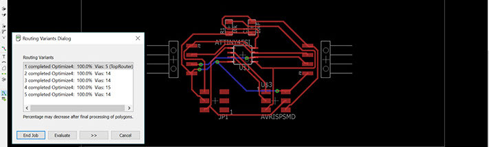
Routing Option 1
Traces are too close again
The process
3 - 4
<
>
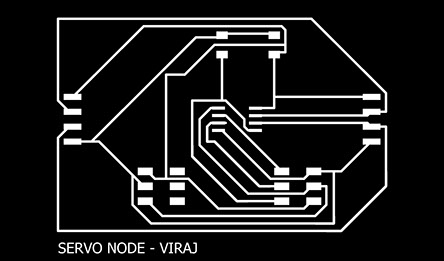

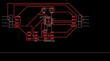
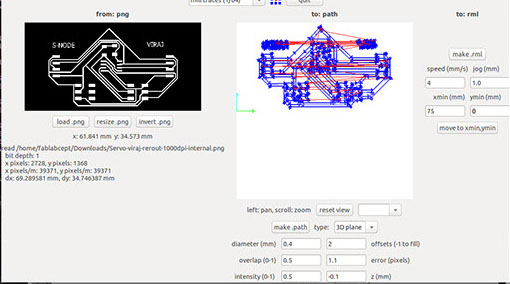
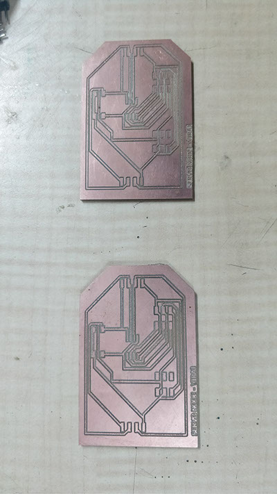
This time the path was well isolated and the images are exported at 1000 DPI for eagle cad. CAD files for the same are attached at the bottom of the Page.
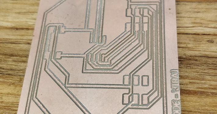

Changed Trace width to .5 mm
The Trace Came out Well this time.
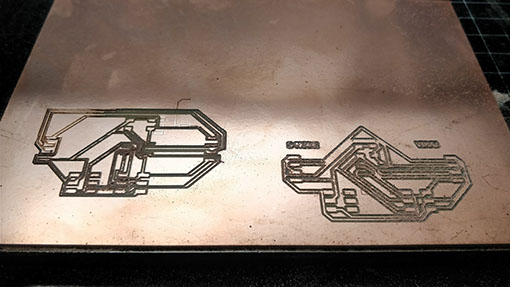
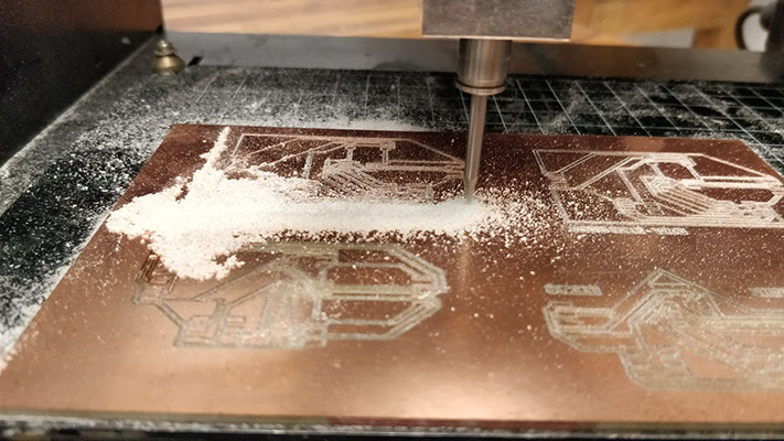
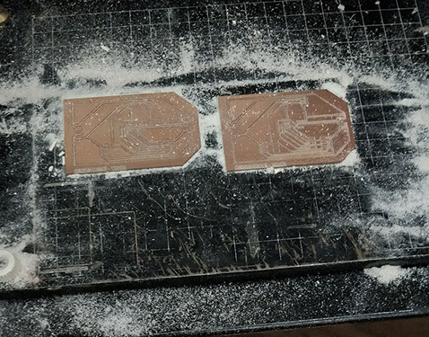
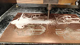
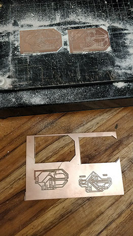
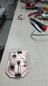
Cutting out both board at same time
Finally !! Both Board Came out perfect
Traces are too close again5
5 - 5
<
>
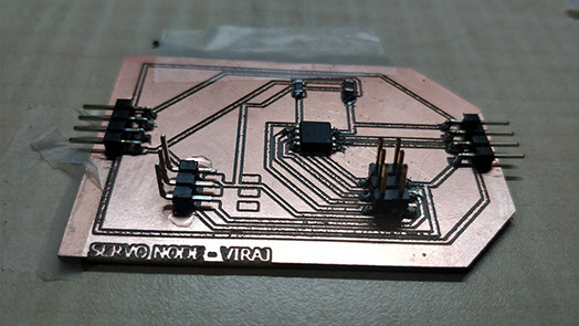
- I soldered both the boards at one go.
- As seen above for servo i used the L shape pin header and stick it with some glue to hold it in place then went ahead and connected the trace with extra solder drop.
- This gave a excellent hold over the board.
PROGRAMMING for Testing
Programmed both the board with Servo Sweep Code to check if both of them work
GET FILE
Servo Sweep 45 Code Attached
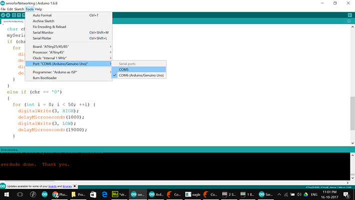
I programmed both board via AVRISP selection above options.
the wiring is shown below.
As we can See both the Board are Working Perfectly now we move forward to add serial commutation to it and make do the same when we give some command.
PROGRAMMING With ADDRESSING
So What we have is
- 2 New Servo Board with RX and TX pin outs
- 1 board from Week 10 output Board
Now Each Node Is programmed with below code and only the address that is
a or b or c has been changed in each one.
#include <SoftwareSerial.h>
// Viraj Gandhi
#define TX 3 // PB3, Pin 2 on attiny45 leg
#define RX 4 // PB4, Pin 3 on attiny45 leg
// These constants won't change. They're used to give names
// ***
// *** Define the software based serial port. Using the
// *** name Serial so that code can be used on other
// *** platforms that support hardware based serial. On
// *** chips that support the hardware serial, just
// *** comment this line.
// ***
SoftwareSerial Serial(RX, TX);
char id = 'a'; // the address of this Node
const int servopin = 0; // Sevo Pin
char chr;
void setup() {
// initialize serial communications at 9600 bps:
Serial.begin(9600);
pinMode(servopin, OUTPUT);
// delay(5000);
Serial.println("Node ");
Serial.print(id);
Serial.println("Online");
}
void loop()
{
chr = Serial.read();
if (chr == id) { // if true next commands are or this Node.
chr = Serial.read(); // we read recond character following it
if (chr == '1') {
for (int i = 0; i < 30; ++i) {
digitalWrite(servopin , HIGH);
delayMicroseconds(2000);
digitalWrite(servopin , LOW);
delayMicroseconds(18000);
}
// Serial.print("Node ");
// Serial.print(id);
// Serial.println(": ON");
// digitalWrite(servopin, HIGH); // FOR DEBUGGING
}
else if (chr == '0')
{
for (int i = 0; i < 30; ++i) {
digitalWrite(servopin , HIGH);
delayMicroseconds(1000);
digitalWrite(servopin , LOW);
delayMicroseconds(19000);
}
// Serial.print("Node ");
// Serial.print(id);
// Serial.println(": OFF");
// digitalWrite(servopin, LOW); // FOR DEBUGGING
}
else
{
// digitalWrite(servopin, LOW);
}
}
}
GET FILE
the Code attached is Version 4 of my personal update but it is the final code for the NODE we have above.
The First IF block checks if the Message is for The particular node
- If yes the code watches the command and executes it
- either 1 turn on
- or 0 turn servo to off position
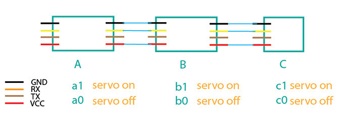
ATtiny45
node
ATtiny45
node
ATtiny45
node
For Example if the command is b1 the second servo named B will turn on.
list of all possible commands
- a1
- a0
- b1
- b0
- c1
- c0
Changed Trace width to .5 mm
Routing Option 1
Traces are too close again
The process
3 - 4
<
>
Address Command
a 1
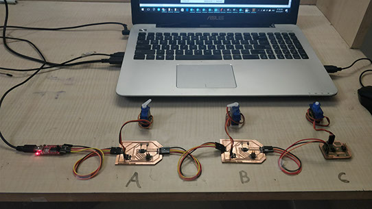
What we can see is the network of Attiny45 NODES is connected to laptop via FTDI cable.
When I give commands the nodes pickup the command for itself and does the action mentioned
ADDING A MASTER BOARD TO NETWORK
I used the 328p Board which I have made for Final Project as a master board.
I used FTDI Module as below to program it as it was already Boot-loaded with Arduino Firmware
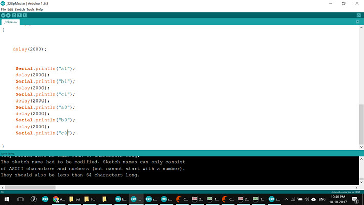
The code to program the Master board is a Below.
//#include <SoftwareSerial.h>
//#define RX 4 //
//#define TX 2 //
// These constants won't change. They're used to give names
// ***
// *** Define the software based serial port. Using the
// *** name Serial so that code can be used on other
// *** platforms that support hardware based serial. On
// *** chips that support the hardware serial, just
// *** comment this line.
// ***
//SoftwareSerial mySerial(RX, TX);
void setup() {
// initialize serial communications at 9600 bps:
Serial.begin(9600);
}
void loop()
{
Serial.println("a1");
delay(2000);
Serial.println("b1");
delay(2000);
Serial.println("c1");
delay(2000);
Serial.println("a0");
delay(2000);
Serial.println("b0");
delay(2000);
Serial.println("c0");
delay(2000);
}
GET FILE
the Code attached is designed for my 328p Master,
broad files shared Below
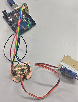
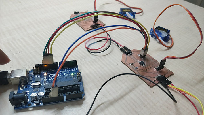
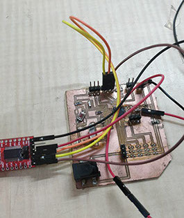
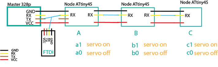
Once Programmed I connected The Master 328p board with The 3 Node Network As Belows.
- We are Reading The Serial Communication Happening Between Them as Belows.
- The Tx Pin of 328p will connect to Rx pin of FTDI and All Nodes.
- The FTDI is probling the Serial communication between Attiny45 Nodes and 328p Master.
- The Master Give a command every 2 Second to the network and Respective Node Executes.
- As seen form code above all communication is happening at 9600 Baud Rate
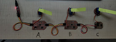
Later I connected Removed the FTDI Cable and powers the network form 5v Battery.
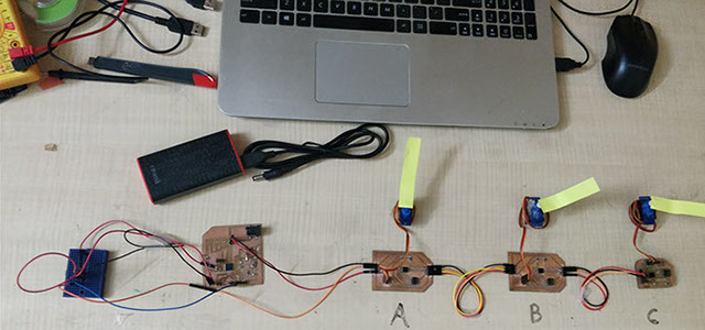
The Whole network can be seen working independently as below.
As we can see the Whole Network is Working on its own based on the commands from the Master Board. Finally Is all Working Together !!
Following Files are Attached
GET FILES
- Schematic Eagle Servo Node attiny45
- Board Eagle Servo Node attiny45
- Schematic 328p Master (made for Final Project)
- Board file 328p Master
- Code ATtiny 45 Node
- Code 328p Master
LEARNINGS OF THE ASSIGNMENT
- Better Understanding of Serial Communication
- Until now I believe serial communication can only take place between two devices, A Myth was busted for me :)
- Perfect The Milling Process further with Modela.
- I have Also Read about I2C Communication and explored possibility of its use in final project.
- Lastly This was the Assignment I enjoyed the most as I got better results then expected. Thanks to Mohit Ahuja, Gautam Prakash and Arpi Maheshwari for Quick Support During This Assignment.