Week 3: Computer Controlled Cutting
Tasks for the week:
- Design a product developed along the lines of parametric design using 'press-fit' construction technique
- Learn to use vinyl cutter and use it for a purpose
Task:01
Design a product developed along the lines of parametric design using 'press-fit' construction technique
This week the assignment was to create a parametric form using 'Press-Fit' joinery. For this, it was required to use a parametric software so I chose Grasshopper for this.
Parametric: Unlike a 3D static model created through primitive geometries, a 'parametric' model can be considered as a dynamic system of relations among different objects.
.jpg?crc=3761646784)
.jpg?crc=60783455)
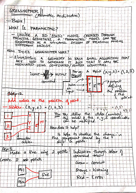
The above images show my explorations of understanding how to construct a line in grasshopper.
.jpg?crc=496641354)
.jpg?crc=3892487068)
.jpg?crc=4234189634)
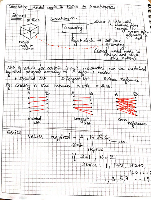
The above images show my explorations of understanding how to construct a line in grasshopper.
Next, I modelled an object in Rhinoceros and then tried converting it to grasshopper geometry by creating a geometry domain in grasshopper.
.jpg?crc=4191278503)
Next to start scripting the waffle, my first step was to create a bounding box around my geometry to generate the x planes and y planes that shall be used for the waffle.
.jpg?crc=3901252394)
After constructing the x and y planes required for slicing the object into a grid the next step was to add more slicing planes to the object.
.jpg?crc=406064233)
After constructing the x and y planes required for slicing the object into a grid the next step was to add more slicing planes to the object.
.jpg?crc=3920689188)
Now since I got the slicing planes in x and y direction to get the form of my geometry, I needed to get the intersection planes of the x-y planes with my geometry. I used Brep intersect command for this.
.jpg?crc=124525754)
As a result of my previous step, I got the intersections as shown above. Now these curves needed to be converted to surfaces so I used Boundary surface to convert these lines to surfaces.
.jpg?crc=463612652)
Now, by dividing the lines of intersections in two parts, I created cylinders in upward and downward direction that would act as notches for press-fit.
.jpg?crc=4055771545)
Final step is to trim the surfaces with the cylinders to get the notches in the slicing planes.
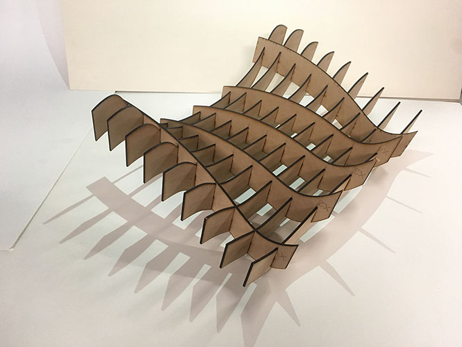
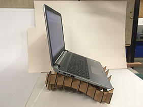
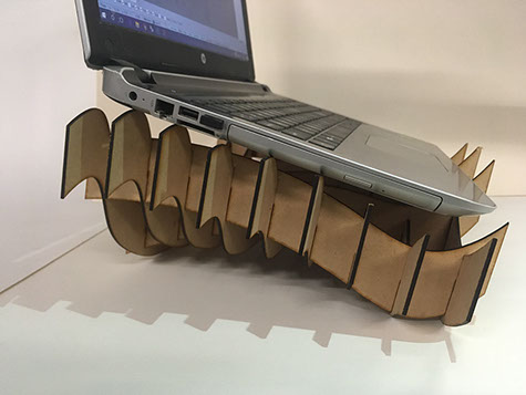
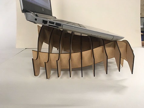
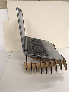
So, this is how I prepared the script for the waffle structure. Now I had to use this script for a parametric surface that would work as a laptop stand for my laptop.
Also, to create the above script, I took help of the below seen tutorial. Super easy to understand!
-crop-u3843.jpg?crc=431243863)
Step:02
Designing a 'Parametric' Laptop Stand using 2.5 mm thick MDF board
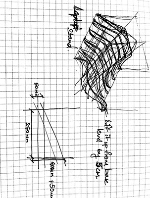
My idea was to create a surface constructed with press-fit joinery with a waffle form that can be used as a laptop stand. So first I took the dimensions of the base of my laptop. It can be seen in the sketch on the right. Then I sketched a probable form.
Since I needed a 20 degree angle, I didnt want it to look like a slope. So I started experimenting with the form of the surface using curves and modelled a few options in Rhinoceros as seen in the left image.
-crop-u3525.jpg?crc=298743584)
-crop-u3836.jpg?crc=127183153)
-crop-u3518.jpg?crc=276523767)
.jpg?crc=465783703)
Now, as my next step, I created my curves to parametric curves using grasshopper by dividing them into several points and each of them can be moved in Z direction to adjust the height of the curve as required.
.jpg?crc=3878752843)
Next after generating my surface from curves, I extruded it to get the required thickness of 5 cm and then applied the script that I made for waffle structure over it to get the x and y planes for the geometry.
.jpg?crc=383712508)
.jpg?crc=447168016)
The image shows the surface that can be modulated in Grasshopper.
The image shoes the application of the script that I made on the surface. The surface got divided into planes that in X and Y planes that fit together to form the surface.
.jpg?crc=345068895)
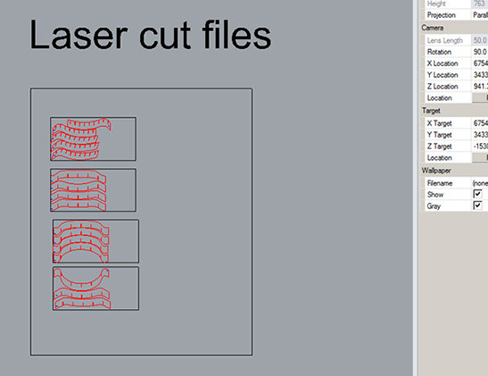
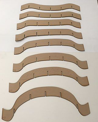
Next, I extracted the line drawings by using the command 'make 2d' for each plane and nested them as per sheet size 600x 300 mm.
I followed this tutorial on youtube to make the script.
Step:02
Laser Cutting and Assembling
After making the files, my next step was to fabricate it. I chose to fabricate it by laser cutting 2.5 mm thick MDF board.
I divide my file in two layers:
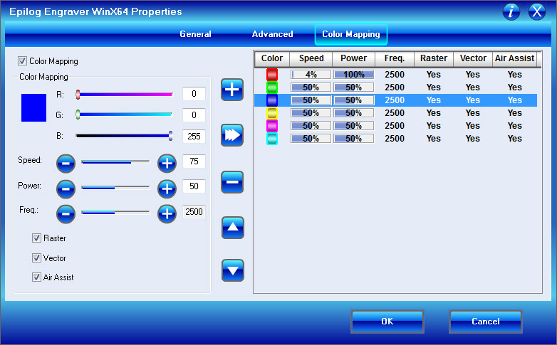
Blue: Engraving
Red: Full cut
Parameters:
Blue:-
Speed: 75, Power:50, Frequency: 2500
Red:-
Speed: 4, Power:100, Frequency: 2500
Below image shows the parameters that I chose.
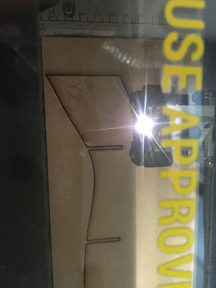
The above image shows the process of laser cutting.
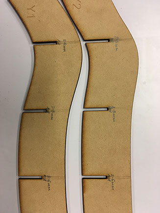
I tried various cut notch sizes like 2.4 mm, 2.5 mm and 2.6 mm to check which one of these gives the best friction between two components. 2.4 worked out to be the perfect one.
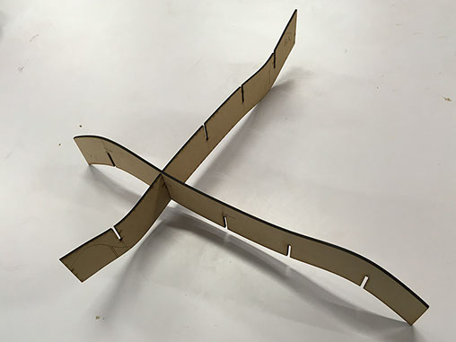
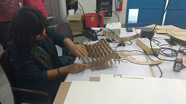
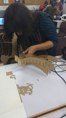
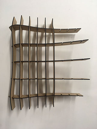
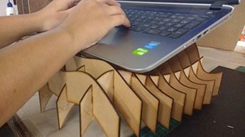
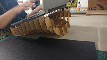
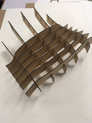
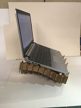
Below is a collage of images that describe the process of assembling the laser cut components:
.jpg?crc=3928479593)

Files for this assignment can be accessed here.
Task:02
Learn to use vinyl cutter and use it for a purpose
This week we decided to screen print our own T-Shirts at the Lab. So we decided to cut the desired pattern in the vinyl cutter, then use it as a stencil on the screen printing apparatus to print the pattern on the t-shirt.
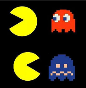
I decided to make a 'Pacman' themed print. I had seen a similar print before. So tried replicating it.
Step :01
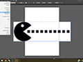
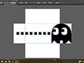
I started by choosing a suitable image for my graphic. Below are the images that I downloaded from the internet.

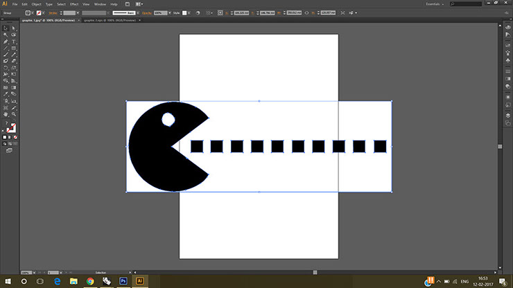
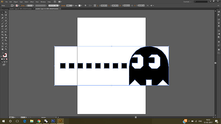
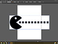
So, first I placed the black and white graphic on the art board, and then selected it. Next clicked on 'Image Trace' button that appears right below the title bar. The above image shows the result after clicking image trace
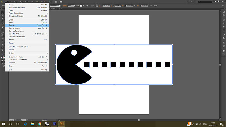
That gave me boundaries of the graphic. So i saved it. For that I went to File menu and then clicked 'Save As'. I saved it as '.eps' file.
I did the same process for my other graphic. I decided to print two graphics on two t-shirts.
3 - 3
<
>
Step:02
I opened the graphic in Adobe Illustrator cs6. The process is as below:
Adobe Illustrator:
"Adobe Illustrator is a vector graphics editor developed and marketed by Adobe Systems. The latest version, Illustrator CC 2017, is the twenty-first generation in the product line."-Link
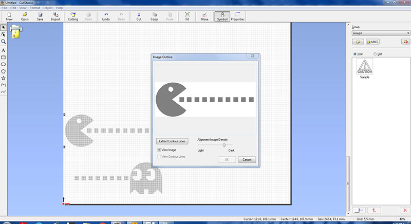
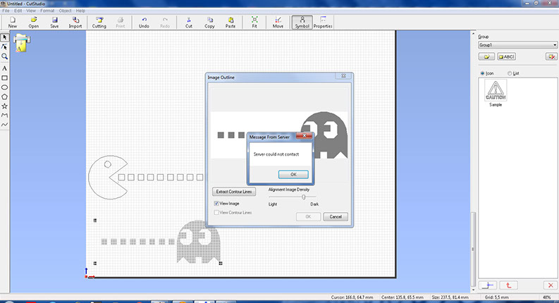
First I imported files from the import icon in the task bar and selected the imported graphic, right clicked on it and extracted the contour lines.
I followed the same process for the second graphic and extracted its contour lines for cutting.
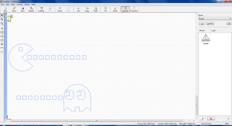
As seen above, I got the edges of my graphic from the previous process so now next step was to cut it.
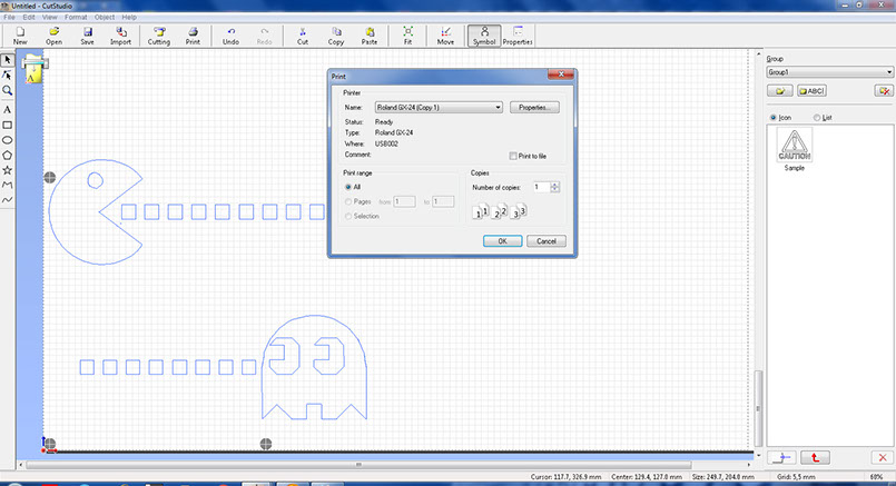
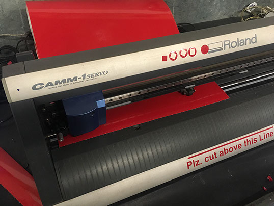
For, cutting I clicked on the print icon and selected the Roland GX 24.Next I followed the steps mentioned beow to prepare the machine for cutting.
<
>
Preparing the cutting file in Cut Studio:
Points to be kept in mind:
- The vinyl roll needs to be placed within the white markers.
- Set Origin: For this, origin button has to be long pressed to set the origin.
- Cutting Force: I used 230 as the value for force. Press force button to go to the menu. Next press the right side button to select force. Up-down buttons are used to set force value. At last press Enter to fix the force value.
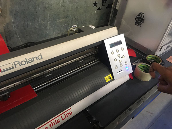
The images are from the process of configuring the values on the machine.
Process of Screen Printing:
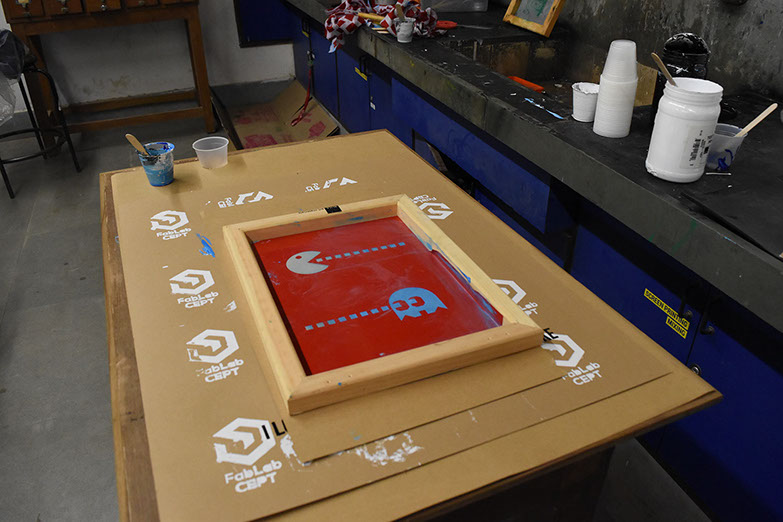
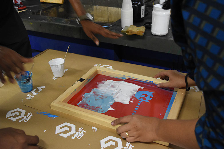
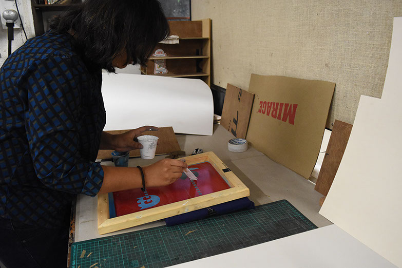
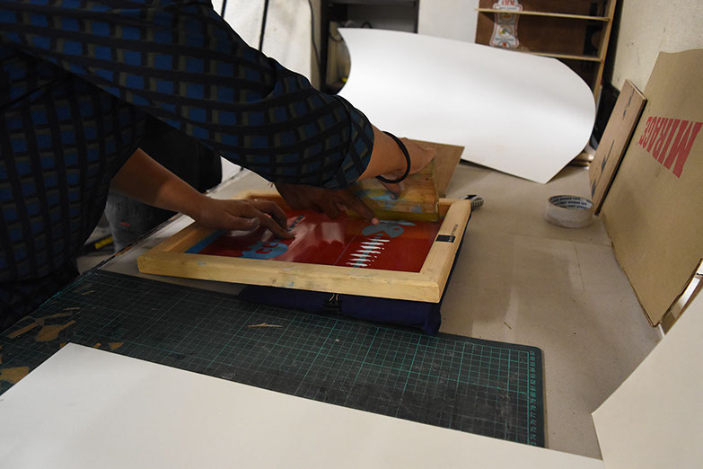
First, I stuck the vinyl sheet that i had cut onto my screen . As seen in the picture, my graphic got cut nicely and so i decided to do a test print first.
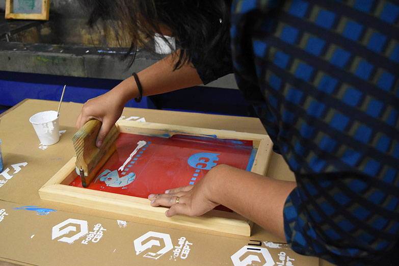
So, I dripped some colour around the graphic, and dragged the rubber squeezee over it to spread colour on the graphic. Since the rest of the part (Other than graphic) was sealed with vinyl sheet, the colour only spreaded through the graphic edges.
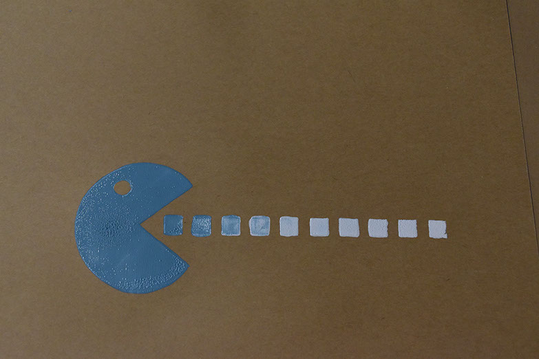
I wanted to try gradation using two colours. So thast what I tried.
It came out well. The gradation worked. It looked perfect. So I went ahead to print it on the T-shirt.
I wrapped the tshirt on a board to avoid creases in the t shirt fabric, then laid my screen over it and went ahead with the process of printing.
I followed the same process as before.
Results were good again. I used less colour, because I wanted a faded look of the graphic.
>
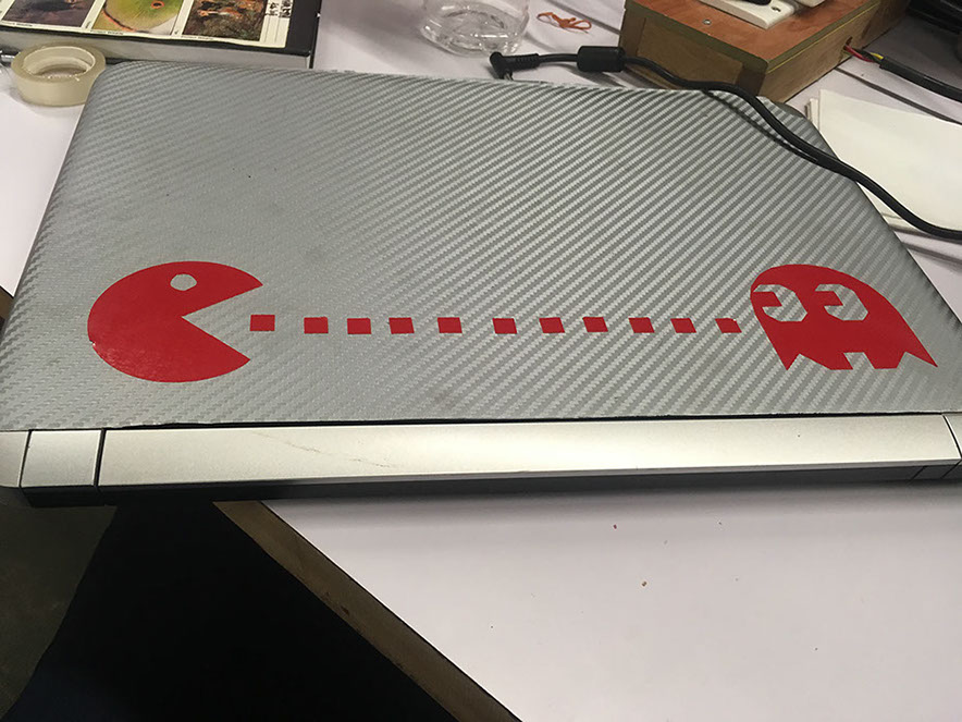
I used the negative of the vinyl print as sticker for my laptop.
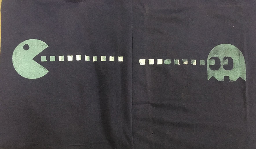
The image shows the final graphic printed on the T-shirts
Files for vinyl cutting can be accessed here.
Step:01
Learning Grasshopper
" What is Grasshopper?
- Grasshopper is a visual programming language and environment developed by David Rutten at Robert McNeel & Associates,that runs within the Rhinoceros 3D computer-aided design (CAD) application. Programs are created by dragging components onto a canvas. The outputs to these components are then connected to the inputs of subsequent components."-Source: Wikipedia
To begin my exercise for this week, I started with learning grasshopper as a tool to create parametric forms. For this, I started referring to the book "Parametric architecture" by Arturo Tedeschi. As seen in the images below, I started making notes about what I understood about logics in grasshopper.

EX-TERRA-DUR by Chandni Chhabra is licensed under a Creative Commons Attribution-ShareAlike 4.0 International License.