Computer-Controlled Machining Make something big
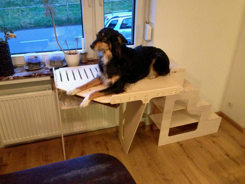
Starting this weeks project I planed to build a replacement for a platform I build for my dog a year ago. The platform enables my dog to look out of the window. She lays a lot on it. When I build this it was a test to see if she is using it. Because it don't look very nice I wanted to rebuild it a bit nicer and with stairs, so that the dog can climb the platform easier in the future.
Measuring the old part get the shape
Fist I startet to measure what is already there. To become an idea about the size of the model that I want to build. I wrote down the most important sizes of the current platform.
| 80cm x 60cm platform | 2cm window board thickness | 2,6cm window board to wall depth | 102cm wall space right | 4cm window to wall | 86cm window board height | 90.5 platform height |
Design the stand it was all about fillets
Software I used my toolkit
Fusion 360
Fusion 360 is from Autodesk. It's similar with Inventor but it's cloud based. The best advantage that it has in comparison with Inventor is, that it can be installed on my Mac. So I can use it at my Windows workstation at home and on the go on my Macbook.
Rhino 5
Rhino is a professional 3D CAD tool. It is also capable to work with 2D vector graphics.
For the development of the new stand I choose Fusion 360 again. Because I become more and more familiar with it, I will focus on it in future projects to become an expert on it.
I started my Fusion 360 project with some sketches and used the sizes I wrote down before to model everything specific for my needs. I split the model into several components that every part can easy changed. Components are also useful specifically when developing something that later consist out of flat material that hold together with a pressfit construction. Because when you have all the parts separate in components, you are able to detect collisions between them. There is a function in Fusion where you can select two components and it shows where the two parts are using the same room space. Later you can use components on each other to remove such space. The result is something where you can be sure that no part has some material on a joint section where it can collide with another part.
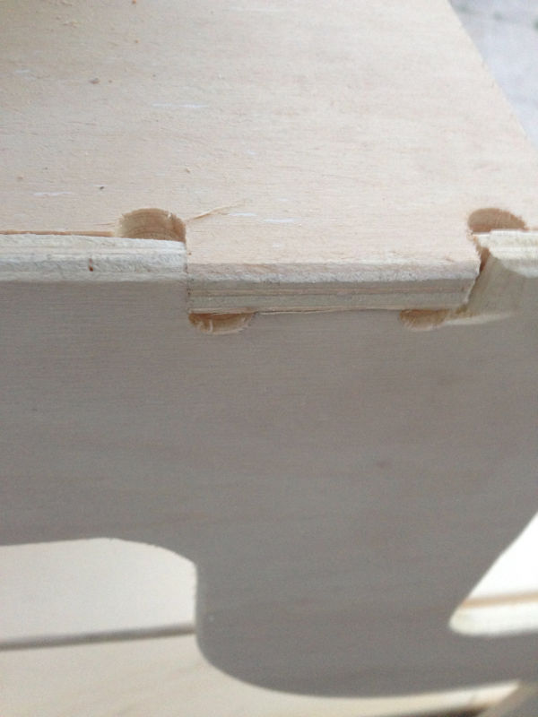
When I had all my pressfit connections ready developed, I had to think about the tool (mill) of the CNC machine. When you think about how the machine would mill a 90° degree corner normally you would always have material left in that corner. To become sure that there is not too much material left in this corners, I uses this dog bone shaped connection wholes in my construction. This takes more material than needed from the joints but with this technique there is no colliding material left in the joints.

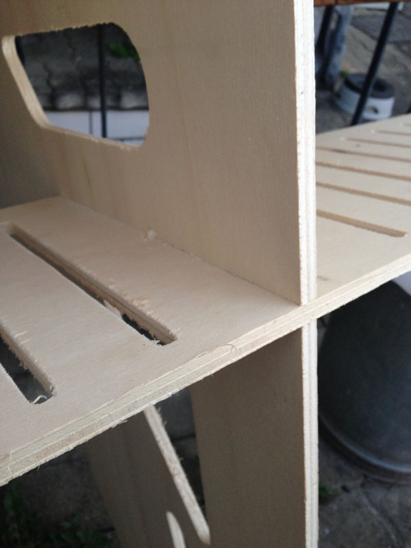
I designed the model with a stair, so the dog can climb the platform on its own. The stairs are also open on the side to have some storage space in it to keep some stuff there. On the platform there are on the top and on the bottom support layer venting holes. Because the whole construction is placed before a heater that is under the window. The venting wholes should enable the warm air to move thought the platform and not blocked under it.

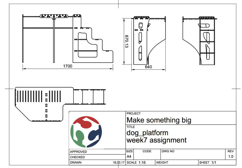
I also used this Fusion to generate this technical construction sheet. This is always helpful when describing other people how the stand should look like and how the dimensions are.
When the model was ready, I generate a sketch on every face I wanted to mill later. The sketches that was generated that way has all the latest forms of the latest body in it. This sketches I exported as dxf files to work with them in Rhino.
At last I used Rhino to layout all my parts on the wood sheet. I imported the dxf files and generate a frame that had the size of the wood sheet. Than I oriented all the parts into the square to that I was sure that everything is fitting on my wood sheet.
When all the parts was placed right I checked them if they all was closed shaped. Because the software of the CNC mill cannot handle files where lines are multiple times over each other. It can happen that when exporting sketches from Fusion that there are lines more than once on the dxf file. Rhino enables you to remove this problem. You can also use it to check if every shape is closed.
The milling process hands on the CNC machine
With my exported cleaned dxf layout in the usb stick I went to the CNC mill and loaded the file into its software.
Prepare the machine before we can start
Milling configuration
| Name | Value |
|---|---|
| Cut depth | 2.7mm |
| Drill diameter | 4.0mm |
| Spindle speed | 18000 |
| Plunge rate | 800 |
| Feed rate | 2000 |
| Spindle direction | CW |
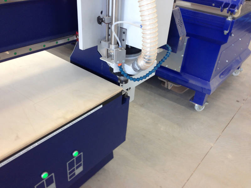
When the dxf files were prepared in rhino and all the lines were connected, they could be loaded into the CNC machine. To prepare the machine Daniele and I moved the sheet of wood onto the CNC mill. The sheet was just the size of the machine. To fix the wood onto the mill it has a vacuum table to hold the wood in place. The table has multiple vacuum zones. Depending on the size of the wood you have to enable the matching vacuum zone on the machine.
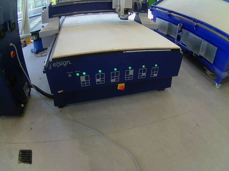

To move the machine head it has a remote control. This control is needed to calibrate the machine and move it into the start position to home the machine before starting the milling process.
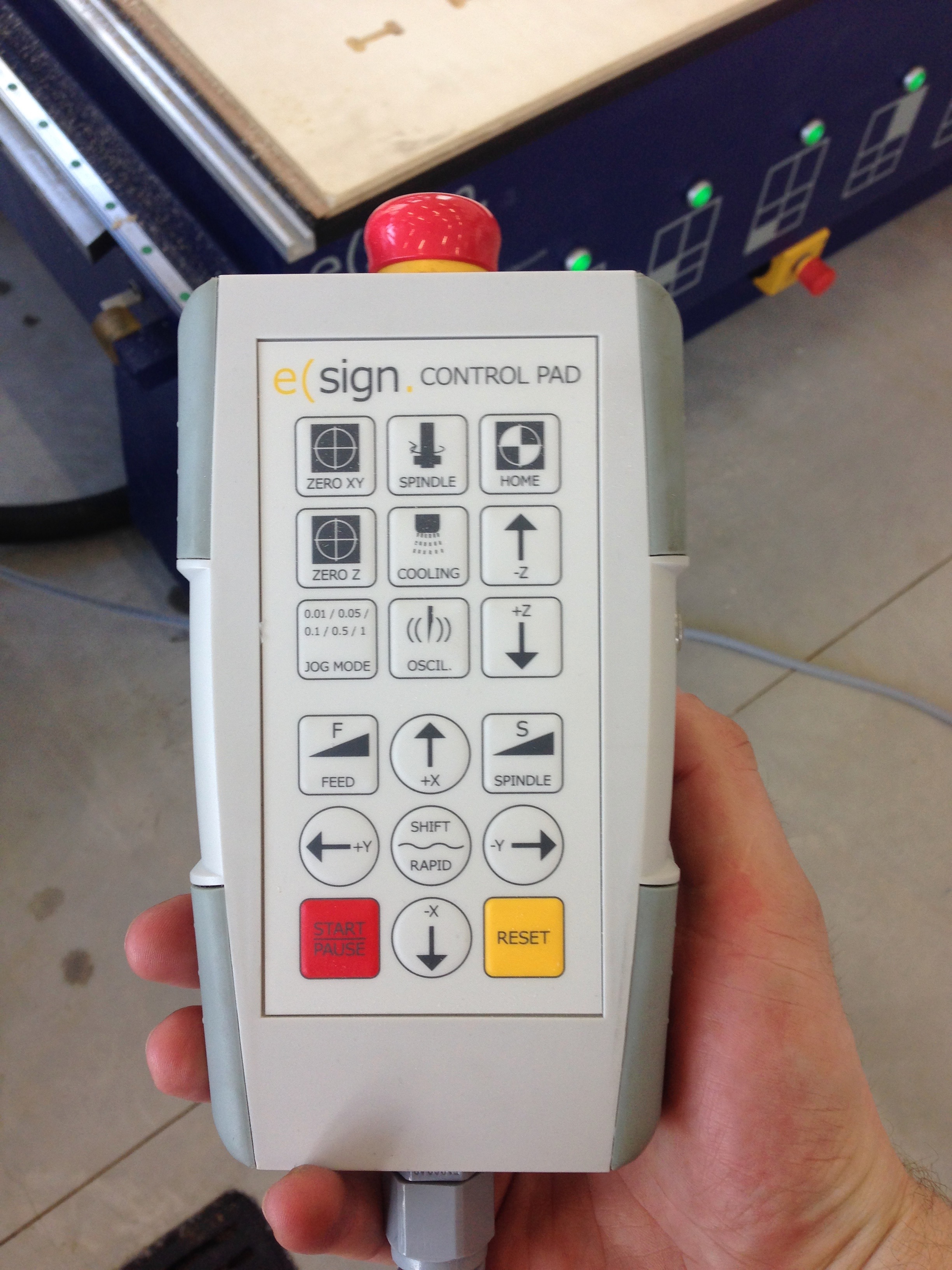
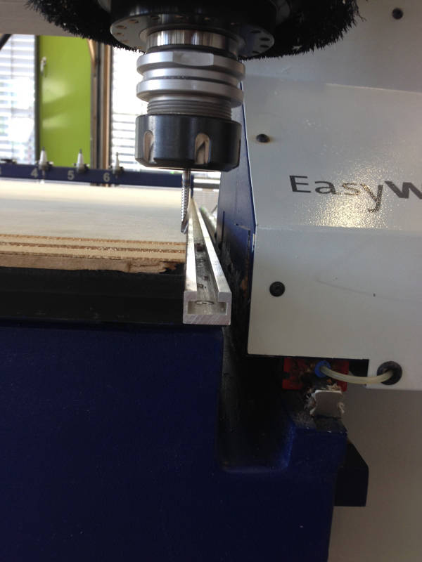
Before I can start the milling process the machine has to be told where it should start. This is because you can use different sizes of wood and thickness. Depending on all this the machine can have different starting points. I used the remote to move the mill on the edge of the sheet of wood. We also used a button that is attached to the machine to set the z height.

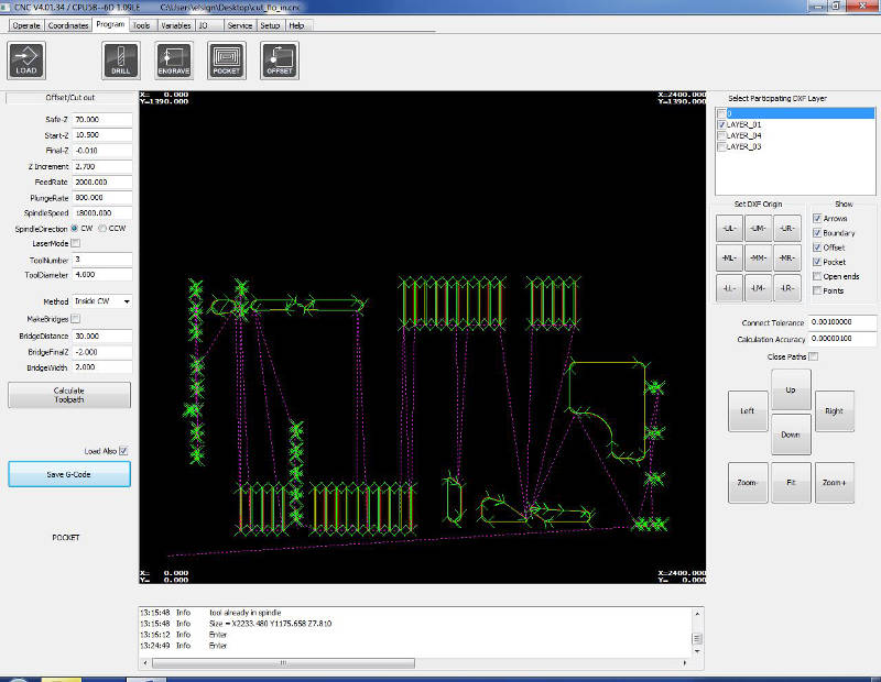
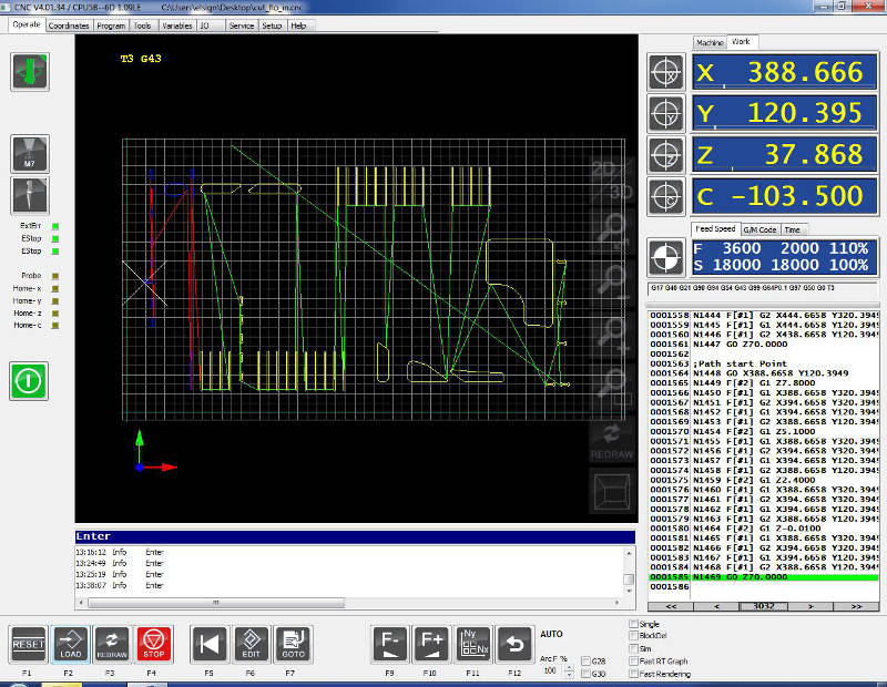
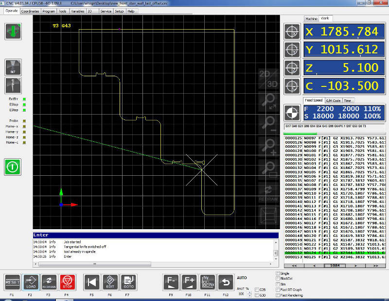
When the machine was homed the milling job can start. The software with the loaded model layout did the rest. All whats left to do is to watch the process and see if anything goes wrong.
The images below shows the software that shows the milling process. It also shows the remaining time, milling speed and the current position of the mill.


This is the video of the milling process.
At the end of the milling process the machine become jammed because the vacuum pipe moved between the moving part of the cnc mill and the frame of it. So we stoped the machine and fixed the jammed pipe.

When the jamming was removed we can start the program where we stoped it. This was able because we only stop and not abort the milling process. Because we watched the process all the time we were able to stop safely the job before the machine was damaging anything.
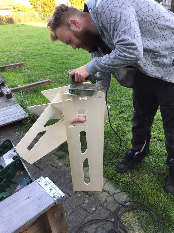
Post process finish it
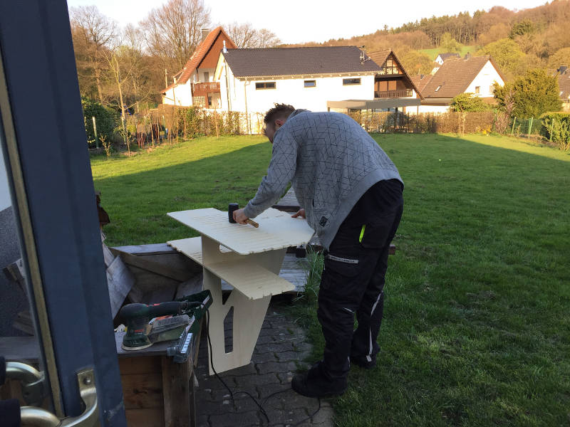
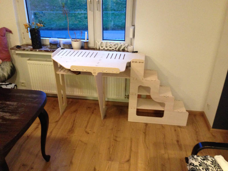
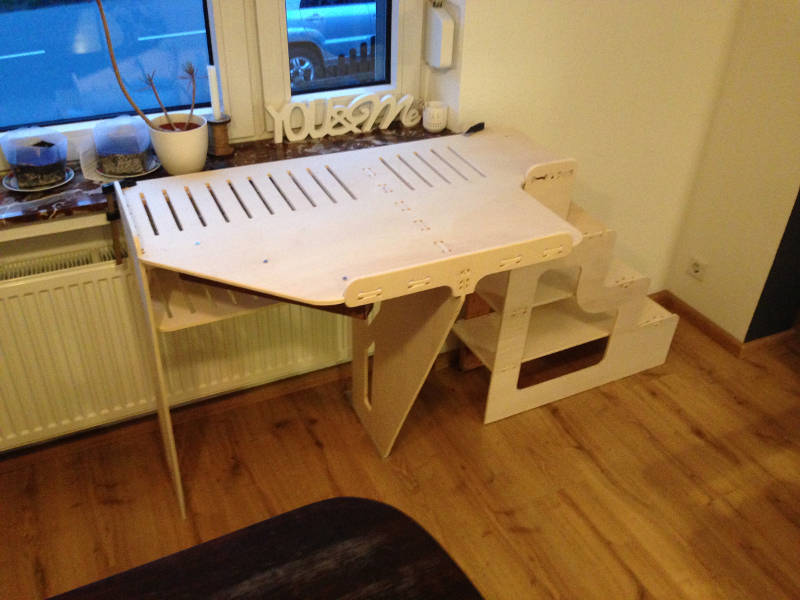
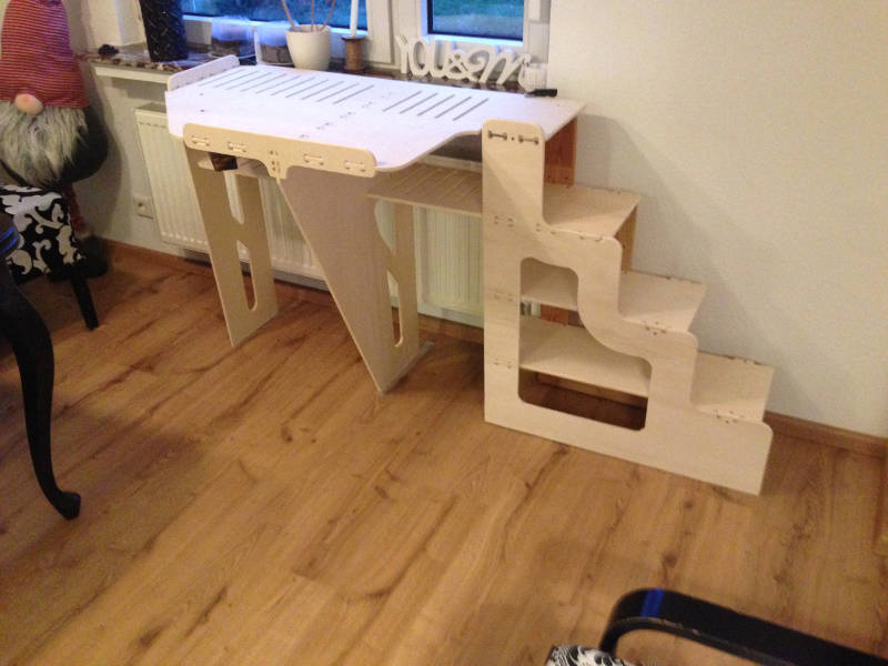
So far so good but after cleaning the CNC machine the parts has to be put together. I also used some sandpaper to break all the remaining sharp edges on the model.
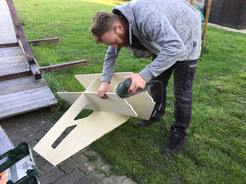
Here you can see the resulting joints I designed in Fusion 360. There are 90° degree corners, some joints where on sheet ended in a surface and also crossing parts that should give the stability on the construction.

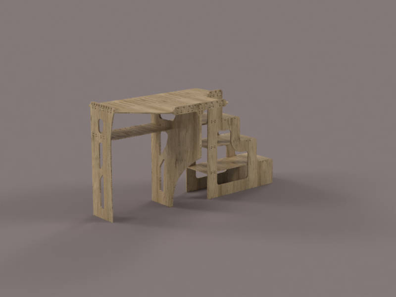
And here is the final result of the model. I'm not sure why but there was an one centimeter space between the window board and the top platform of the model. I used some spacers to fill this gap. I also added some rubber feet unter the model to prevent sliding when the dog jumps onto it.
Download section build yourself
| Fusion file format | download |
| Parts dxf format archive | download |