Searching for tools which software fit my needs
Second week of the academy and we should look at different tools to learn their benefits and their downsides.
What tools did I test look under the hood
CAD tools of my choice third dimension
To get a new option when it comes to CAD I decided to use a tool which I was familiar with and one I didn't know to compare them. I revisit a good friend of mine and also Solidworks that is new to me.
Fusion 360
Fusion 360 is from Autodesk. It's similar with Inventor but it's cloud based. The best advantage that it has in comparison with Inventor is, that it can be installed on my Mac. So I can use it at my Windows workstation at home and on the go on my Macbook.
Solidworks
Solidworks is another CAD software that focus on creating objects in dependency to each other.
Starting with Fusion360 cloud based Mac compatible
I recently started using Fusion360 and enjoyed it very much. Normally a lot of the good CAD software ist for Windows PC only and also all the rest of Autodesk's software. But for whatever reason, they bring Fusion360, an Inventor like software but cloud based, also for OSX.
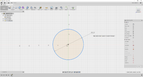
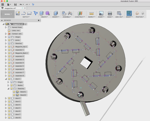
Try to create a magazine mechanism for my remote dog harness. With this idea in mind I created a sketch to get an idea for the dimensions of the magazine.

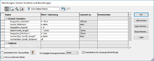
At the moment I am not sure about the mounting and the construction around the magazine, so I did it completely parameterized.
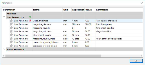
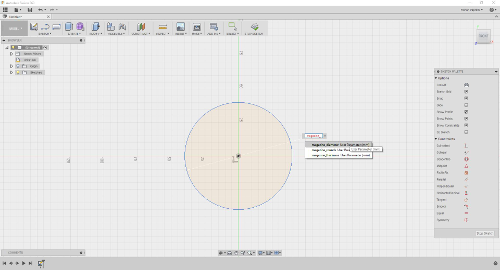
With all the parameter added I used them for the first dimensions. The shortcut "d" triggers the dimension tool. After selecting it you can select an sketch element like the circle and add a value to it. You can use static values or use a named parameter like one I added before. So I add the dimension "magazine_diameter" to the circle.
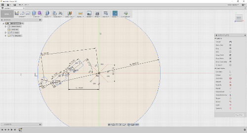
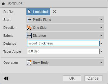
After build up all the necessary forms on the sketch and fully constrained them with the given parameter I was able to extrude the sketch into the third dimension. I also used the parameter in the extrude dialog box to give the material the possibility to change its thickness.
With the first body created, I started a secondary sketch right from the side of a mounting whole on the magazine side body. Then I projected some orientation points from the side plane to design the separators of the magazine pockets. Here I also used all the parameters I added in the First step.
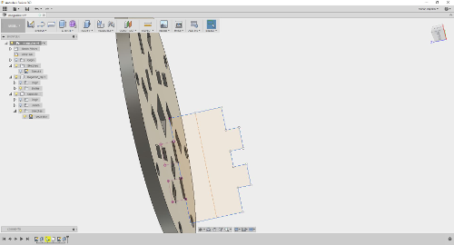


To complete the pockets for in the magazine I added the second half of the side plane. Because the magazine is also variable in width, I first added a offset plane with the half distance of the magazine. This plane I used to mirror the second half. With this trick the other side automatically changes to the correct distance when changing this parameter.
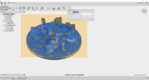

At least I added a door for each pocket so that the magazine input cannot fall out. This part I connected additionally with joints so they can move in the model.


I added the model as STEP and in fusion format to that everyone interested can download it.
Solidworks making solid work???
I never used Solidworks before. When the FabAcademy told me that I'll get a one year license I was interested and wanted to compare Solidworks against Fusion360.
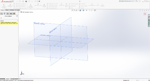

I find out that the design process is similar to Fusion360. Because I am not so familiar with the program it was first hard to find all the options I needed. But when I look into some youtube tutorials it was nearly the same so far.
What about SVG? 2D Vector graphic engine I used
Draftsight
Because we was introduced to it I tried to use Draftsight. Draftsight is a 2D vector based software that os free to use. One noticeable point is that you can create the sketches by command line.
AutoCAD Mechanical
Last but not least I preferred to use AUTOCAD MECHANICAL. It is a powerful 2D and 3D vector based software for professional constructions that is capable to export in a lot of formats.
Work with Draftsight first try, first fail
After installing Draftsight I began my first sketch. I try to draw a disc in the size of 10cm. Inside the disc I had to position the separators for the magazine.
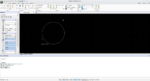
The creation of a circle in Draftsight can be accomplished in two ways. First would be to use the circle tool. The second is to do it by command line. So to draw the circle you can also enter the command: circle
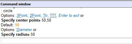
Now the tool asks for the parameter of the circle. So to draw a circle with a diameter of 5cm that is positioned right on the x/y axis you can enter the following commands.
circle <enter>
50,50 <enter>
50 <enter>
I thought I had to calculate the coordinates for the separators because they are placed in a circle. I refreshed my math a little bit. A quick research let me discover the formula to calculate the positions for the origin of the rectangles.
x = cx + r * cos(a)
y = cy + r * sin(a)
Because I wanted to place 8 separators they had to be in an angle of 45 degree. So I calculated the start points for all the rectangles.
x0 = 100.00 = 50 + 50 * cos(0)
y0 =  50.00 = 50 + 50 * sin(0)

x1 =  76.27 = 50 + 50 * cos(45)
y1 =  92.55 = 50 + 50 * sin(45)

x2 =  27.59 = 50 + 50 * cos(90)
y2 =  94.70 = 50 + 50 * sin(90)

x3 =   0.19 = 50 + 50 * cos(135)
y3 =  54.42 = 50 + 50 * sin(135)

x4 =  20.08 = 50 + 50 * cos(180)
y4 =   9.94 = 50 + 50 * sin(180)

x5 =  68.36 = 50 + 50 * cos(225)
y5 =   3.50 = 50 + 50 * sin(225)

x6 =  99.22 = 50 + 50 * cos(270)
y6 =  41.20 = 50 + 50 * sin(270)

x7 =  83.35 = 50 + 50 * cos(315)
y7 =  87.26 = 50 + 50 * sin(315)

x8 =  35.82 = 50 + 50 * cos(360)
y8 =  97.95 = 50 + 50 * sin(360)
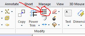
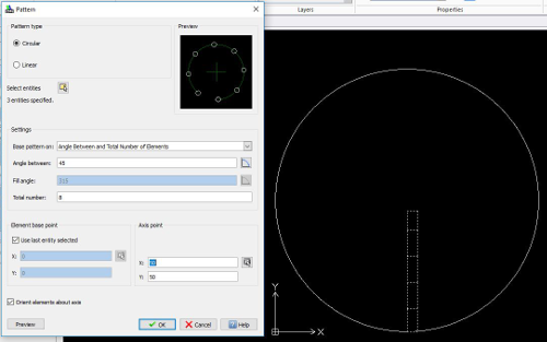
Nice try but after I've done all the math, I saw that Draftsight has an option for drawing pattern. So all the calculations wasn't necessary. The following image show the pattern functionality. Here you can choose between a linear style copy pattern or a polar style pattern. I chose the polar pattern set the circle as the center point for the pattern and choose the pattern angle to be 45 degree.
After adding the separators and also the numbers for engraving the results looks as following.
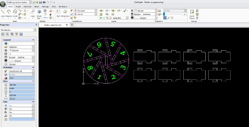
As you can see, I also added the separators to the design. I designed one separator and multiply it also with the pattern functionality. This time I used the linear pattern option so I have all the parts in one sketch to for the construction.
AutoCad Mechanical another Autodesk software
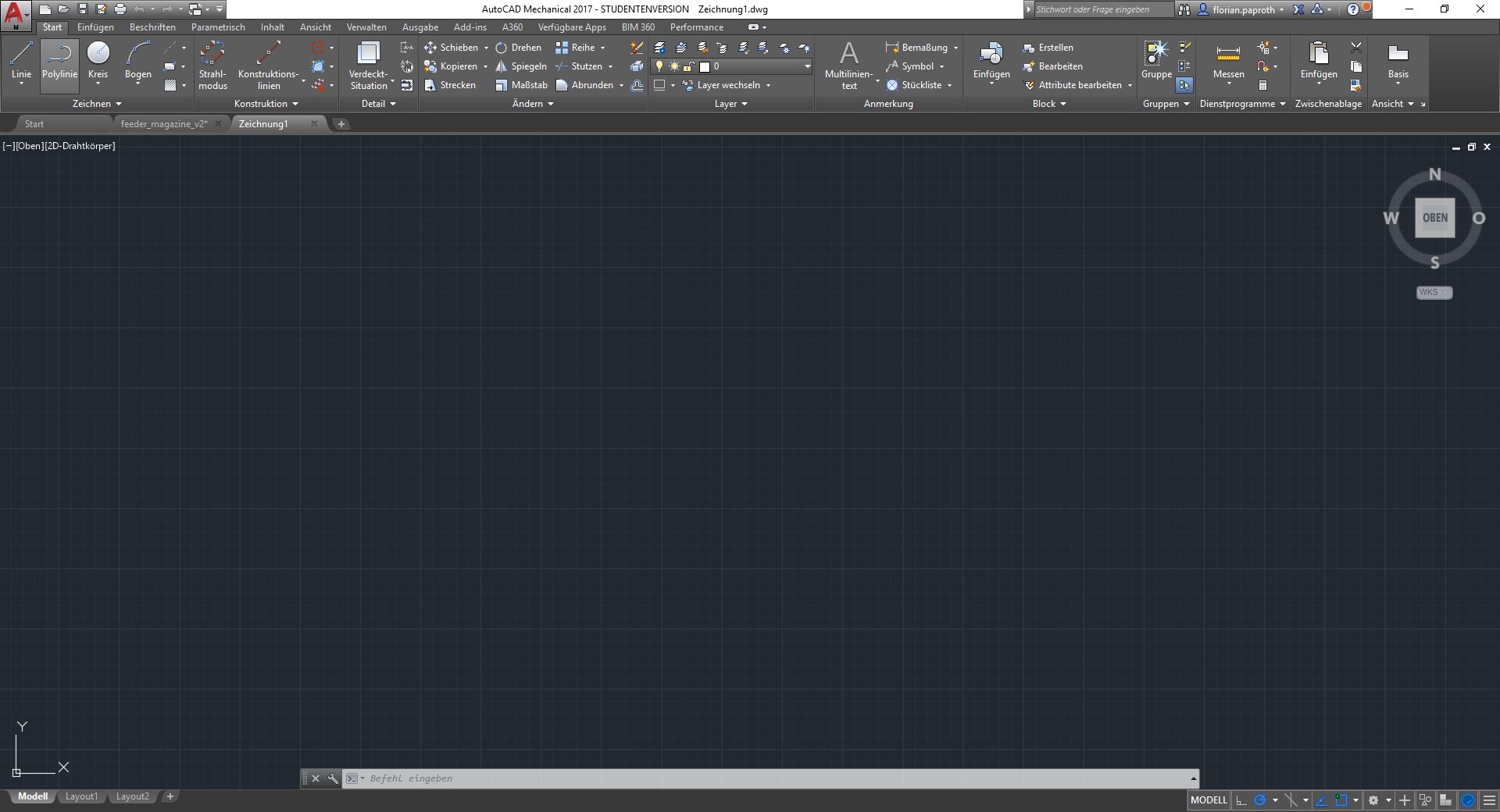
Using AutoCAD Mechanical was a blast in the 2D environment. It looks very sorted and has a lot of tools to help developing vector graphics. It's ui remembers on the Autodesk companion app Fusion 360.
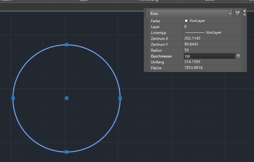
Something I like on AutoCad Mechanical very much is the strict parameter the elements are bind to. For example when drawing a circle you can mark it and then click the circle again. A for detail window than appear and here you can see everything this circle is all about. Important is here the diameter. Here you also get some side information about the space the circle takes. More important should be the x / y placement.
For a parametric design it is also able like in Fusion to add dimensions to to forms that are dependent from each other. Dimensions are also a good way to display dimensions of forms easy in the sketch. Double click the added parameter enables you to change the value. All dependent elements are than updated as well.

More and more thing I find are similar in all the tools. For example the pattern tool is something I found in almost all the tested tools but is alway very helpful to multiply things or to draw them in a circle pattern.

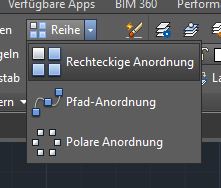
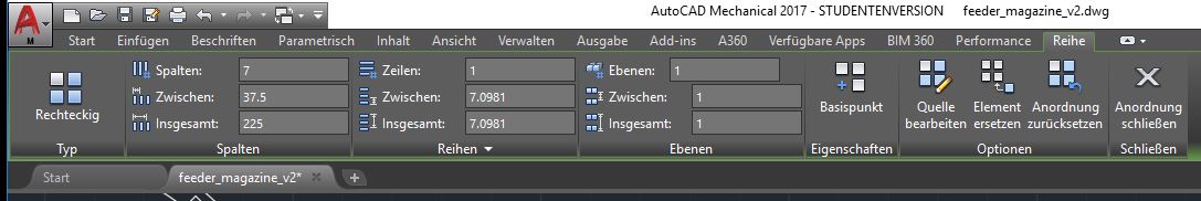

Here I used the pattern tool to multiply a pressfit structure that should bend around the circle to form a magazine.
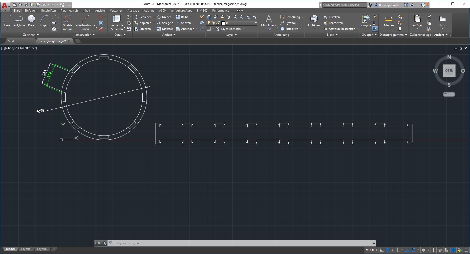
This is a first test to use AutoCad Mechanical to build a laser cut magazine and test this pressfit structure for my final project.
Download section magazine files
| Fusion 360 magazine (f3d) | download |
| Solid works (step) | download |
| Draftsight (svg) | download |
| AutoCad Mechanical (dwg) | download |