Input Devices reading sensors
Revisit the breakout board using FloKit again
In week 10 I build a breakout board for my output devices week assignment. This week I will reuse this board and want to continue with the work I've done this week. You can read about the work to come to this starting point.
Build a fan speed monitor
PWM pulsing for fan speed
The fan is driven by a 12V input that comes from my desc power supply. Then the fan I am using is a four cable fan that comes with additional cables for speed control and for telling its rotation per minute. The speed is controlled by a PWM (pulse width modulation) signal and the rpm cable toggles the voltage for every rotation it does.
So at first I will first use PWM to manipulate the fan speed. PWM stand for (pulse width modulation) and is the technique to change a signal from high to low on a specific frequency. It is either be used so slow down, dimm or lower the voltage that a device recognize. It also can be used to control devices that read a PWM signal like a servo motor.

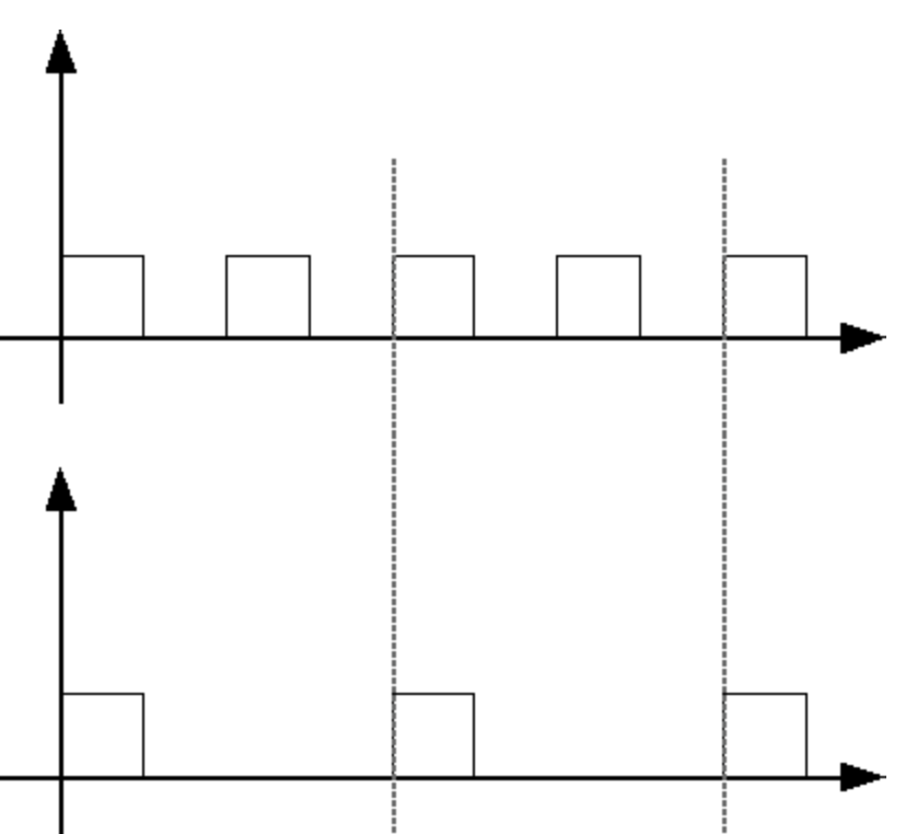
The image shows the line chart of a PWM signal programmed with an Arduino analogWrite(0-255); command to control a PWM output pin.
Programming in C PWM in Atmel Studio
In Atmel Studio there is of course also a way to control the PWM output pins of an ATmega328 microcontroller. Here it is necessary to add some more steps as in the Arduino environment. First you have to enable fast PWM mode. For this consider the chapter 15.6.1 Compare Output Mode and Waveform Generation in the data sheet or use the PWM initialization part in my code.
Fan speed look the rising edges
PWM is used to set the speed on the fan but to read the speed of it I had to use a mechanism in the ATmega where it is able to detect the rising edges of an external signal. to do so it is also necessary to initialize some registers to enable this.
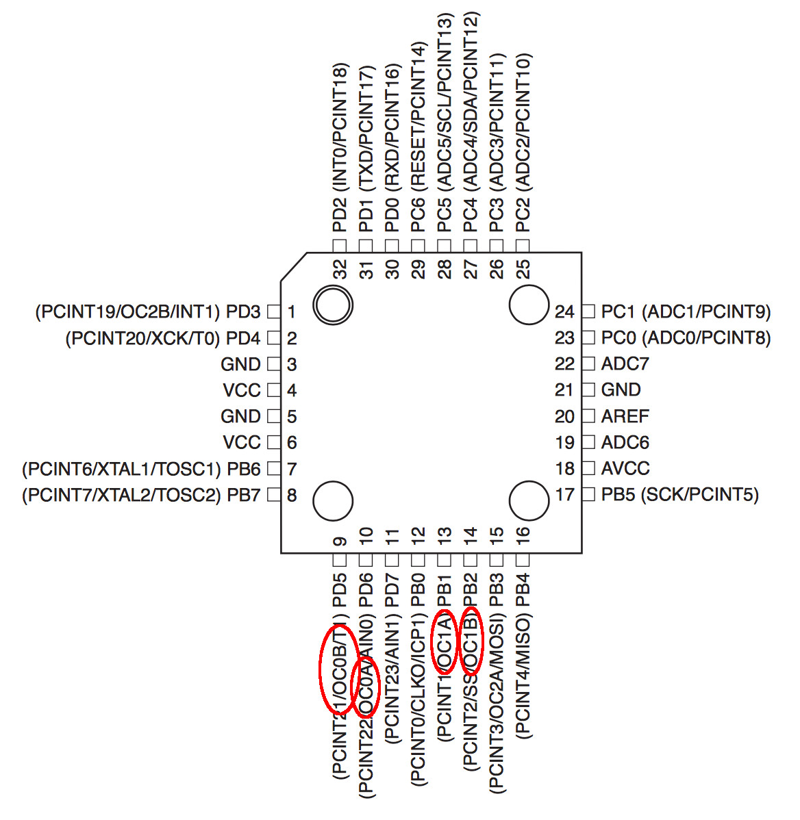
There are four pwm pins on two separated timer registers that can be used for deliver a pwm signal.
/**
 * Initialize PWM on pin PB3
 */
DDRB |= _BV(PB3);

TCCR2A=0;   //reset
TCCR2A |= _BV(WGM21) | _BV(WGM20); // set fast PWM Mode
TCCR2A |= _BV(COM2A1) | _BV(COM2B1); //set non-inverting mode for both OC2A and OC2B.
TCCR2B |= _BV(CS21); // set prescaler to 8 and starts PWM

OCR2A = pwm;    // Set the PWM
To enable the output signal for this I enable it with the command . There is a macro _BV that help setting the values for the data register of the microcontroller. _BV stand for bit value.
After enable the pin for output ew handle the TCCR2 or Timer/Counter Control Register 2. TCCR2A is good for short time delays because, its prescaler has a number of options. It can run in
| MODE | WGM21 | WGM20 | DESCRIPTION |
|---|---|---|---|
| 0 | 0 | 0 | Normal |
| 1 | 0 | 1 | PWM Phase Corrected |
| 2 | 1 | 0 | CTC |
| 3 | 1 | 1 | Fast PWM |
In the Timer/Counter Control Register 2 I set the prescaler of the of timer to 8 Bit.
The prescaler can slow down the clock. Normally there are steps possible like 1, 8, 64 ,256 or 1024.
Than later in my main loop or other functions the pwm frequency cam be set with OCR2A = <pwm value>;.
Reading the fan speed
To get the speed of the fan I enable the a Interruption mode in the microcontroller to react on external interrupts. To see how this is done consider 7.7 Reset and Interrupt Handling in the data sheet or use my code example.
I want to enable the external interrupt registration. So I enable it with updating the register EIMSK and set it bit for INT0. Before that I configure the mechanism because I want it to trigger on rising edges of the external signal. This can be accomplished with updatating another register. EICRA |= _BV(ISC01) | _BV(ISC00);.
When this is set up every time the microcontroller detects a rising edge on this pin it will trigger the callback ISR (INT0_vect){} that I used to count the rotations of the fan.
/*
 * Fan_control.c
 *
 * Created: 02.05.2017 23:26:54
 * Author : Florian Paproth
 */

#include "main.h"

uchar f_timer_tick;
uint NbTopsFan;
uint8_t pwm = 0x00;

ISR(TIMER0_OVF_vect) // deprecated: SIGNAL(SIG_OVERFLOW0)
{
    f_timer_tick = 1;   // incrementing the timer count variable
}

ISR (INT0_vect)     // Interrupt when getting rising edge on input pin
{
    NbTopsFan ++;   // count the rpm high signals
}

// Initialization method for ATmega328 and software library
void init(void){
    // ------------------interrupt init----------------------------------------
    DDRD &= ~(1<<PD2);
    PORTD = (1<<PD2);

    // Interruption modes
    // ISC01 | ISC00
    //     0 | 1 Any logical change on INT0 generates an interrupt request.
    //     1 | 0 The falling edge of INT0 generates an interrupt request.
    //     1 | 1 The rising edge of INT0 generates an interrupt request.
    EICRA |= _BV(ISC01) | _BV(ISC00); // set INT0 to trigger on rising edge

    EIMSK |= _BV(INT0);     // Turns on INT0 interruption

    // ---------PWM init--------------------------------------------------

    /**
     * Initialize PWM on pin PB3
     */
    DDRB |= _BV(PB3);

    TCCR2A=0;   //reset
    TCCR2A |= _BV(WGM21) | _BV(WGM20); // set fast PWM Mode
    TCCR2A |= _BV(COM2A1) | _BV(COM2B1); //set non-inverting mode for both OC2A and OC2B.
    TCCR2B |= _BV(CS21); // set prescaler to 8 and starts PWM

    OCR2A = pwm;    // Set the PWM

    // ---------PWM init end--------------------------------------------------

    DDRC |= (0 << DDC0);    // using A3 as button input

    TCCR0B |= _BV(CS02);      //divide by 256 * 256
    TIMSK0 = _BV(TOIE0);      //enable timer interrupt overflow

    timerinit();
    sei();

    lcdInit();  // Initialize the LCD

    timeradd( updaterpm, SECONDS( 1 ) );
}

void updaterpm(void){
    char Buffer[10]; // in diesem {} lokal
    char Buffer2[10]; // in diesem {} lokal

    itoa( pwm, Buffer, 10 );
    itoa( calcRPM(), Buffer2, 10 );

    lcd_clear();
    lcd_home();
    lcd_string( strcat(Buffer , " pwm") );
    lcd_setcursor( 0, 2 );
    lcd_string( strcat(Buffer2 , " rpm") );

    timeradd( updaterpm, SECONDS( 1 ) );    // Recall the function in 1 Second
}

uint calcRPM(){         // Calculate the RPM
    NbTopsFan = 0;      //Set NbTops to 0 ready for calculations
    _delay_ms(1000);    // wait for a second
    return(NbTopsFan / 8);  // count the rising edged and report
}

void whiteButtonPressed(){
    pwm = 0xff;
    OCR2A = pwm;    // Set the pwm
}

void redButtonPressed(){
    pwm = 0x00;
    OCR2A = pwm;    // Set the pwm
}

int main(void){
    init();         // Initialize the I/O

    while(1){       // main loop
        if( f_timer_tick ){
            f_timer_tick = 0;
            timertick();
        }

        if (!WHITE_BUTTON_PRESSED){
            whiteButtonPressed();
        }

        if (!RED_BUTTON_PRESSED){
            redButtonPressed();
        }
    }

    return 0;
}
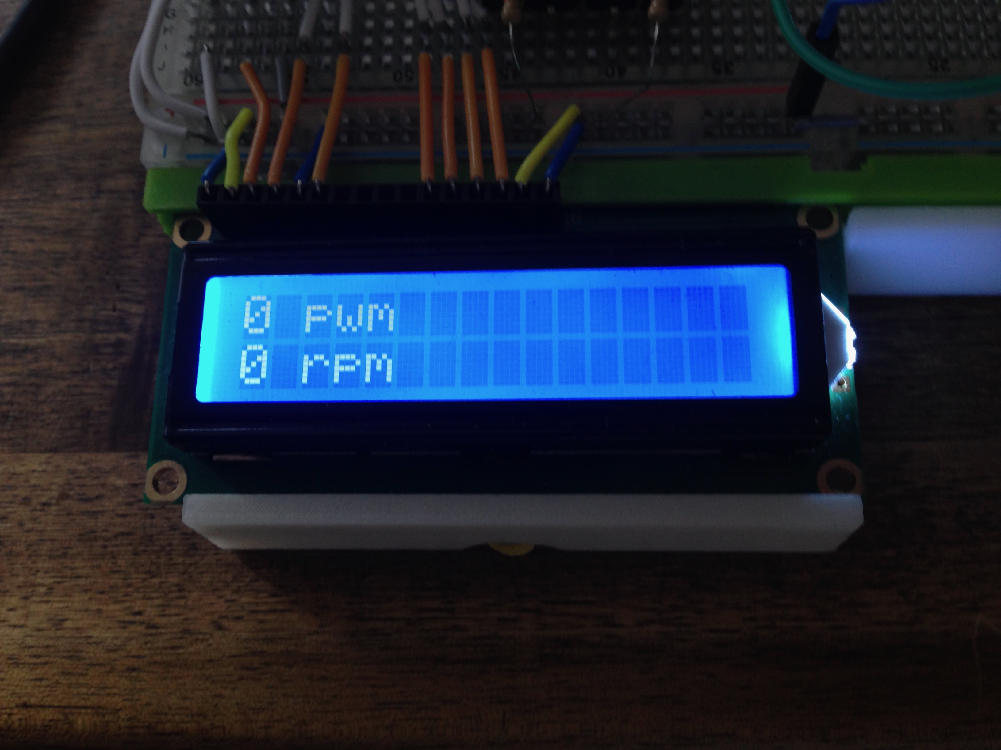
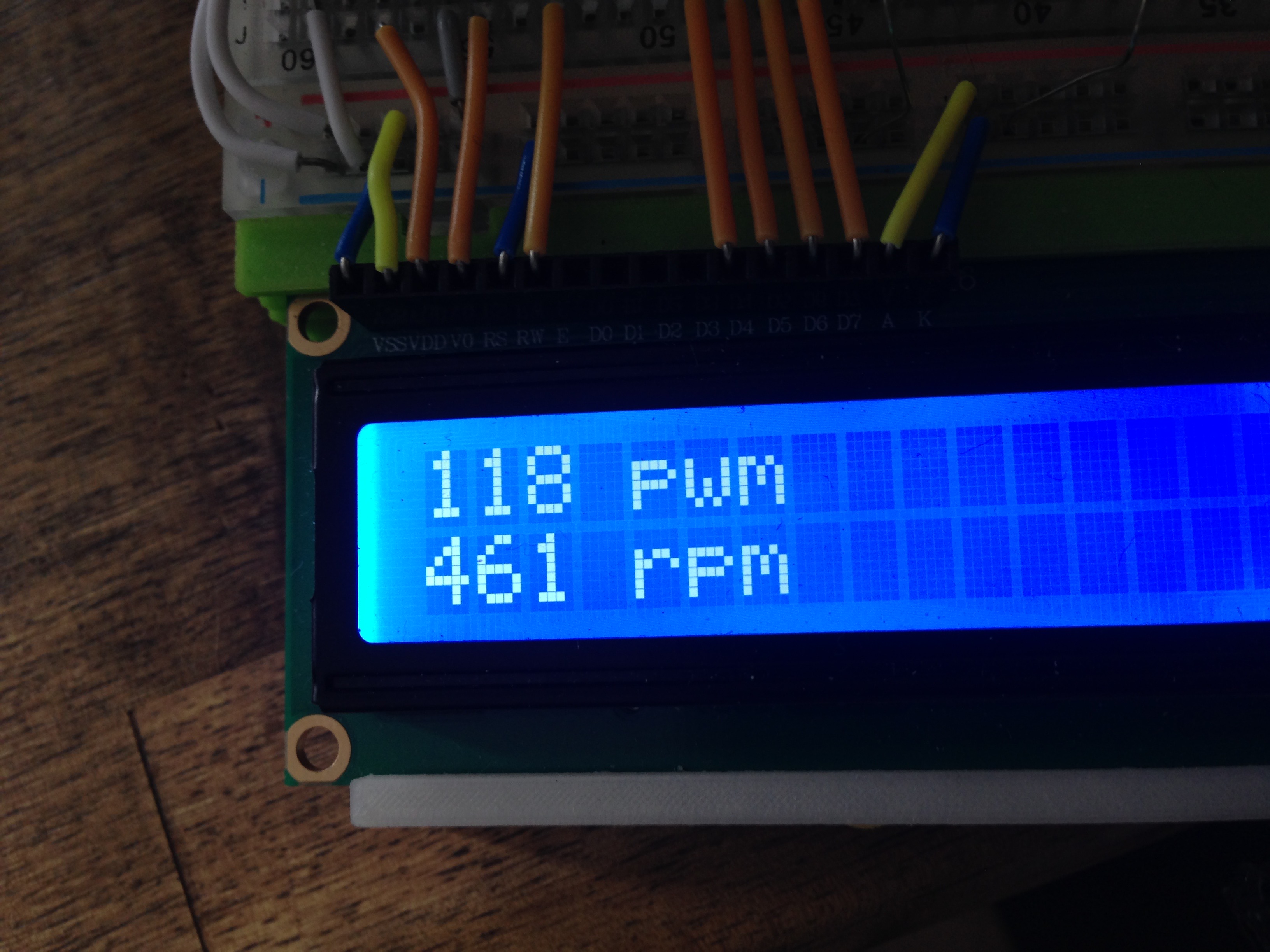
The rest of the code is some controlling to set the fan in to two modes to demonstrate the capability to control the fan. The red button slows the fan down to its minimum and the white button speed the fan up. I also use the display to give a feedback of the rotation per minute of the fan.
In the download below there are the project files to build a fan rpm control on your own.
Download section stuff to download
| FanRPM project (Atmel Studio) | download |