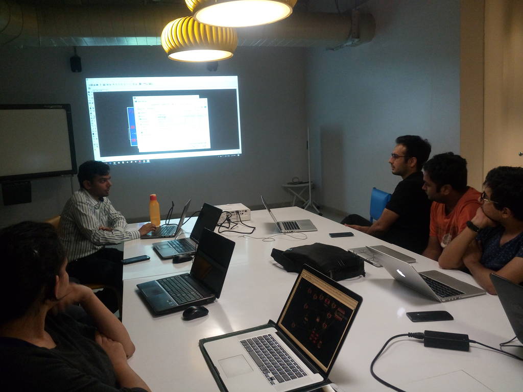
Group discussion and knowledge sharing. Learning Eagle
On a next day itself we had a group discussion and knowledge sharing session where I learned Eagle. Our colleagues explained me about eagle and we all had hands on practice for first day
Downloading and importing fab library within Eagle
Library is a set of components which I can use within my schematic. Libraries can be imported and used or if required we can also create our own library
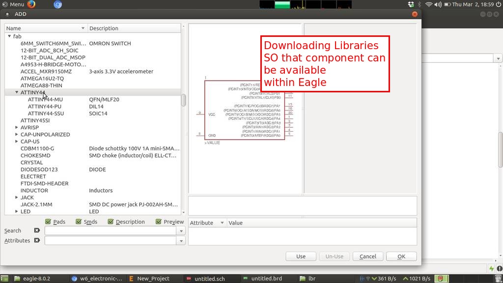
Imported the ATTINY 44

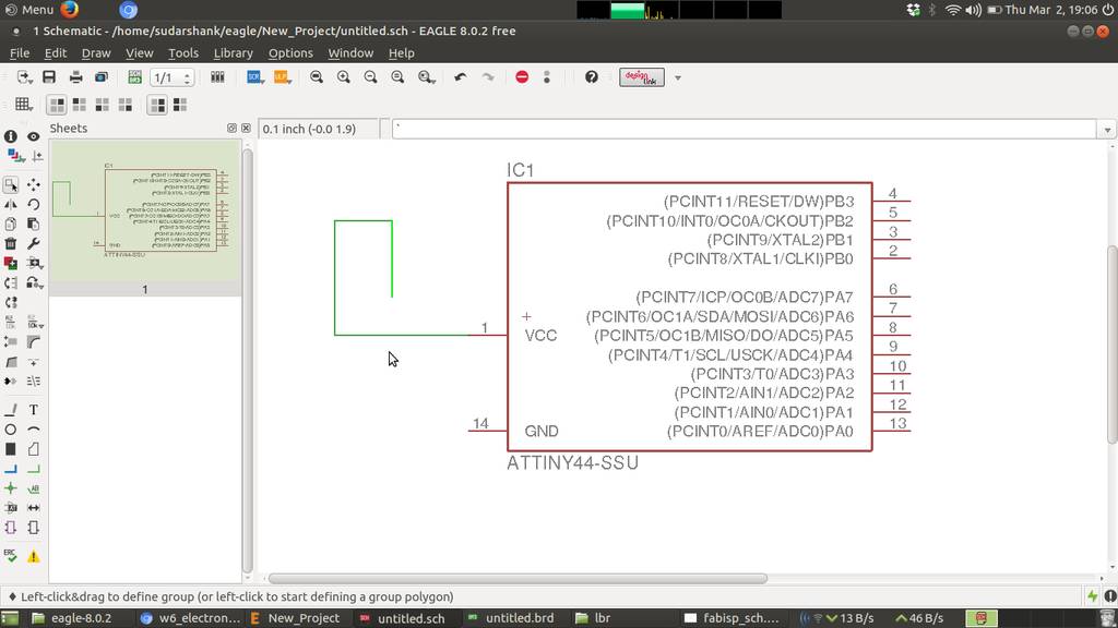
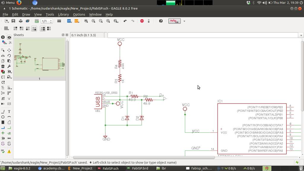
Connecting components to form schematic
That green line is called as a net. Which connects one component to another component. Its labelled as VCC. To label it do a right click and select Name. Provide a name and then again right click and select label. Place a label appropriately
Connecting things using reference label
Net with same labels virtually connects with each other. For example in this case VCC of ATTINY44 will connect with VCC of USB. This is how we can connect using references. Using this technique we can make this design modular and move a part of it to another page to make it neat and clean
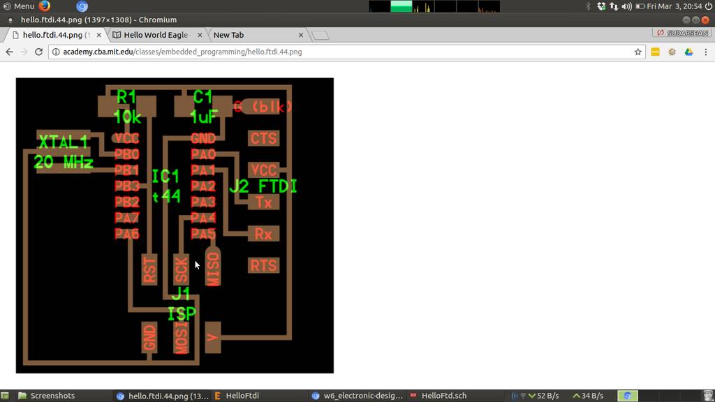
Hello ftdi board for reference
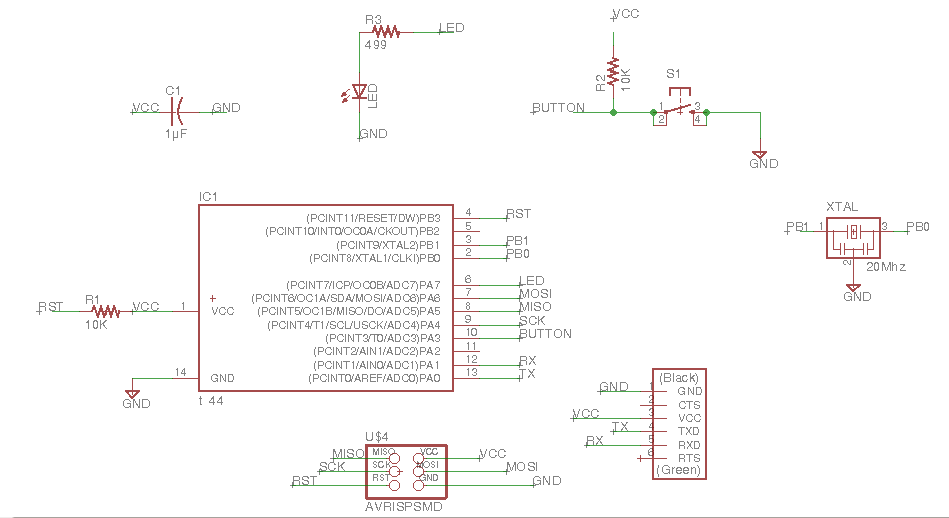
Schematic WIP
Imported components required for hello ftdi board
- ATTINY44
- 6 pin connector
- LED
- Capacitor
- Resonator
- Resistors
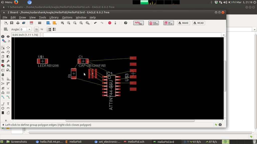
Repositioning compoenents within board layout
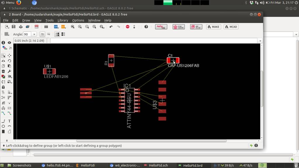
Repositioning again
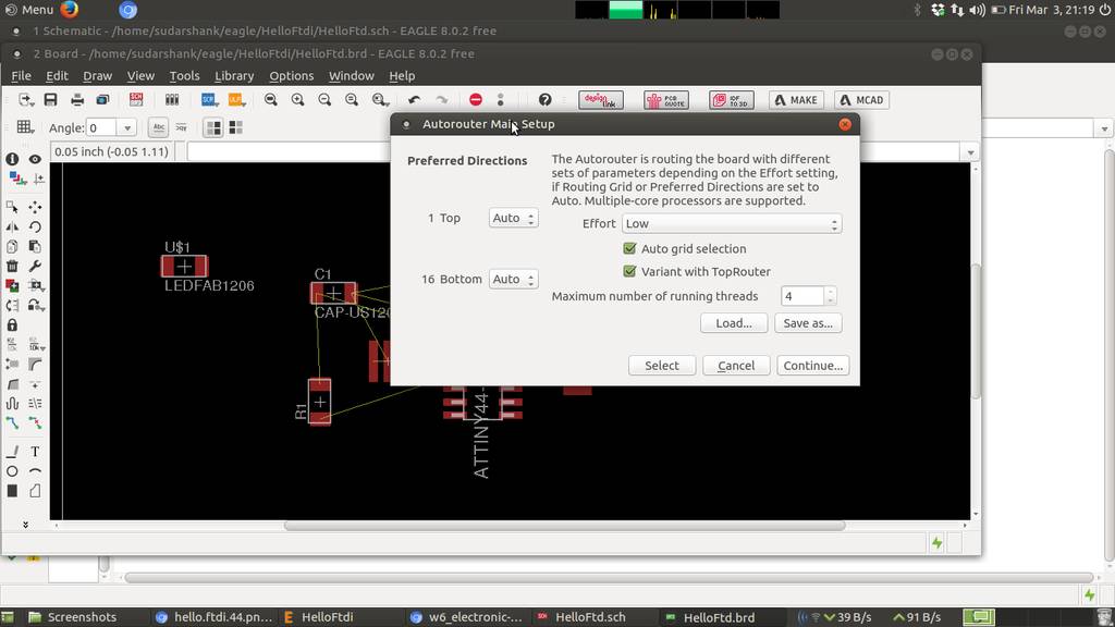
Generating traces using autorouting
Auto routing creates traces algorithmically and try to connect all of the traces to complete this circuit
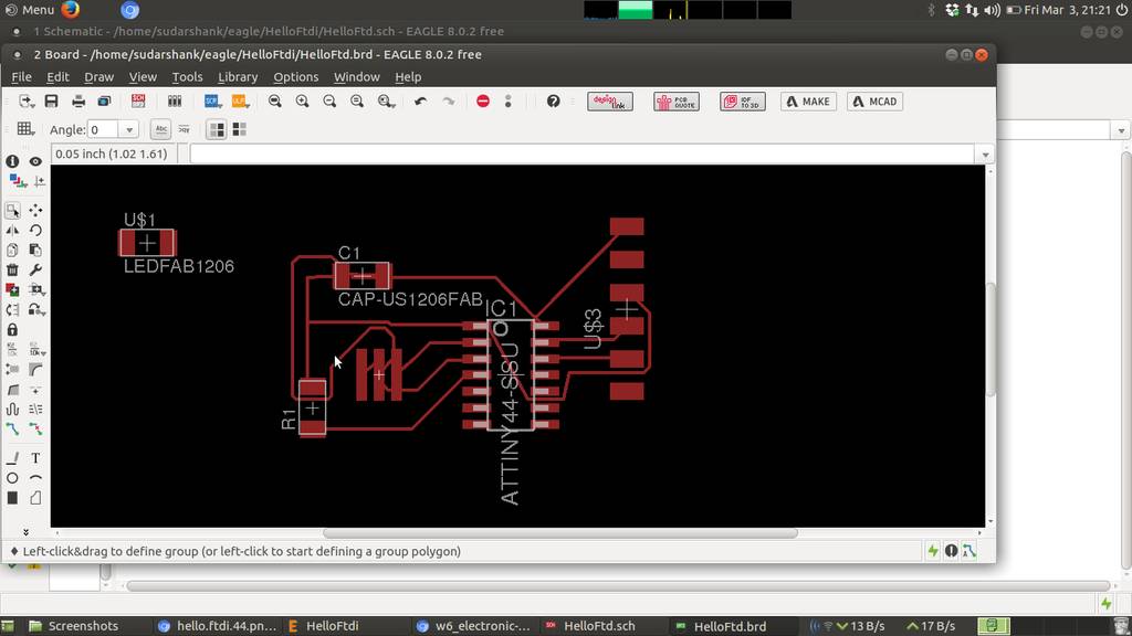
Traces generated using auto routing
Finally LED and switch is connected
Design Rules Check for Eagle CAD
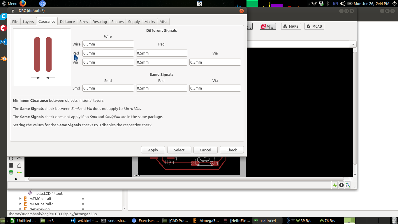
For example if milling bit is of size 0.5mm then traces should be defined with atleast 0.5mm clerance. Otherwise you may end up with very thin traces or else sometimes traces will vanish
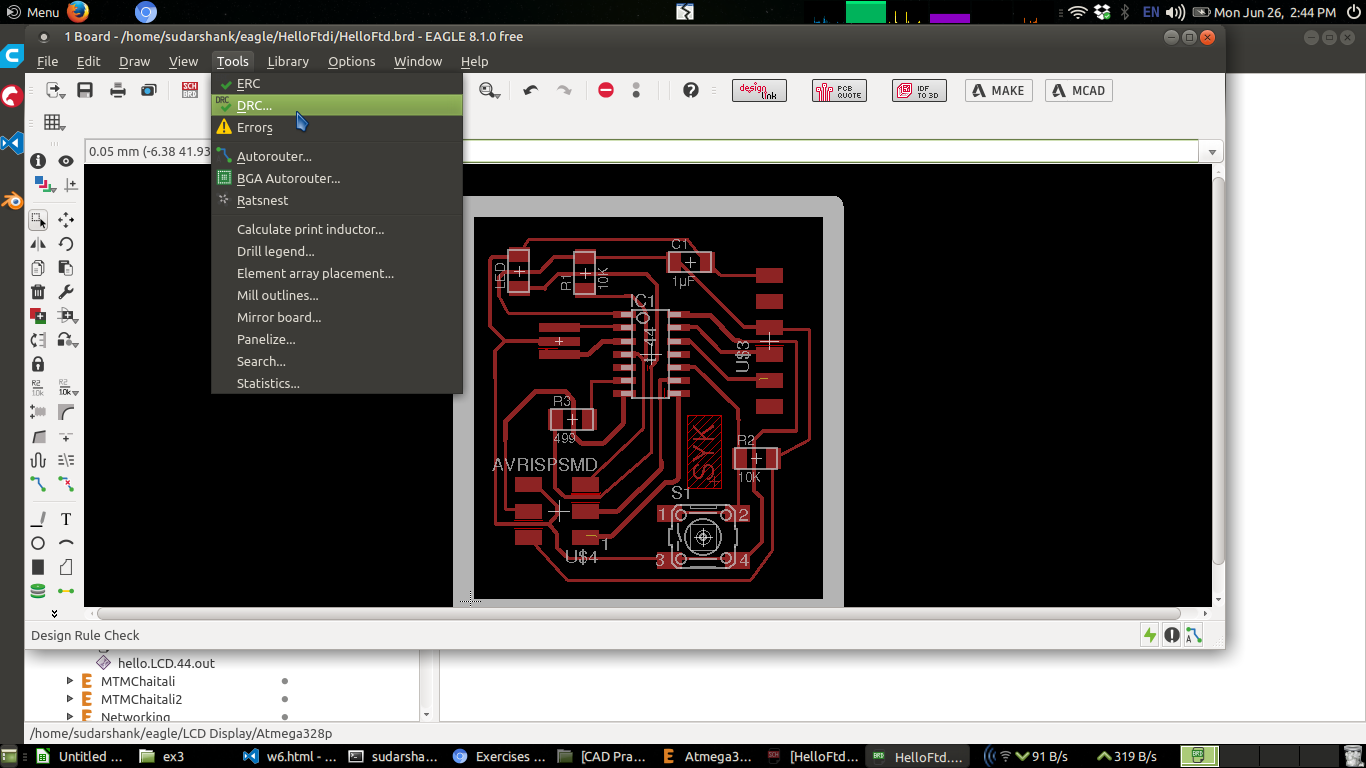
Design rules can be set in eagle cad under menu Tools > DRC
Tools > DRC
Clearance 0.5mm set
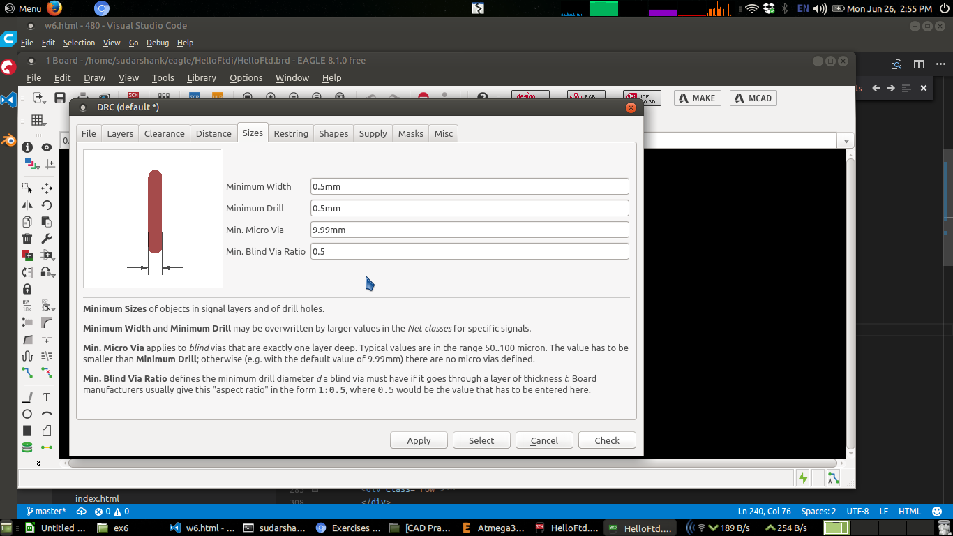
Trace width set minimum 0.5 mm for milling
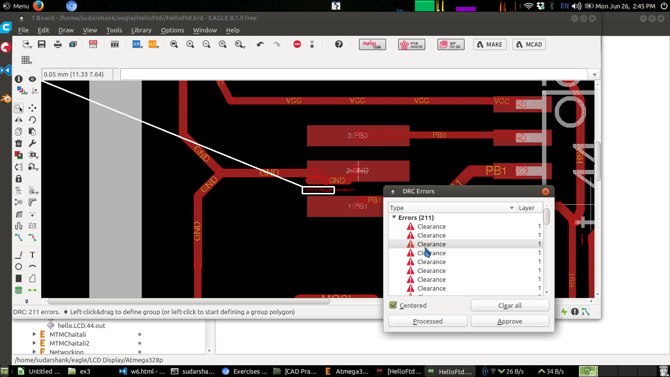
Click on Check
Auto routing will also take care of these design rules you have set and will always follow design rules. You may not get 100% autorouting success when you set design rules.
DRC check showing areas violating DRC
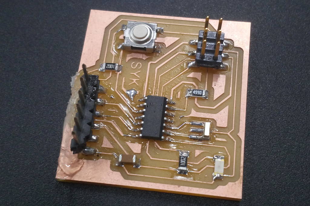
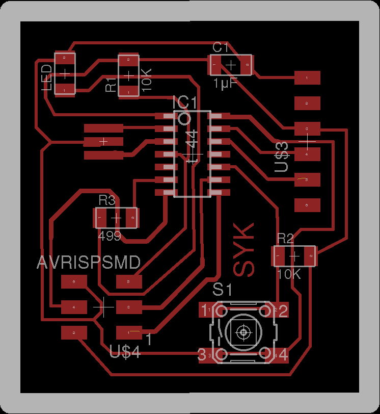
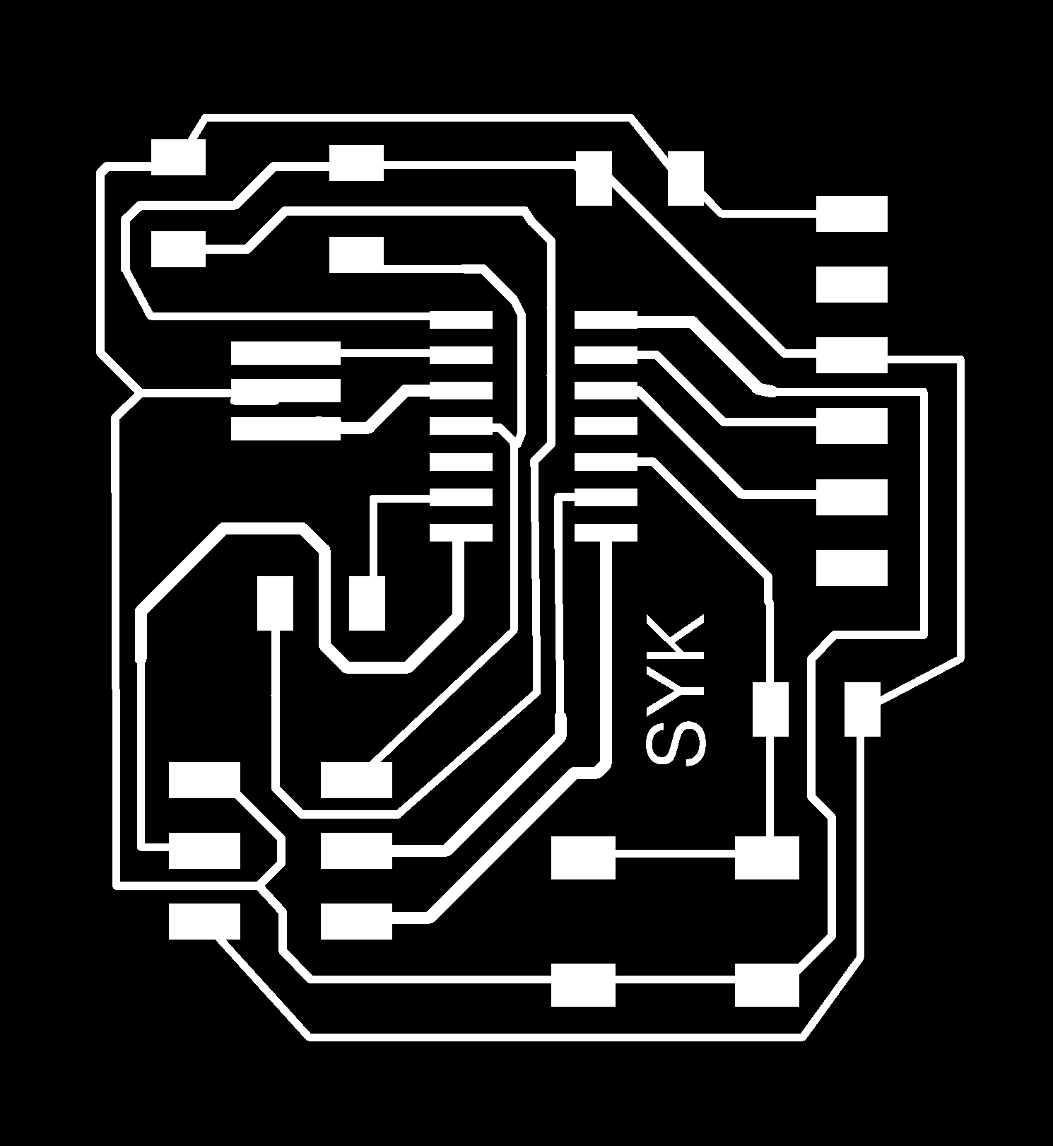
Final Board Traces
Board Cutout

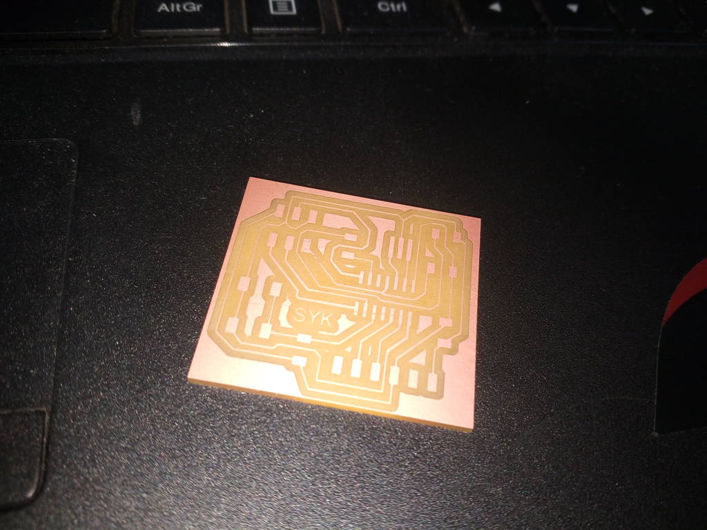
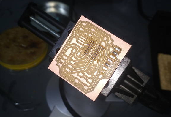
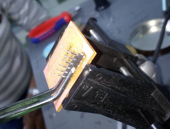
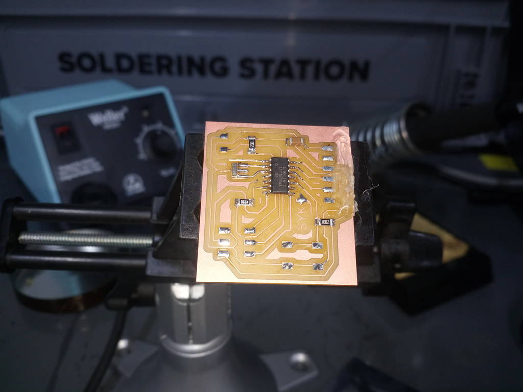
Final fabricated board