Working with LibreCAD
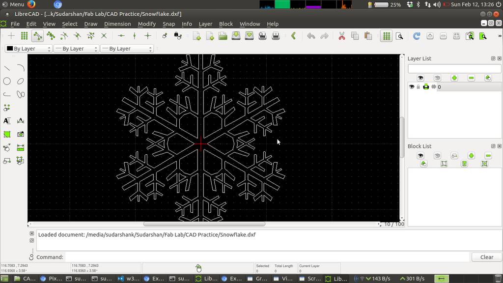
Making a snowflake on Librecad
Following commands used- Line : Two point line
- Scale : Which scales selected object with reference point which we define [Menu : Modify -> Scale]
- Move : Moves selected objects using reference point [Menu : Modify -> Move]
- Rotate : Rotates selected objects from reference point [Menu : Modify -> Rotate]
- Trim : It trims line intersected by another line [Menu : Modify -> Trim]

LibreCAD Move, Rotate, Copy
I found it very useful where LibreCAD provides options to output multiple copies. Its actually an array which you can generate using these options
- Delete Original : Remove original objects and Move / Rotates
- Keep Original : Keeps original objects and Copy / Rotates
- Multiple Copies : Creates Cartesian array in case of Copy and creates polar array in case of rotate

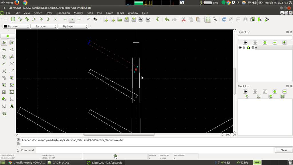
Created initial structure at 60 degree apart
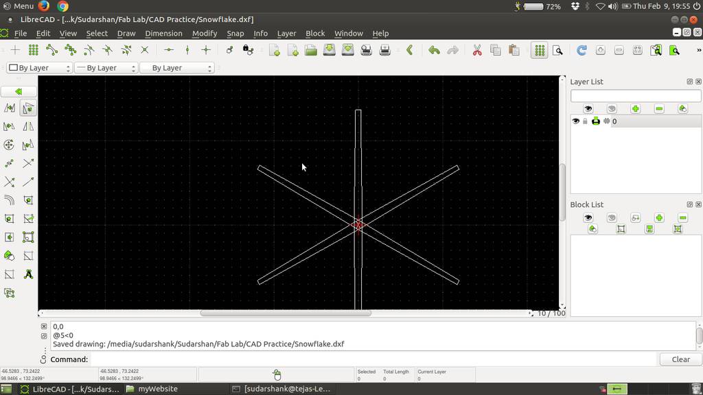
Created line at a distance 20 mm from center
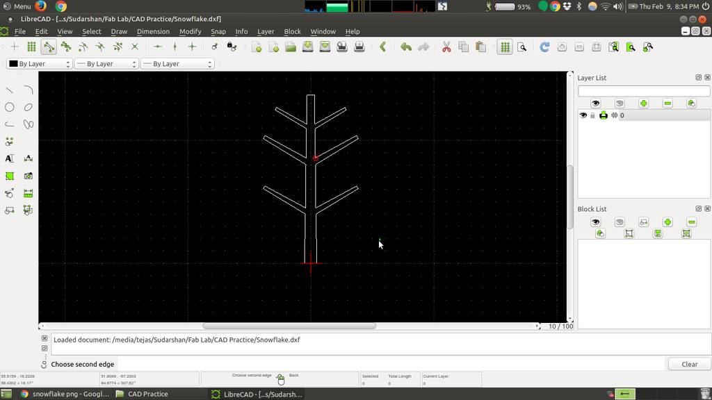
Created leaf geometry and rotated
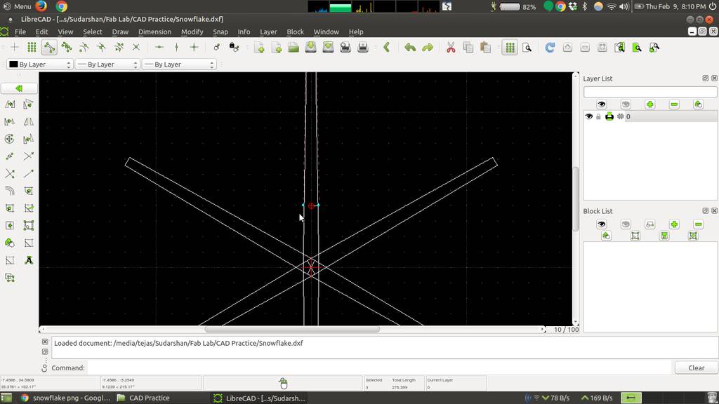
Copied geometry using copy tool
Geometries are scaled and trimmed
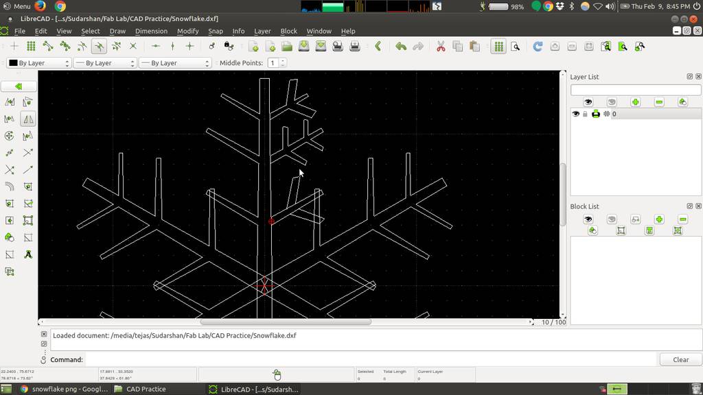
Rotate with multiple copies
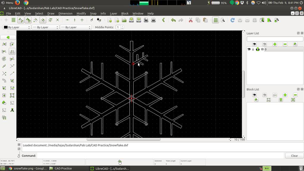
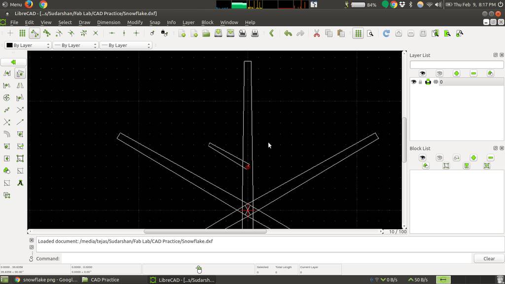
Using trim tool to trim intersections
Final Snowflake using LibreCAD
Exploring and working with Solidworks
Solidworks I found really easy and user friendly to work with. Obviously because of proprietary software and huge team of exprts involved in developement of Solidworks
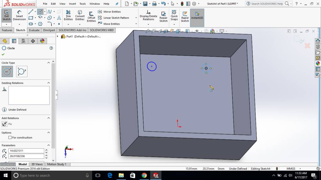
Working with Sketch in Solidworks
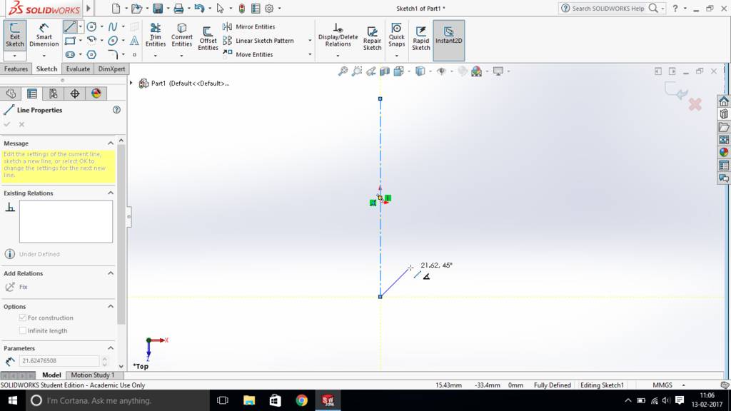
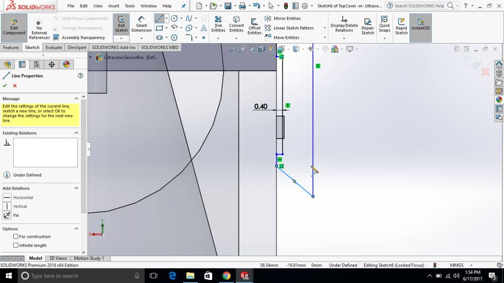
Drawing lines and apply constraints
Sketcher in solidworks I found that it can automatically puts constraints as I draw. Those green symbols in screenshot is a constraints applied for current entities

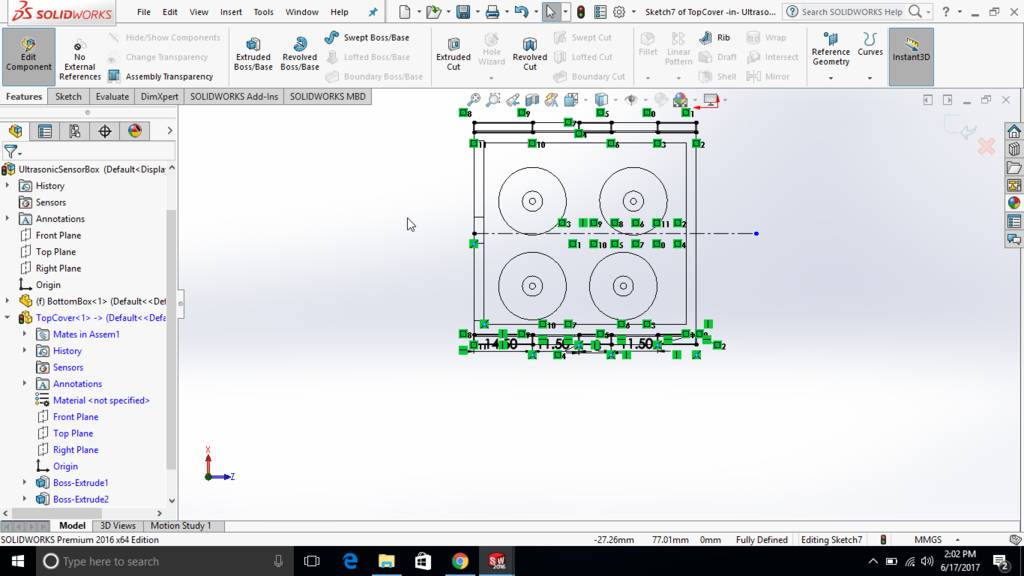
Fillets, Trims, Dimensioning in sketch mode

Converting 2d sketch into 3d solid using extrude command

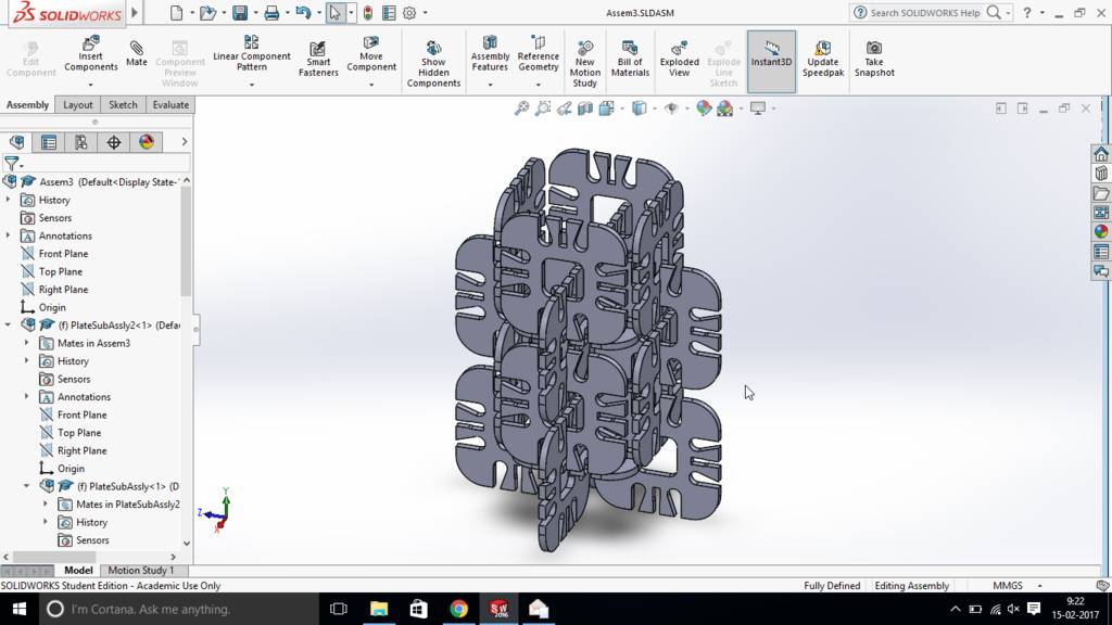
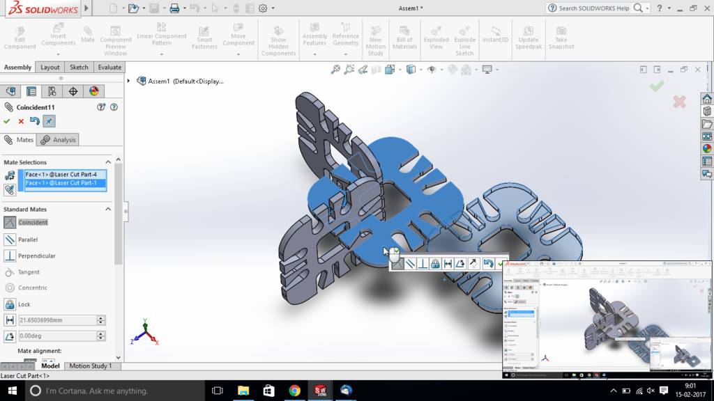
In assembly mode. I had imported existing component for multiple times
After activating "mate" command from tool bar. I have selected surfaces to align in two different components and it shows an option to Coincident, Parallel or Perpendicular
Based on entity selected solidworks provide options to add constraints to align those two components. In case of conflicts it shows conflicts too.
Finally entire thing is assembled
Files for download
Creating Final project model using solidworks
Making outer box
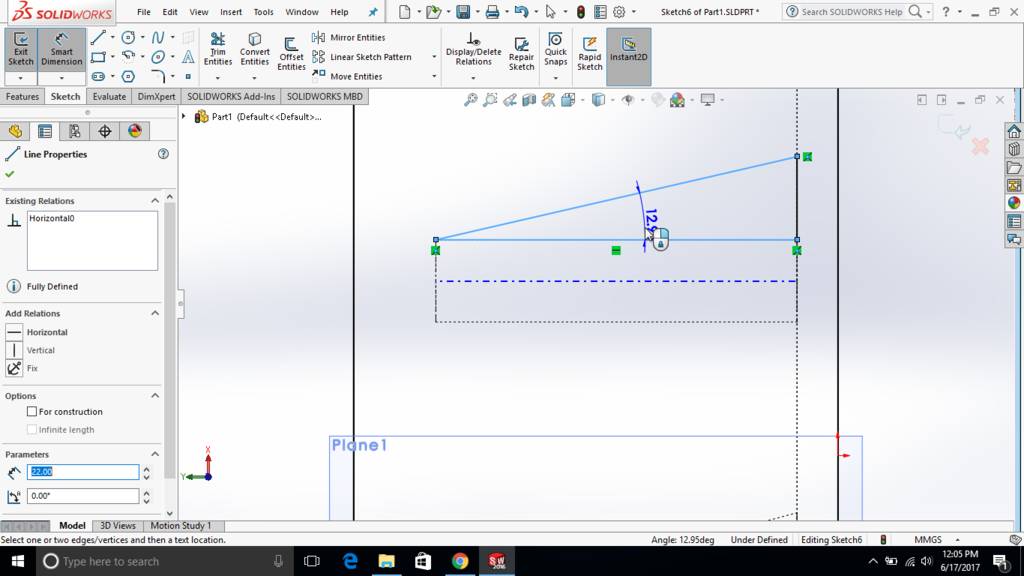
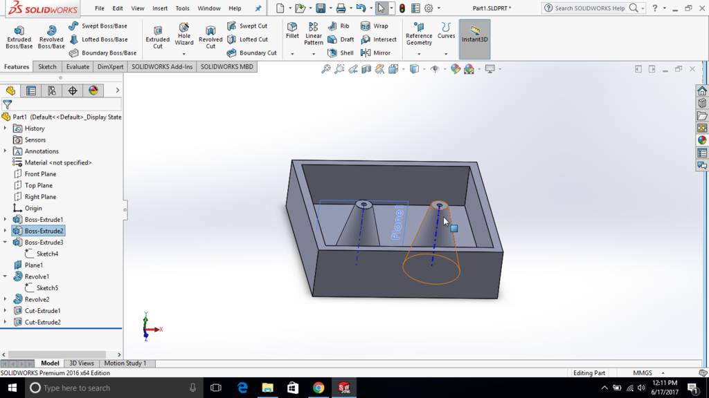
Creating a reference plane and support
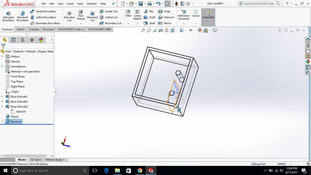
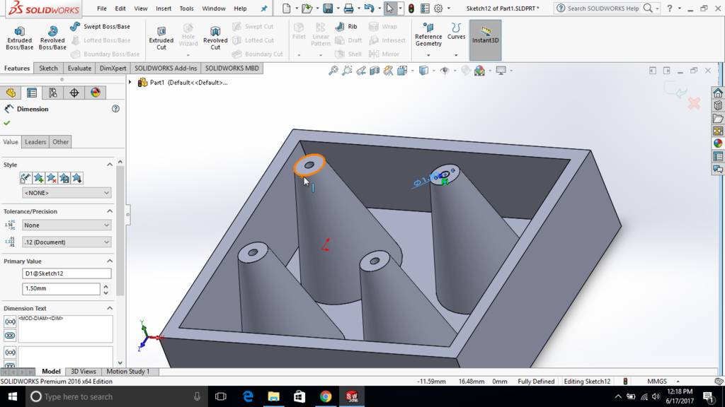
Revolve to form conical support
Sketch is created wit 15 deg angle for cone
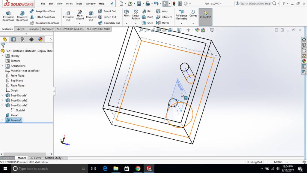
Created another sketch on same reference plane

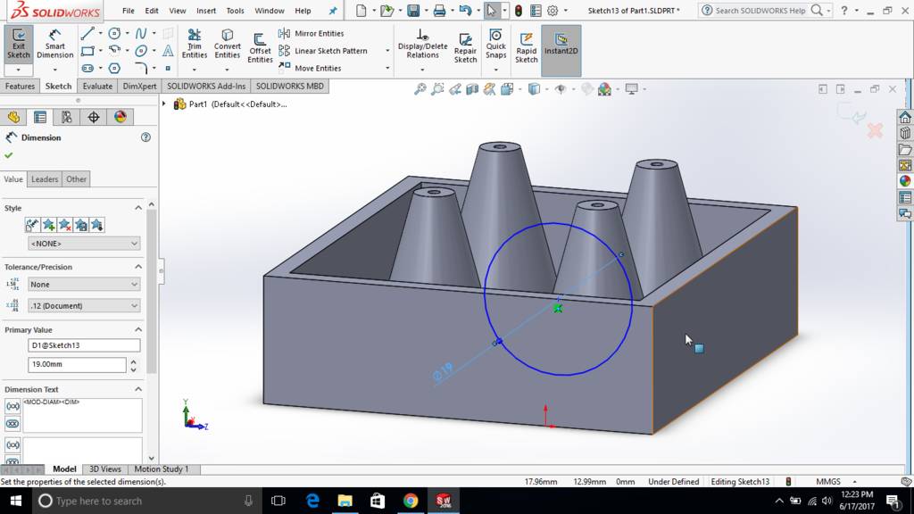
Second conical surface
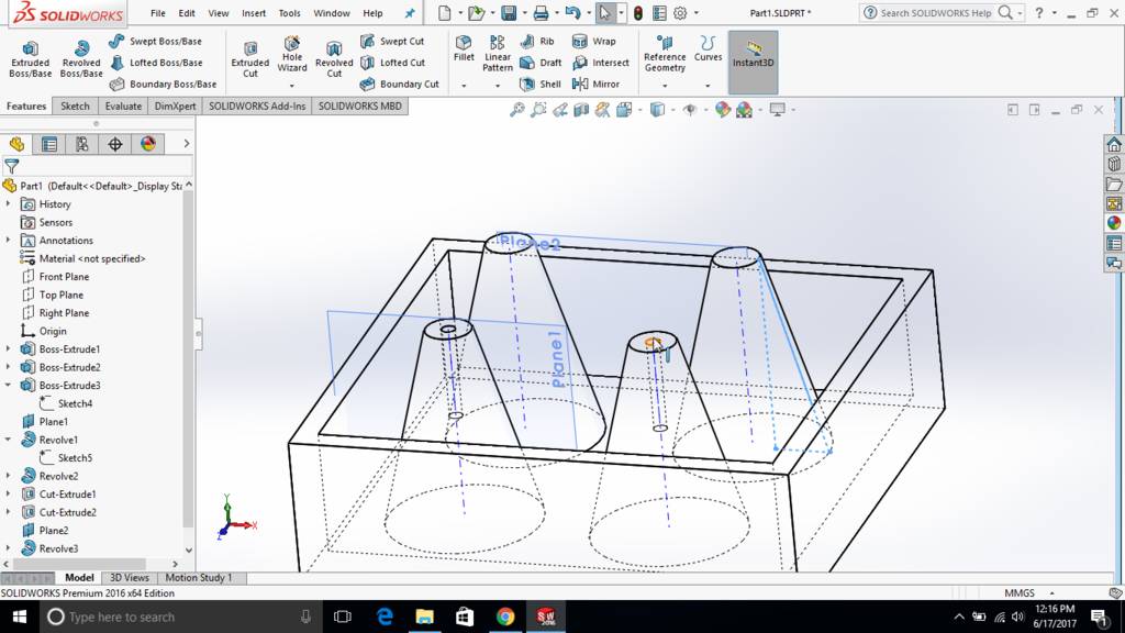
Created another two cylinders

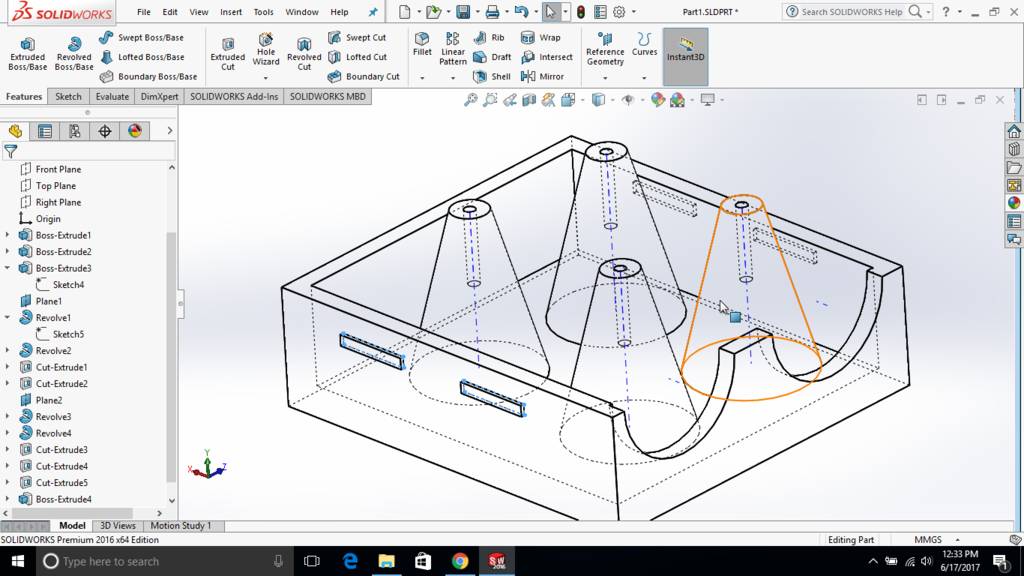
Revolve tool to create cone
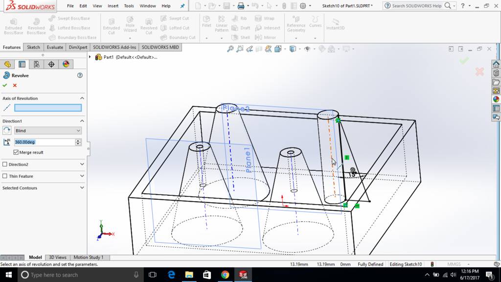
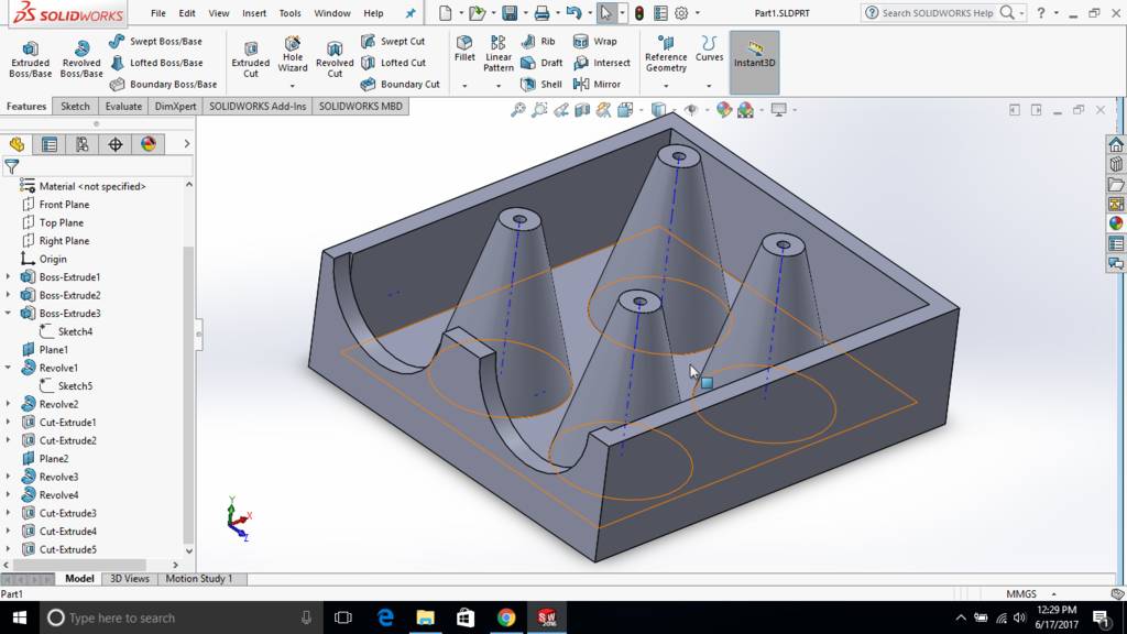
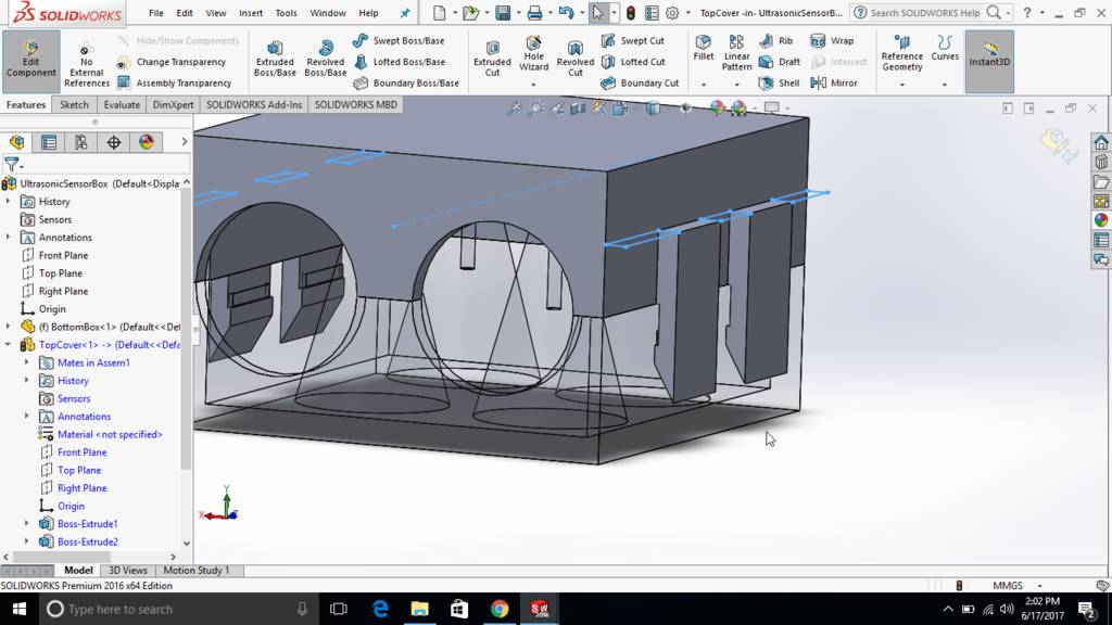
Used wireframe view to see interiers
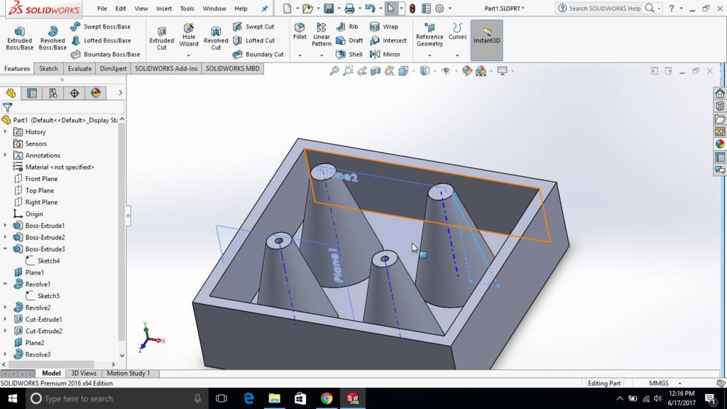
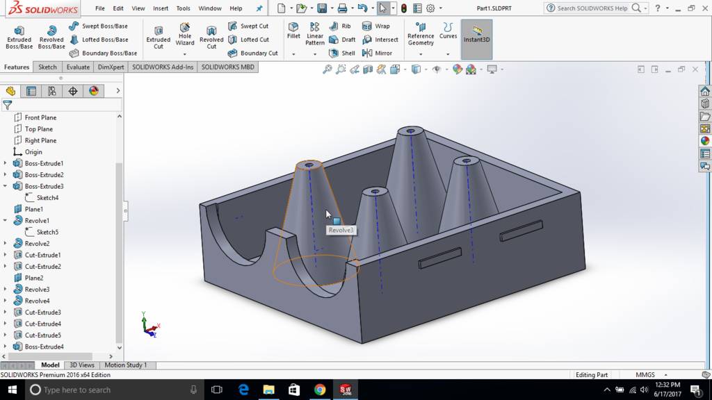
Used solid mode to see how its actually going to look
Drilled hole at the top of cone for clamping of board
Extrude cut to form opening
Create two of such holes
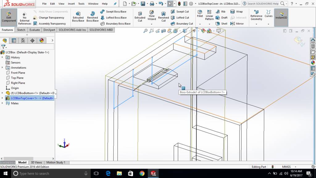
Created extruded notches at the side of a box for snap fitting purpose
This is how notches looks in wireframe mode
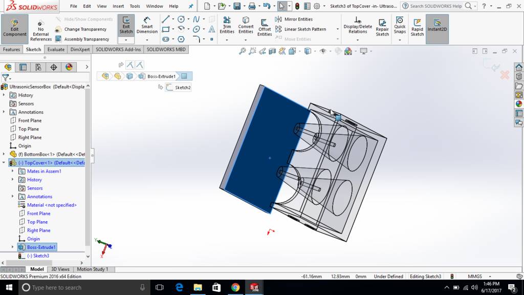
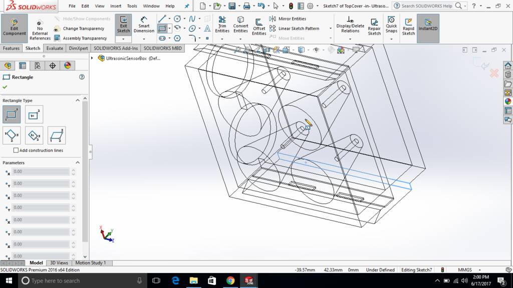
Creating top cap
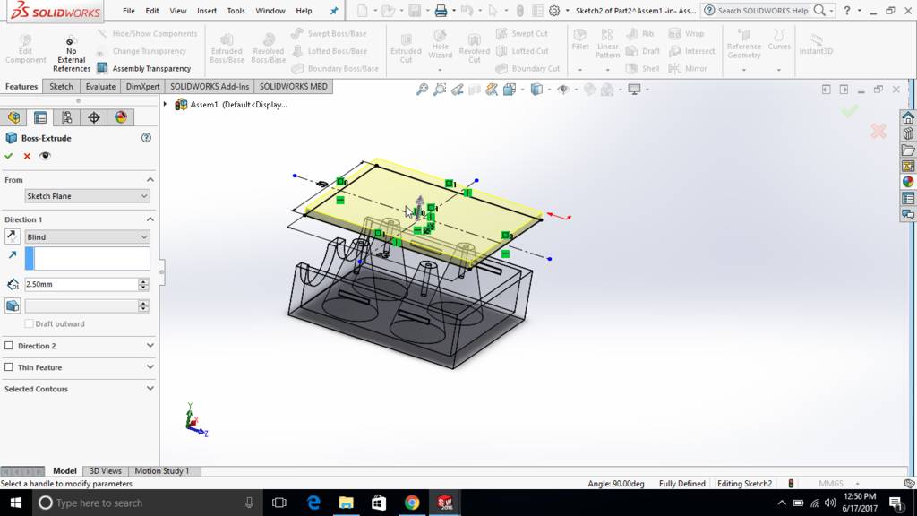
Skethc extrude to form a plate
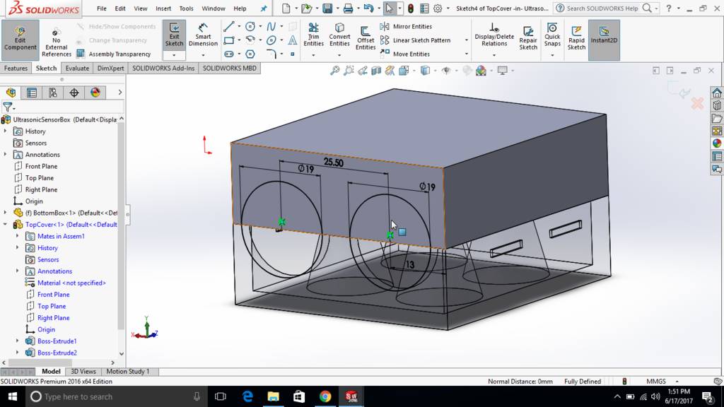
Another sketch extrude to form hollow box shape
Snap fit jaws are created and extruded
Extruded jaws are aligned with extruded notch to snap fit
Extrude cut from top surface to trim snap jaws
This is how jaws are lookign after extruded cut
Clamping lug is created

Extrude cut is used to reduce its thickness
Final ultrasonic slave module case is ready
Started master board casing
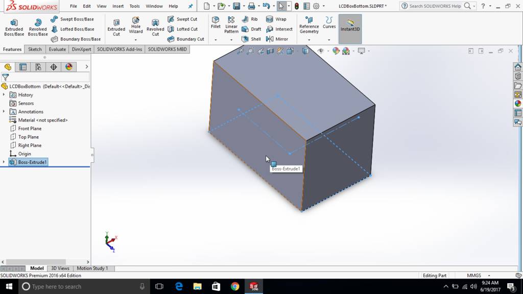
Used a sketch and then extruded
Hollow section is extruded
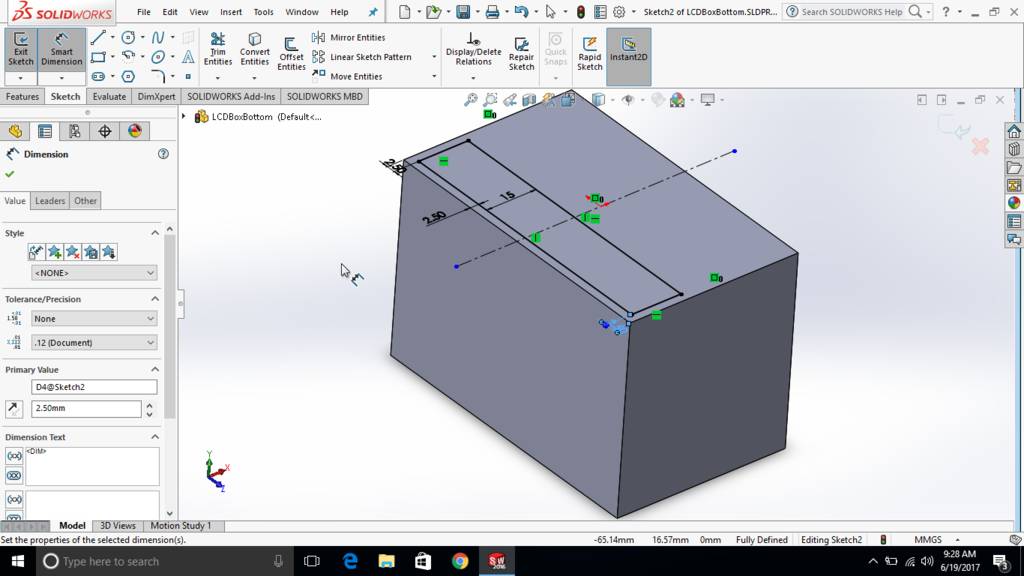
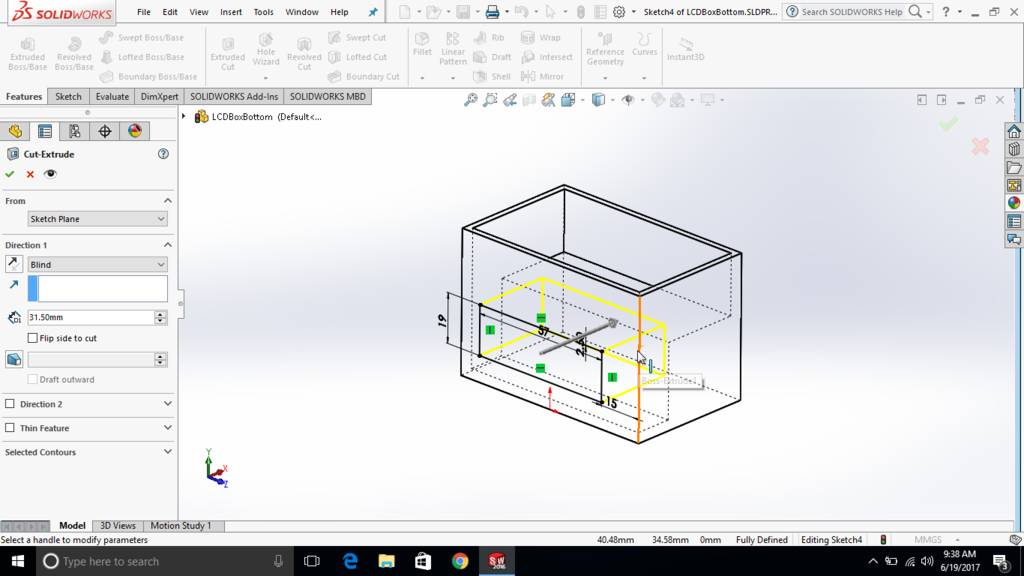
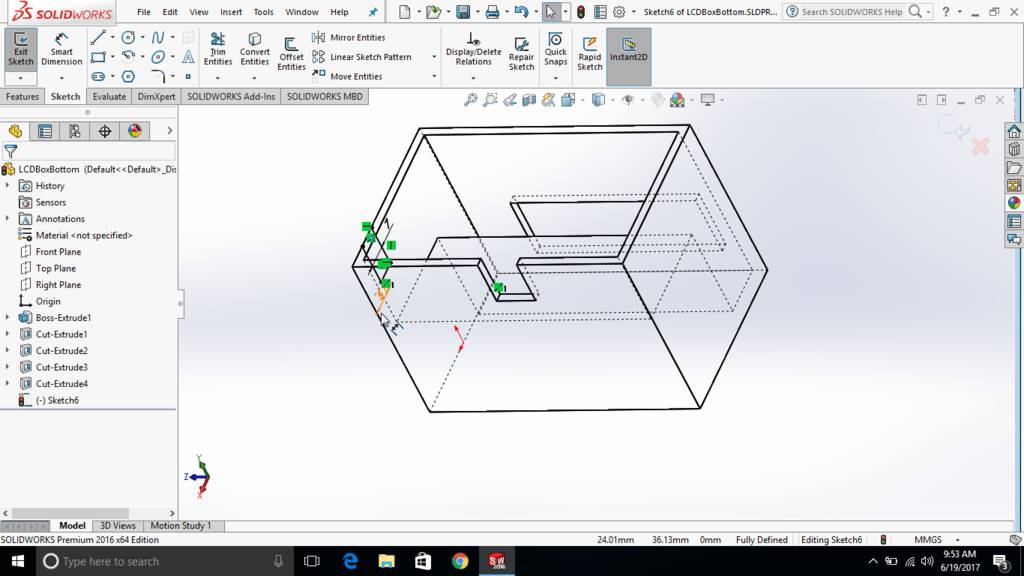
Sketch created at the sides to create opening for LCD

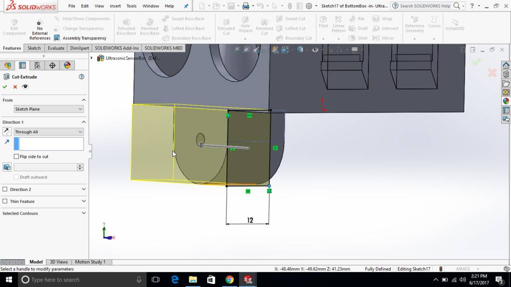
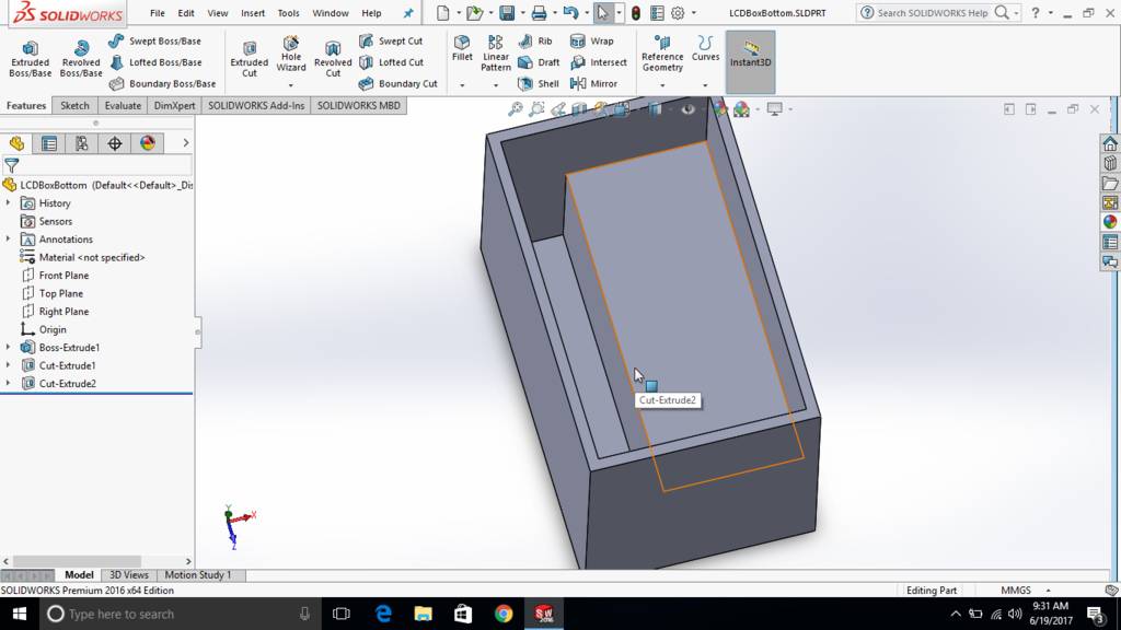
Sketch is then extrude cut to form an opening
This is how its looking in solid

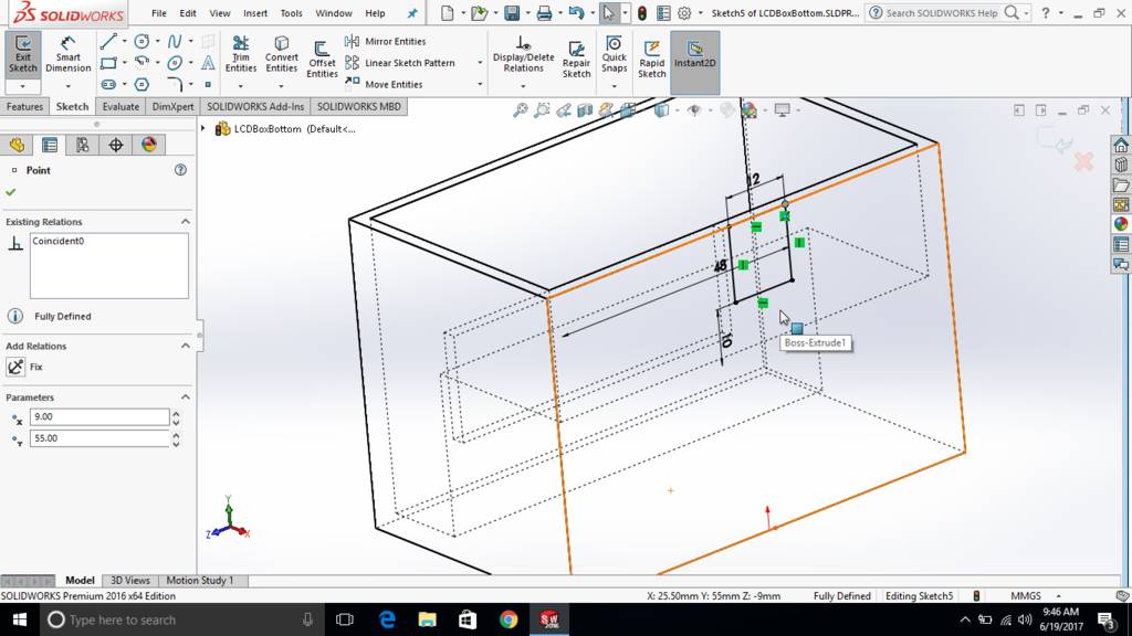
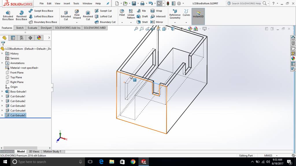
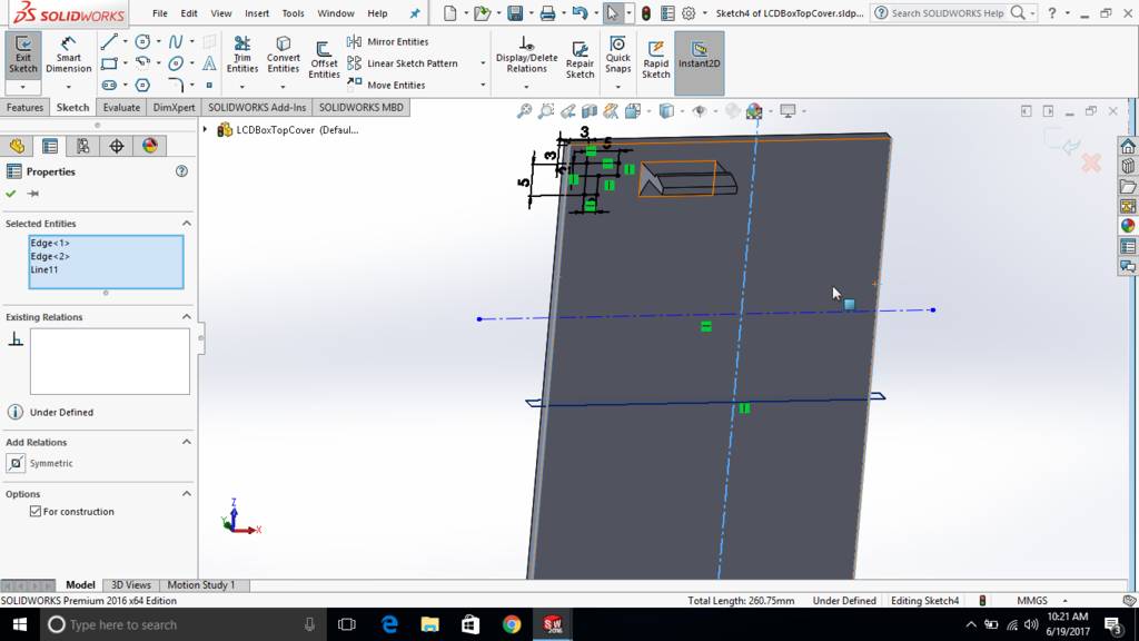
Sketch created at back wall
Use of distance tool
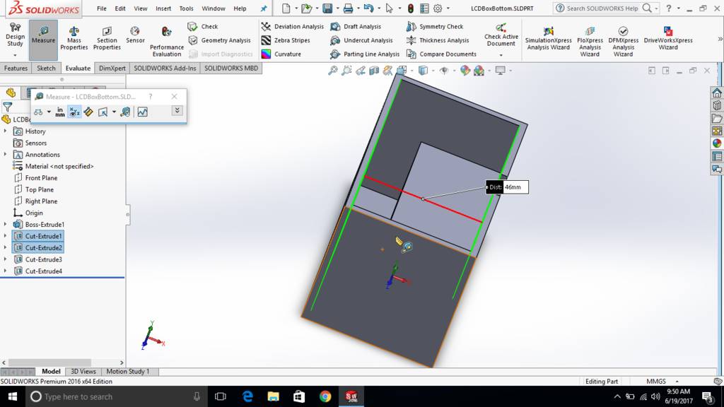
Second notch to insert another set of wires
Both the notches can be seen in screenshot
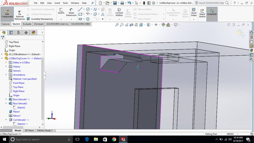
Created projected notches for making snap fitting
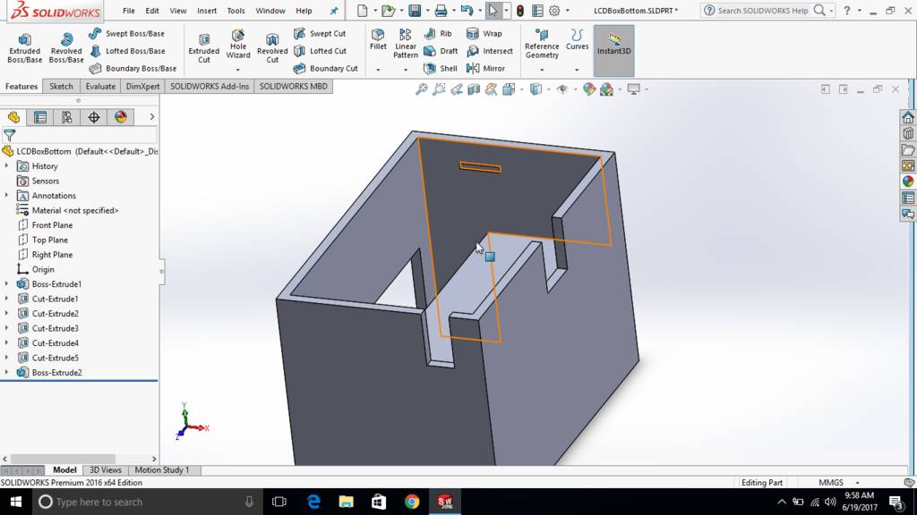
Created extruded jaws for snap fitting
Jaws are then trimmed using extrude cut feature
This is how it look like
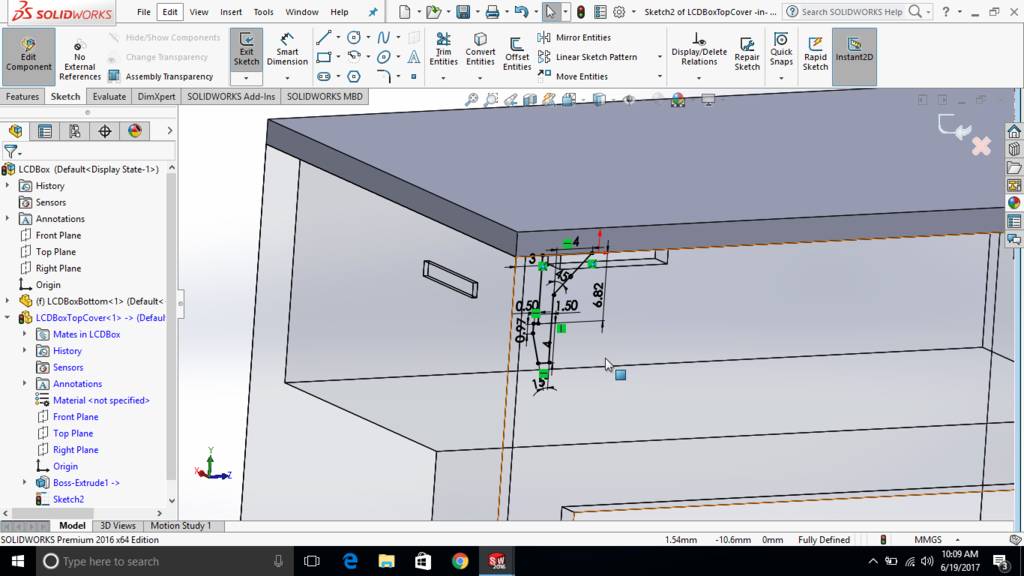
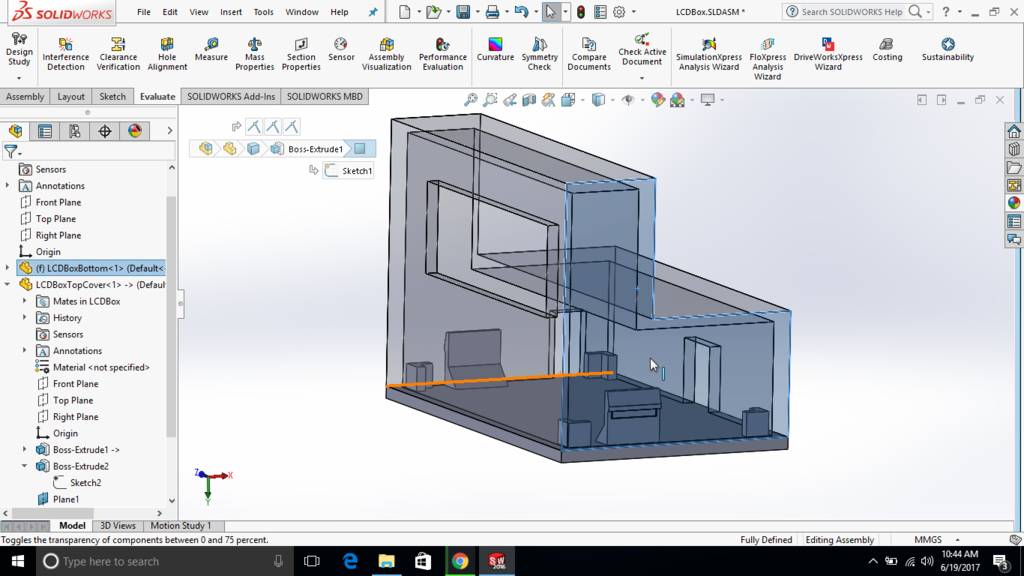
Created locators to prevent top plate from moving
This is how top plate is then mounted over master board box
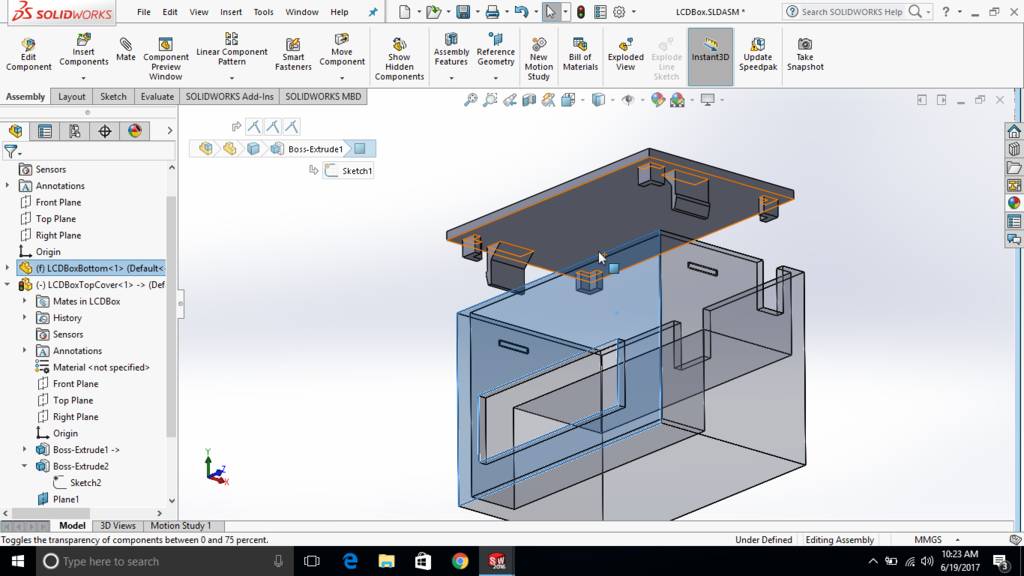
Inverted upside down. This is a final position of a box
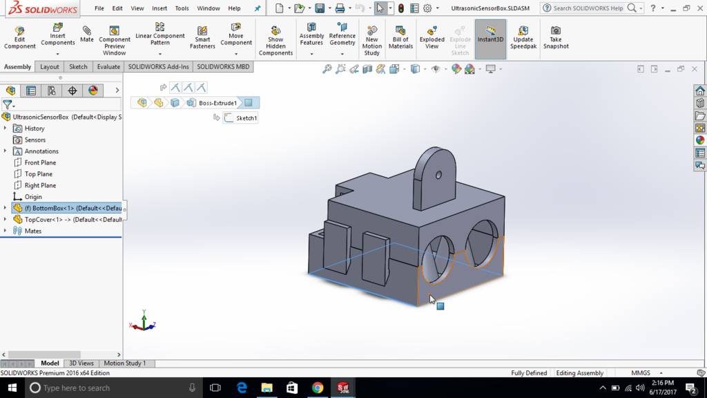
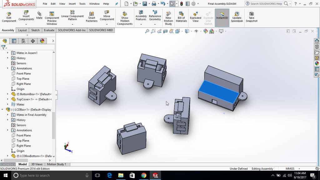
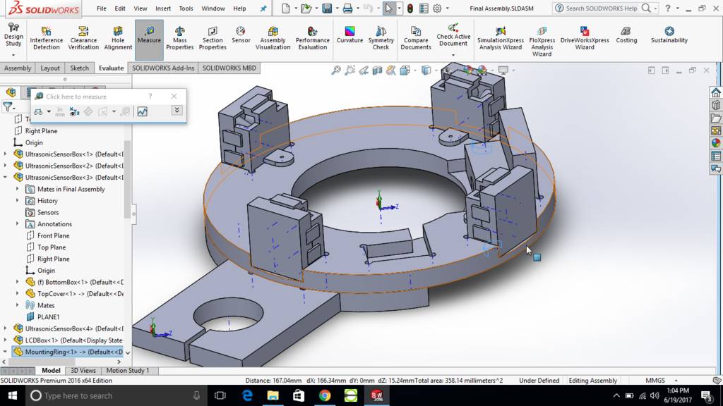
All components are taken in assembly mode
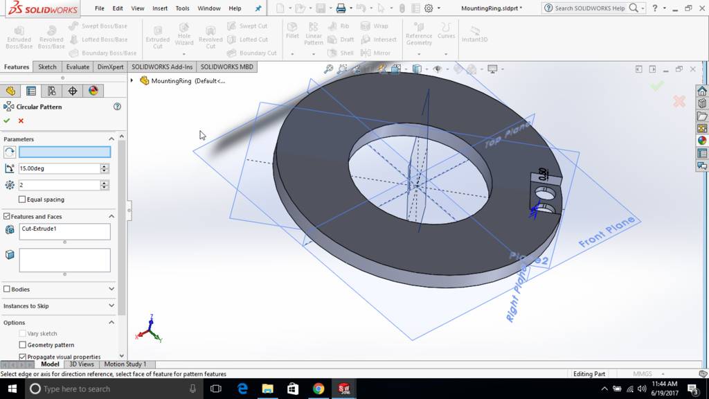
Mounting ring is then created in assembly mode
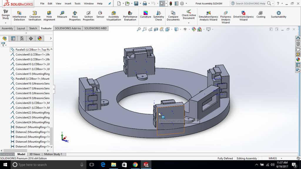
Cavity is created in mounting ring
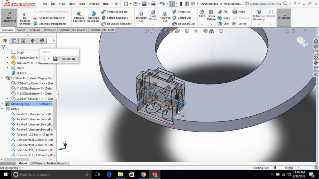
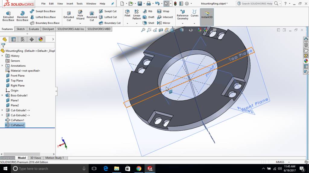
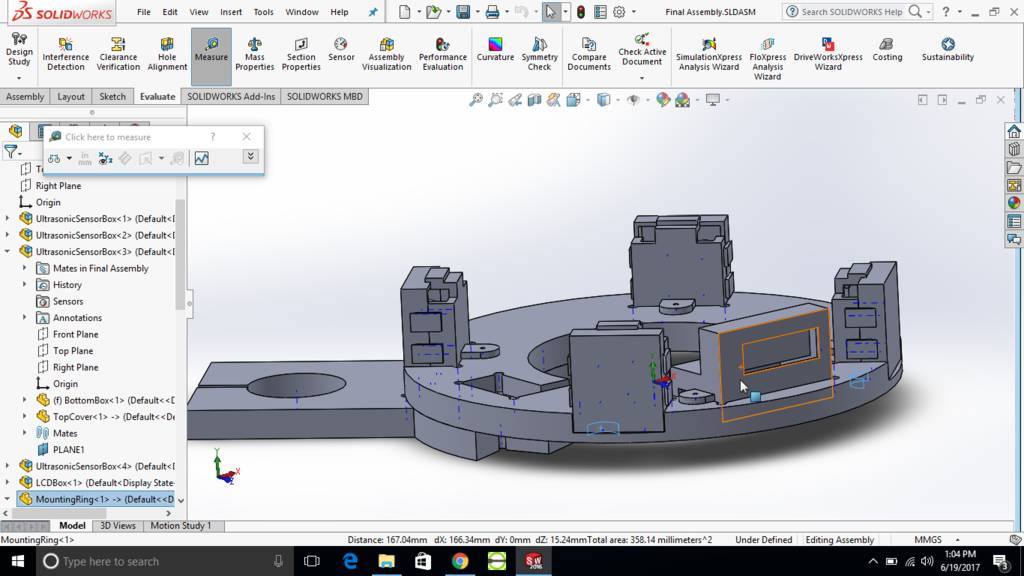
Mounting ring is then edited separately
Pockets are then mirrored and total 4 pockets are created
Master board is also placed at location
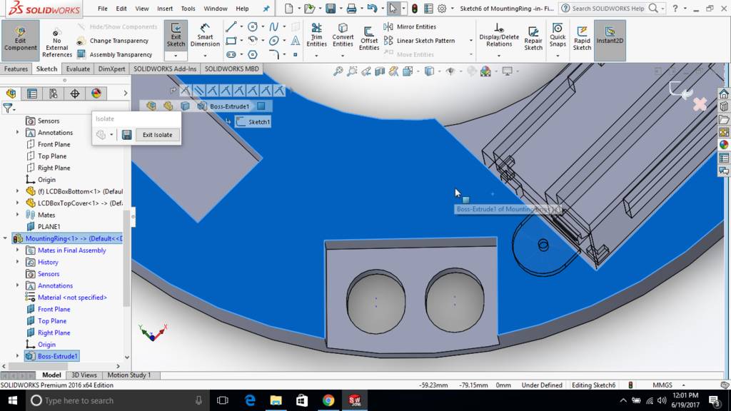
This is how it looks in wireframe mode
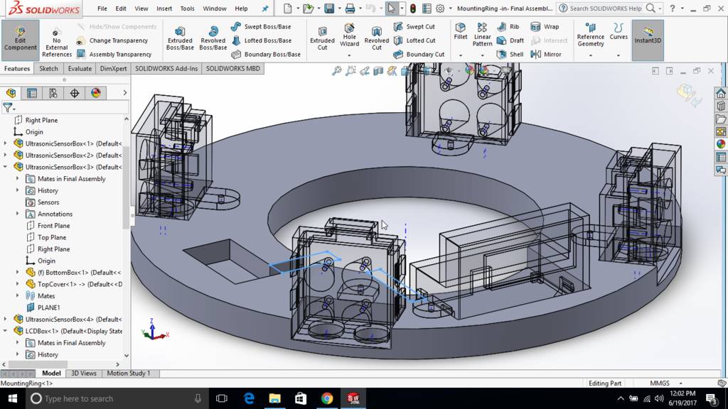
This is how it looks at final
LCD opening is at the front
Files for download
| 3D Design Files made using Solidworks | DesignsSolidworks.zip |
Exploring Blender to make model for moulding and casting assignment
Use Numpad 7 Key for top view
Press numpad 5 to be in ortho mode.
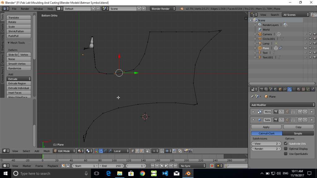
Insert line and press Tab to enter in edit mode.
Press ctrl tab and select vertex select mode.
Select vertex and press E to extrude.
Make a shape as required. as shown in screenshot
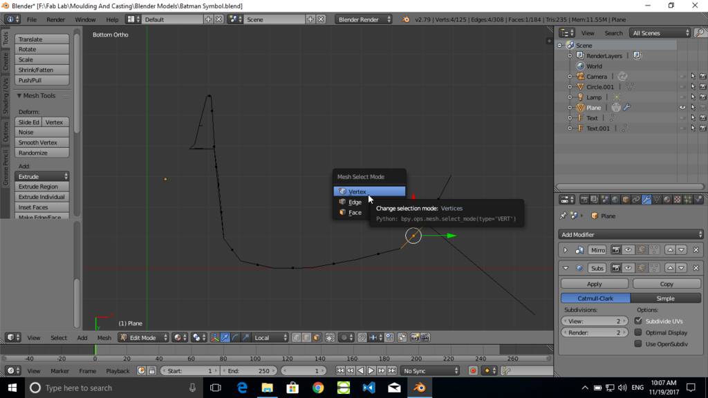
Extrude vertex to form a required Shape
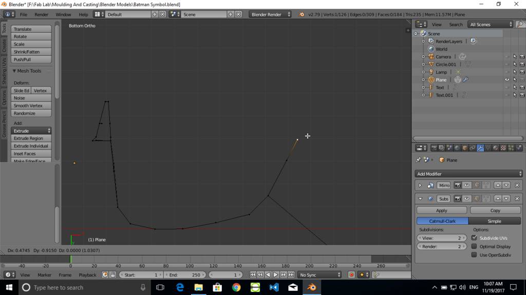
Draw complete outline as required
Add another line geometry
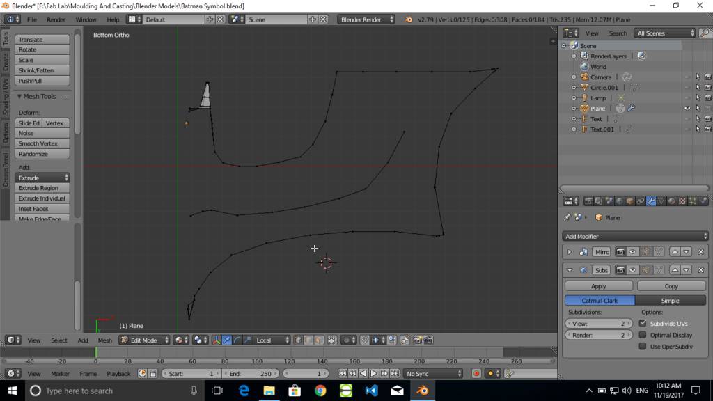
Join two points
Created line joining two vertrice points
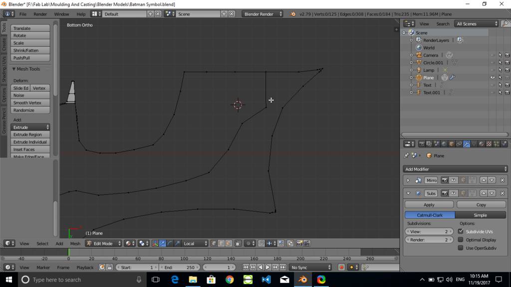
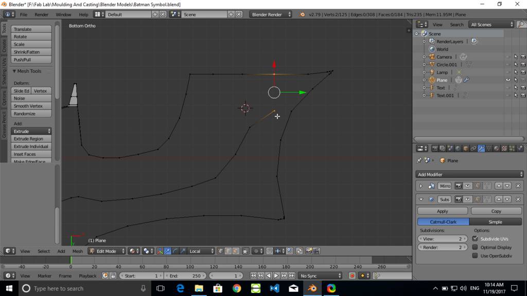
Create faces
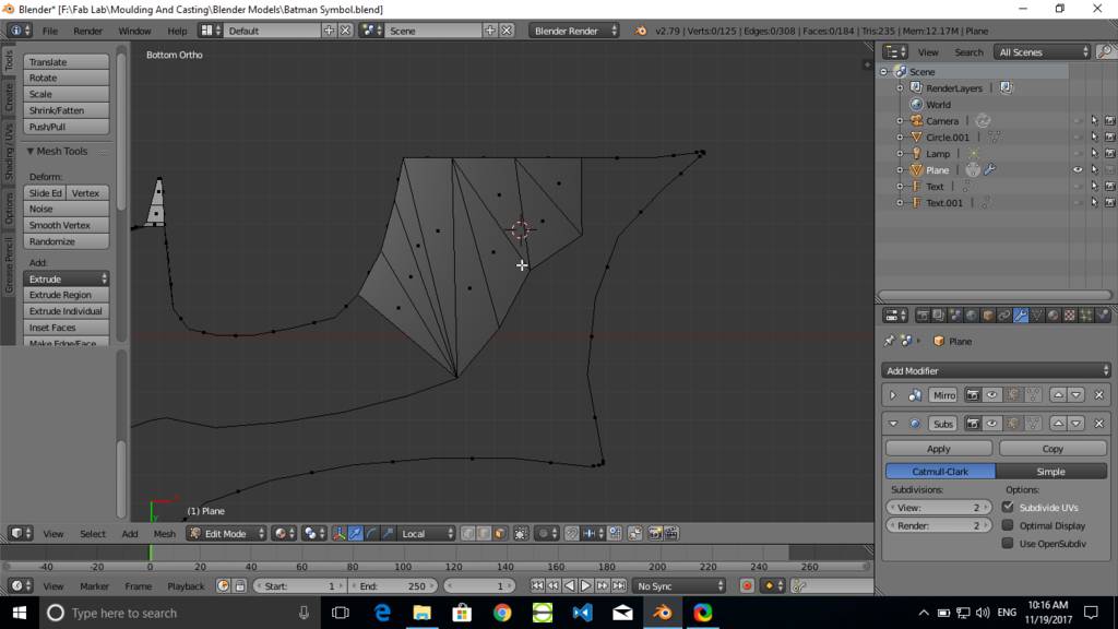
Create remainaing faces to form a geometry
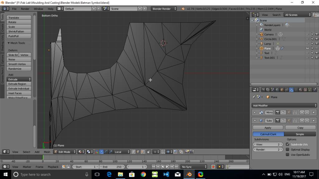
Create thickess to model
Manually move edges up to form required thickness and geometry
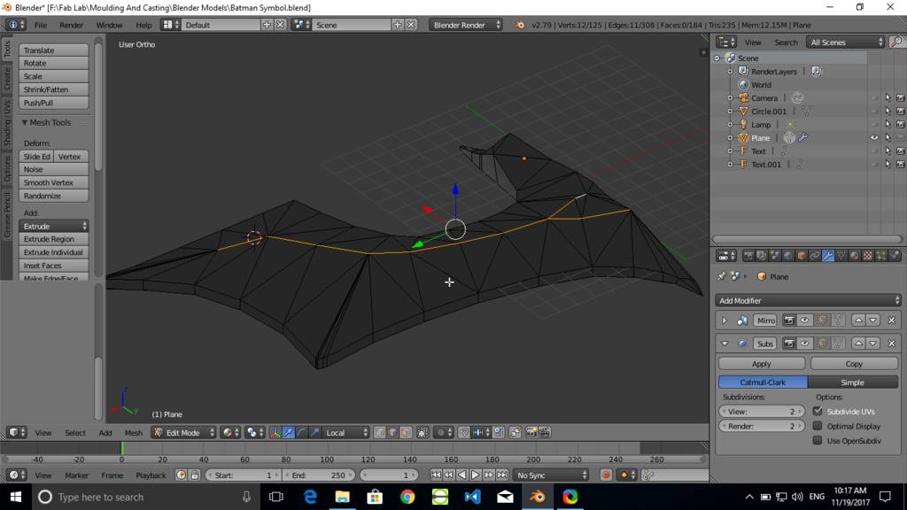
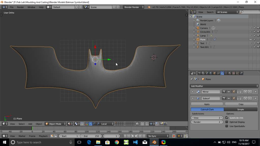
Use modifiers
- Add mirror modifier to create mirrored geometry
- Add subsurf modifier to create smooth surface of geometry
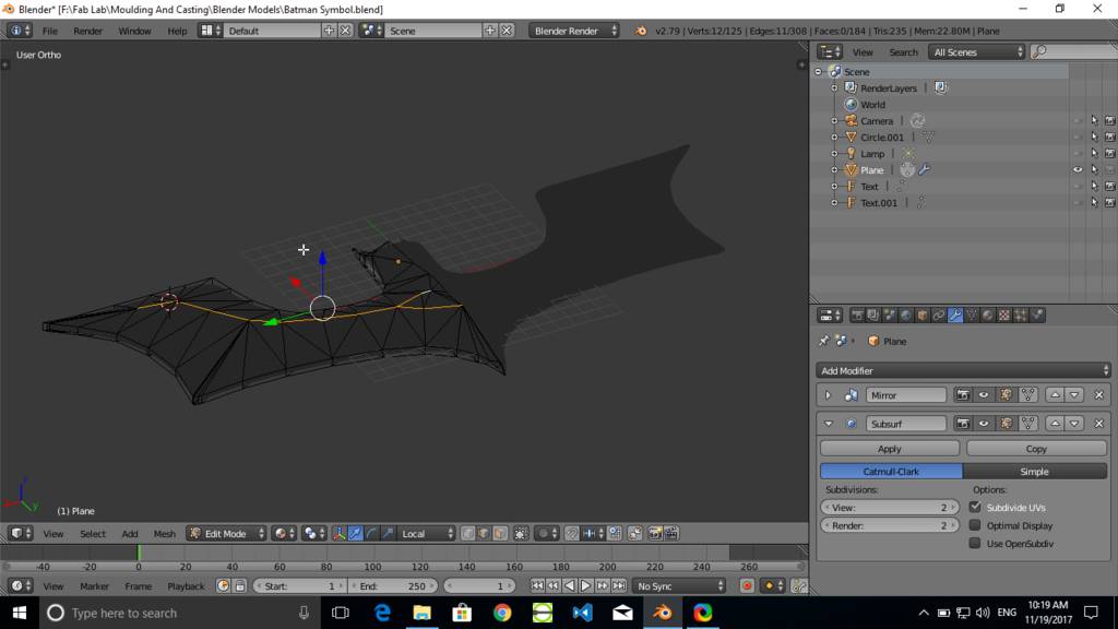
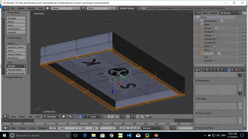
Basic completed model for batman symbol
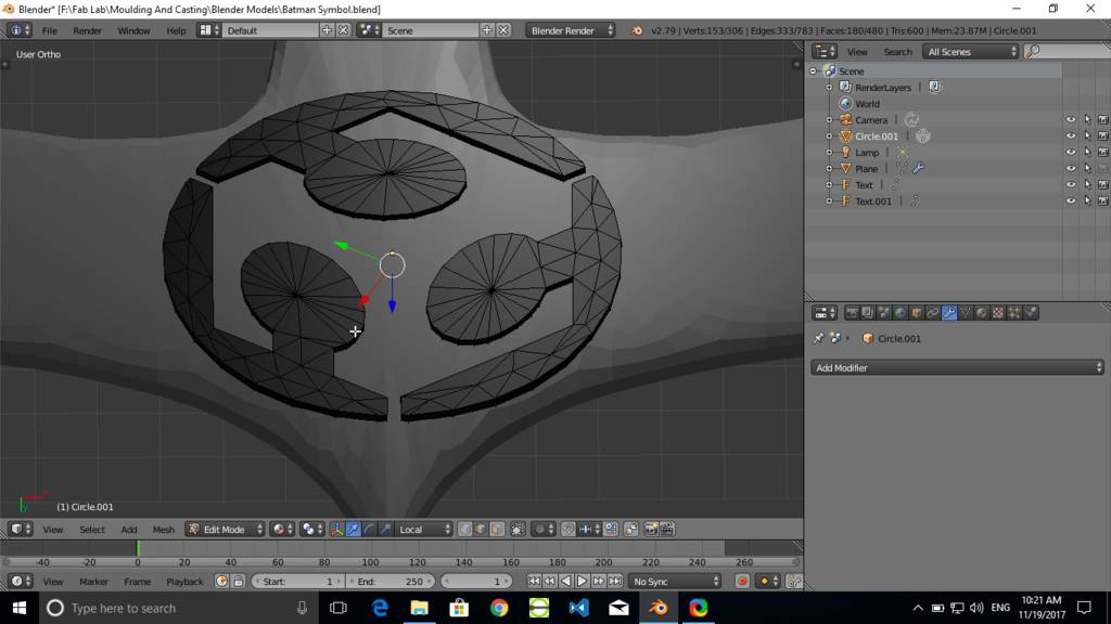
Created fabacademy sumbol
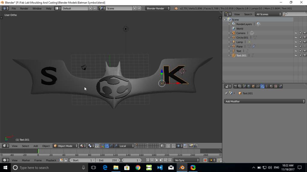
Creating letters
Crerated parting plane
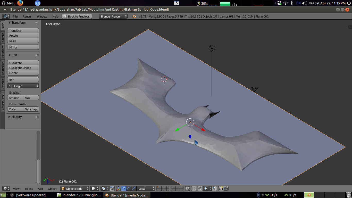
Form a rectangular mould cavity
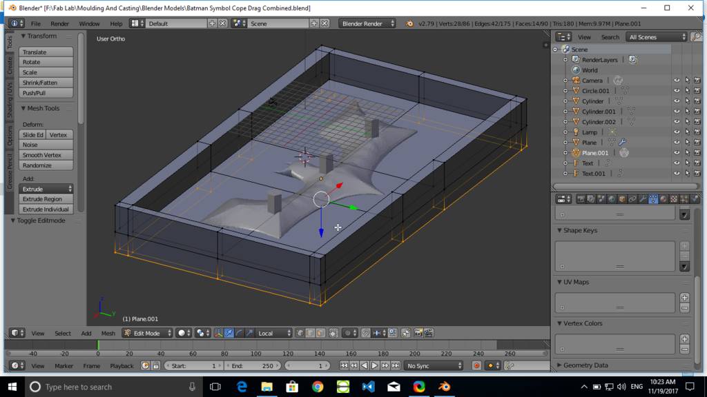
At the bottom it looks like this