Input devices
Week assignment:
· Measure something. Add a sensor to a microcontroller board that you have designed and read it
Input devices usually translate physical interactions into digital data, and that's what makes them so interesting and specially when it comes to learn how they work. In this assignment I used a ultrasonic range module, to measure distance. The PCB is based on Neil's work.
This is the whole list of components needed:
· 1uFapacitor · 10K resistor · 2x3 pin header · FTDI header · Attiny45 · Ultrasonic-HC-SRO4
I downloaded the library for the ultrasonic sensor here and then insert all the components into Eagle's.
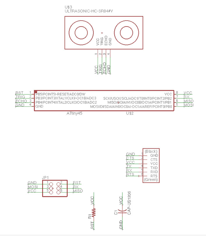
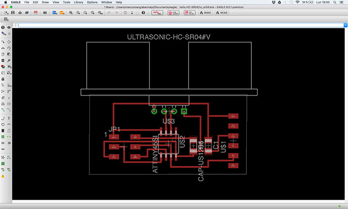
This is the final Eagle's schematic of the board, once the components were placed and connections among them were done. All of them were based in Neil's board but made some changes to fit everything and don't have any issues with the traces.
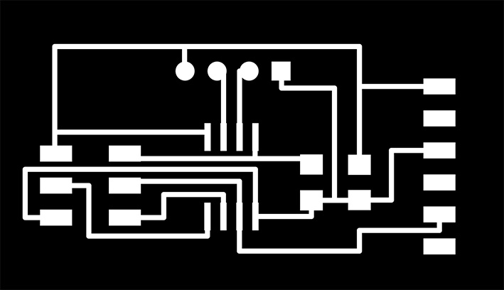
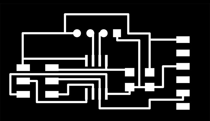
Traces of the board, once the eps was generated and was converted into a png file.
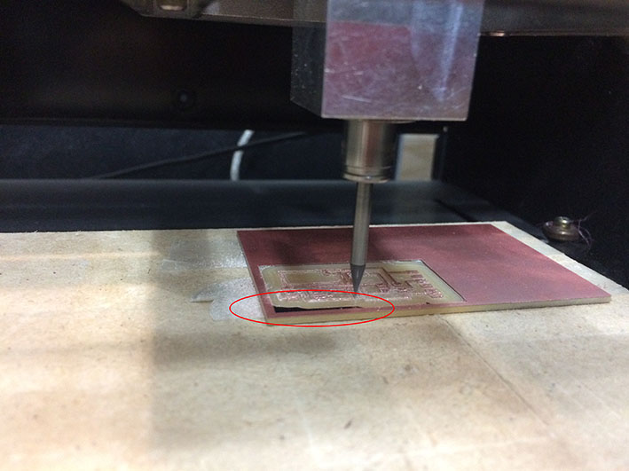
I milled the board with the MDX-20, as I have been doing over the last weeks. This time I had a small issue, as the wood surface wasn't completely flat, and the mill didn't remove all the copper from the board at once. Anyway, I milled it twice and the problem was solved.
I soldered all the components, except the ultrasonic sensor, as we didn't have it in the lab, and I had to buy it a few days after. However I programmed it without the sensor, to see if that was even possible (and was)
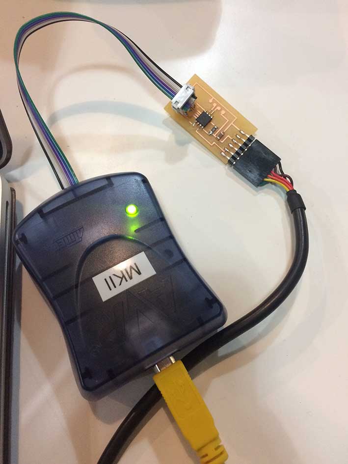
As I did in the outputs assignment, I first set the fuses to 8Mhz with Arduino and then download the C code from here and the make file from here and then used the AVRISP MKII to upload the code into the board.
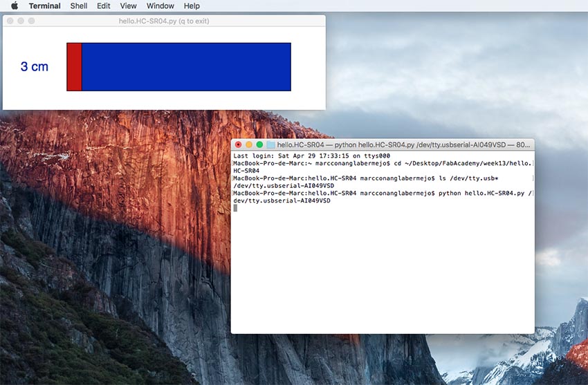
To read all the data from the sensor through serial we need first to know the name of the port. To do so we write the following line in terminal: ls /dev/tty/usb*
Once the name of the port appeared, we could use it to upload the python file to it.
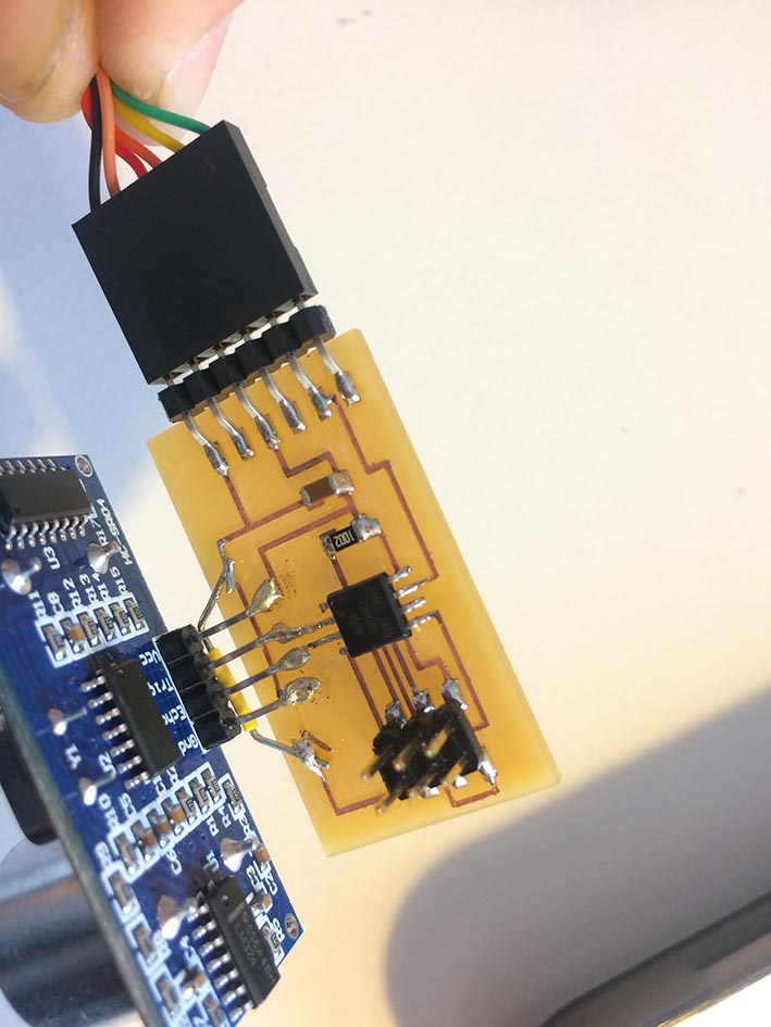
Once I had everything ready I soldered the sensor to the board, and worked fine for a while. Afterwards I realized the sensor itself was touching the trace above, as it was really close. I could see this was interfiring a bit on the reads, or at least is seemed that to me. I tried to pull a bit the sensor but unfortunately I broke the copper trace. I fixed it (a bit rude) with a jumper, and still worked fine.
Here's a video to see the sensor "live" whilst measuring distance to a white box.
pass: fab
Apart from that I try to use and read with Arduino serial port the data from the board, creating a new code for this IDE. To understand how the pins work I read at this datasheet:
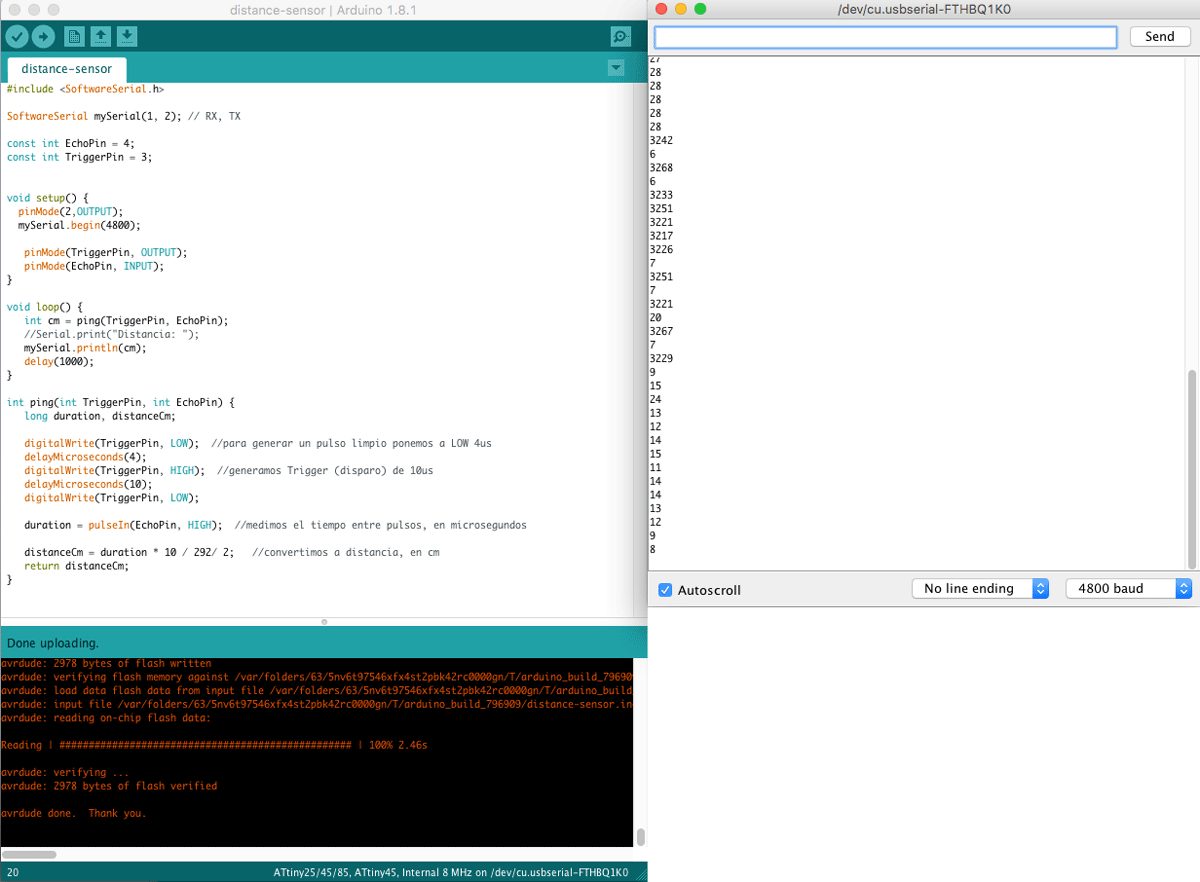
#include SoftwareSerial.h

SoftwareSerial mySerial(1, 2); // RX, TX

const int EchoPin = 4;
const int TriggerPin = 3;


void setup() {
  pinMode(2,OUTPUT);
  mySerial.begin(4800);

   pinMode(TriggerPin, OUTPUT);
   pinMode(EchoPin, INPUT);
}

void loop() {
   int cm = ping(TriggerPin, EchoPin);
   mySerial.println(cm);
   delay(500);
}

int ping(int TriggerPin, int EchoPin) {
   long duration, distanceCm;

   digitalWrite(TriggerPin, LOW);
   delayMicroseconds(4);
   digitalWrite(TriggerPin, HIGH);
   delayMicroseconds(10);
   digitalWrite(TriggerPin, LOW);

   duration = pulseIn(EchoPin, HIGH);

   distanceCm = duration * 10 / 292/ 2;
   return distanceCm;
}
Download all the files here