We had the Neil Gershenfeld's on 1st March, on the electronic circuit PCB designing and programming. This was officially my first week to get a lecture on electronics, and got to know about many softwares where I can design the PCB.
This week's task was quiite interesting, as "Neil Gershenfeld" said, this is the most interesting and quite busy week. We had to learn multiple tools as well as multiple softwares to complete this week's assignment.
For this week we were given task to make something out of the plywood material, the first and the most important thing was to get an idea of what I am going to make out of wood.
For that I always had something in my mind, I wanted to make a stand where we can hang our jackets and bags, as we didn't had such a thing in here.
For the first part, I checked multiple diffrent clothes stands to get a general Idea what actually I want, and then started to make a general caluclations about it.

My idea about the thing which I wanted to make
For this model I first made a few sketches, and cut a model on the card board to check how it will look like after the product is ready
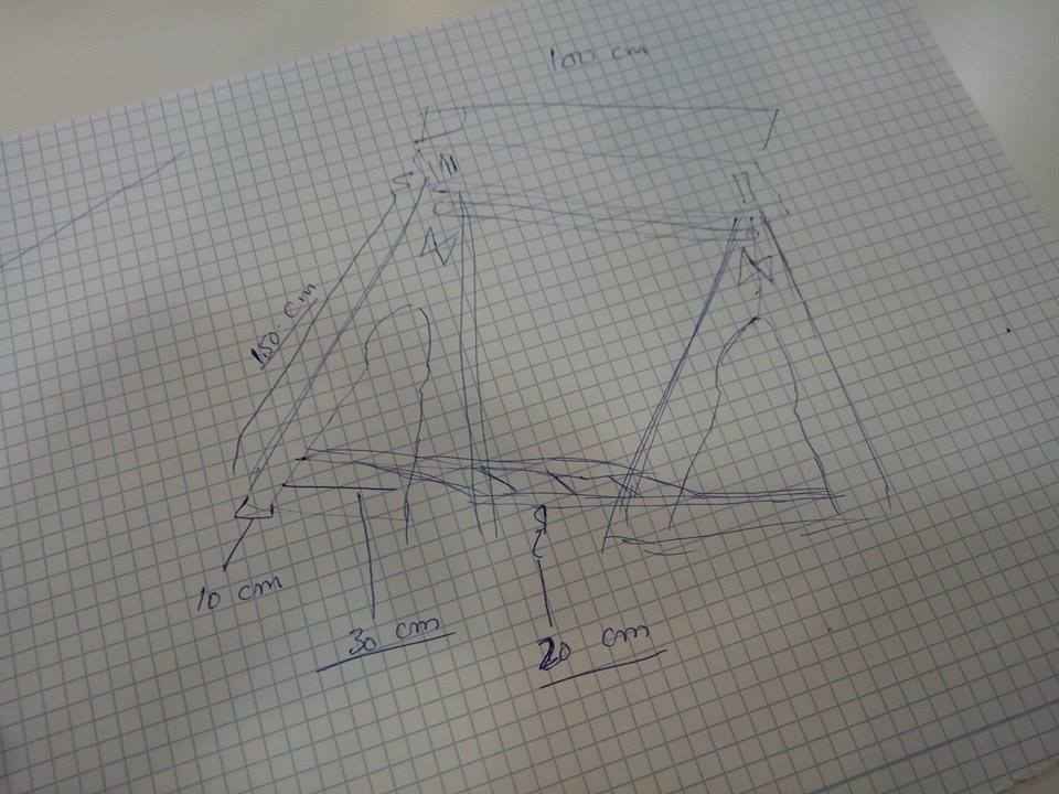
Paper sketch
Once paper sketch was done, now it was time for a few look and trials, about how does it will look after the model is ready, for that reason I cut my model from the "Card Board"
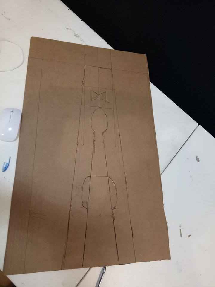
Card Board sketch
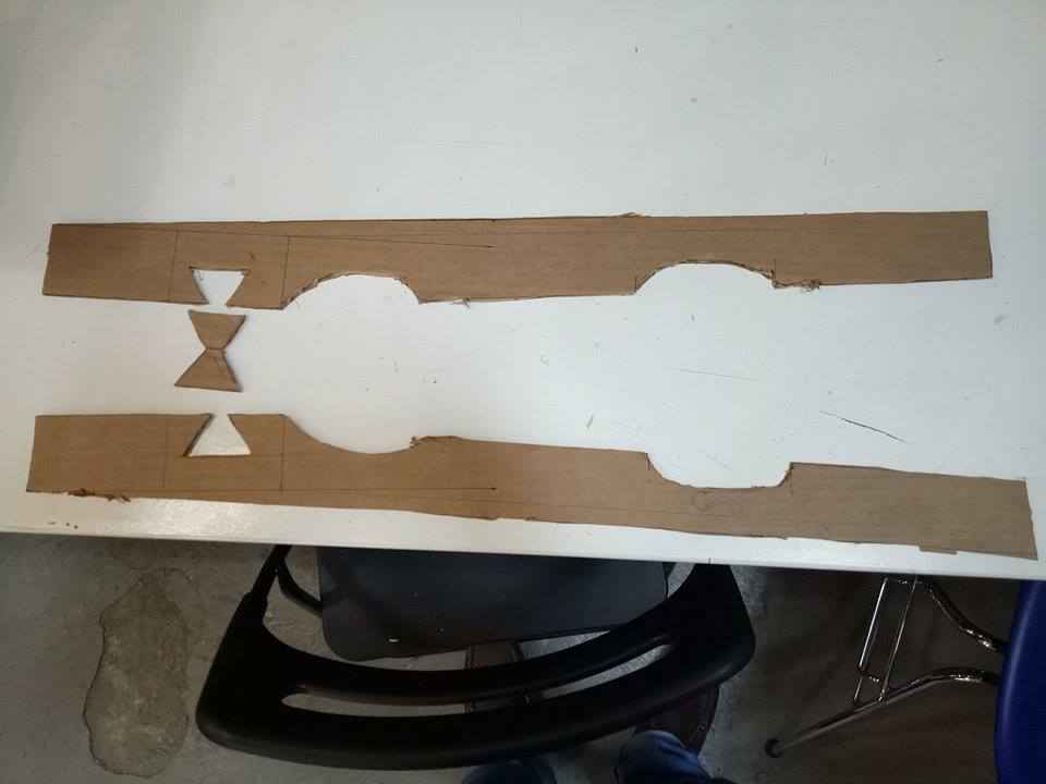
Card Board sketch Cut
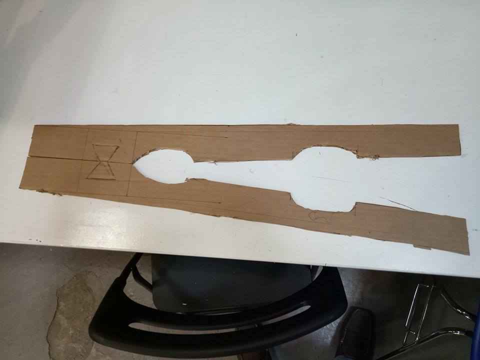
After joining the cut parts with joints
Well after getting a clear picture now it was time to get my model done on the CAD software, there are tons of softwares available to do that, but to learn one from scratch was a bigger challenge, So I went and started working on "Rhino" and "Solid works" after a few failures there, I left them both and started getting expereience on "AutoCAD Fusion 360", well it was a bit tricky as it works using cloud.
But it was a nice experience of getting a few failures, as this time I was quite faster and did what I wanted to do.
Here are a few fail attemps from fusion and a few examples which I made to get hands on practice
Fusion Failed and practiced attempts
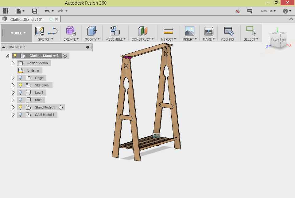
My Final Model with all the calculations
The only difficulty in getting this model was in creating paramatric design, all the inputs must be paramatric as the model can be changed based on if the data is changed, and the other challenge was the joints, that was really tough, I had to learn all the possible joints which I can use and also if the joint can be possibly done here
The joints to learn before start working
The joints to learn before start working
The joints to learn before start working
At the end of all that, I also learned about "Dog Bones" which is must to be created to fully fix the joints.
Once the model was ready now it was the time to nest it and get it ready to mill, and this part was quite challenging as Fusion by default doesn't provide nesting environment, so we had to go beyond the capabilities of the fusion 360 and make a nest for the model
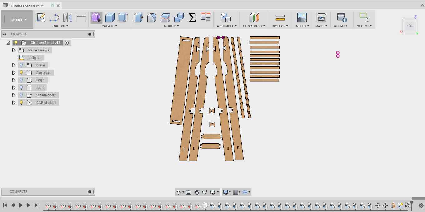
The nested model to be ready for G-Code generating
Now started the part which initially I thought would be so easy to do, it was to export this model to drawing ".dxf" format and make gcode using Rhino 360. But it happened to be quite difficult, as "Fusion 360" doesn't export whole model as ".dxf" format, it only exports a single component but I needed to export my model, which was conisisted of 38 components.
I tried various ways to do it, but not a single way was working for me, finally I exported my whole model as "Iges" and exported to "Rhino" instead of "Rhino CAM" and had to do nesting again.
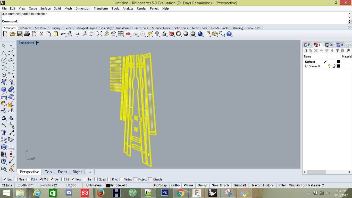
Imported IGEs Format to Rhino
When I imported my model into Rhino, instead of 2D Drawing, it was a 3D model, now I had to make it into 2D Drawing
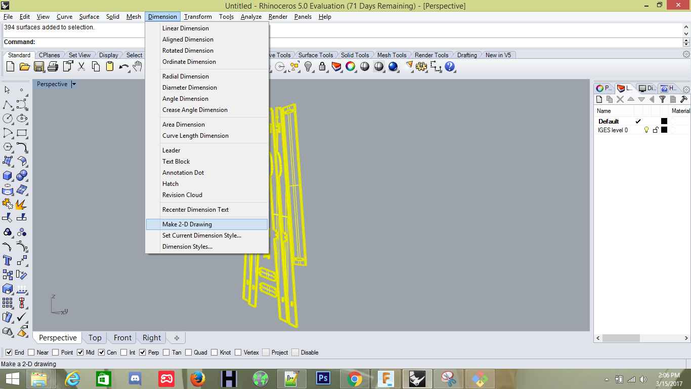
Making 2D from 3D part
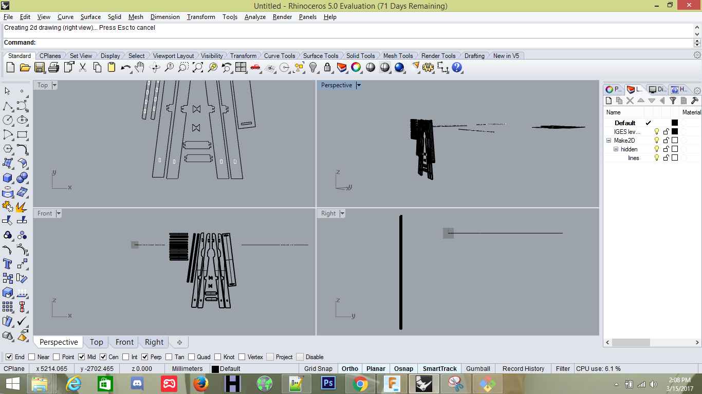
Result of "Make 2D", it removed the mesh and left only the inner and out meshes
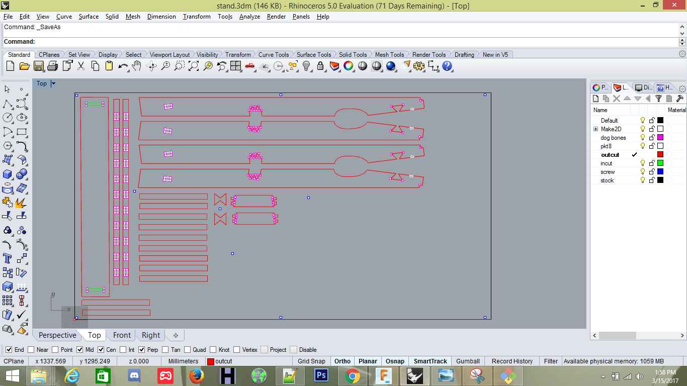
Now it was the time to create the Layers for the model (Screw, DogBones, Pocket, OuterCut, Innertcut etc), different layers for different reasons
The first thing to do in Rhino Cam is to create the stock, for this we were given 2450mm x 1250mm wood stock so I created the same size of Box Stock with 15mm depth.
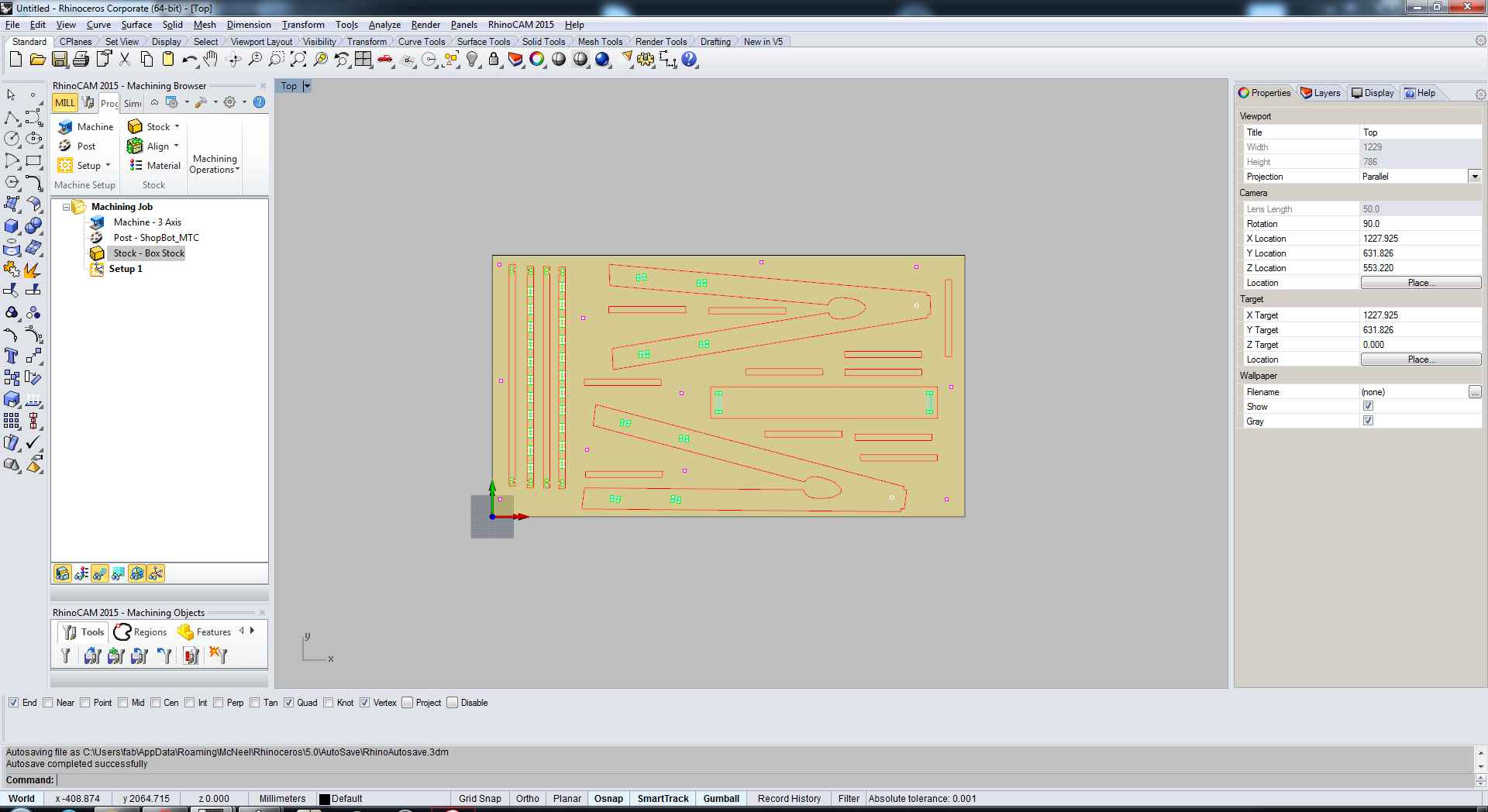
Created the stock
The second step was to create the Milling scheme for the screws, I selected all the screws and went in 2D milling to create a scheme for it and set the cut parameters and others.
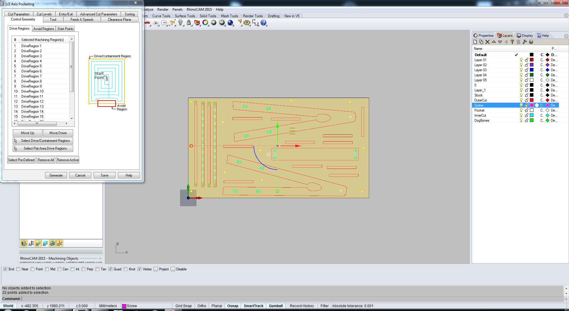
Creating screws scheme
The first thing in the cut parameters is to select the tool which we are going to use in the milling process, for my project I required 6mm Ball tool so I selected that one..
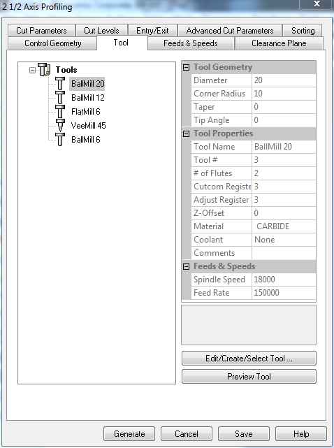
Selecting Tool
The next thing was to select the path, what path I want to mill my board in, whether the inner cut, or outer cut, how much offset etc.
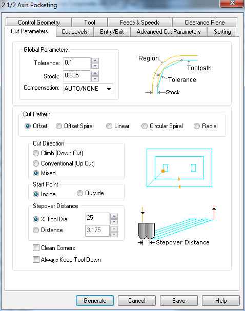
Setting cut parameters
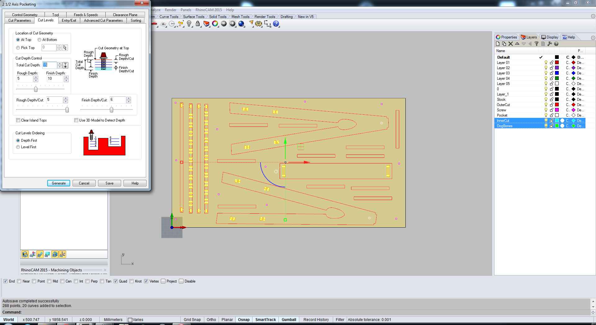
The next thing was to select the cut levels, this was the most important part because this part differentiates between whether I will cut through or will leave any part. Just like pockets or outlines. Here we have to define cut depth, how much deeper we want to cut.
Seemingly, for my screws scheme, I didn't wanted to go through whole stock so I selected half the size of stock so that I can screw it later using the tool manually.
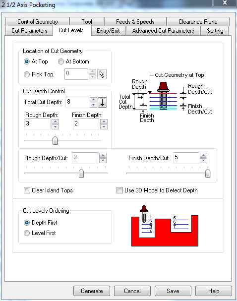
Setting cut levels
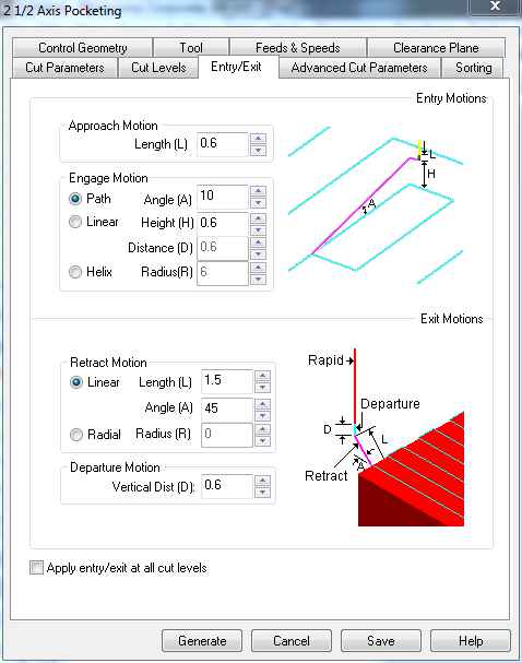
This shows the entry and exit point of the tool
Next come the speed part, where I defined the speed of the extruder. Normally we mill at around 12000-14000 RPM so I selected 12000RPM and rest with 2000.
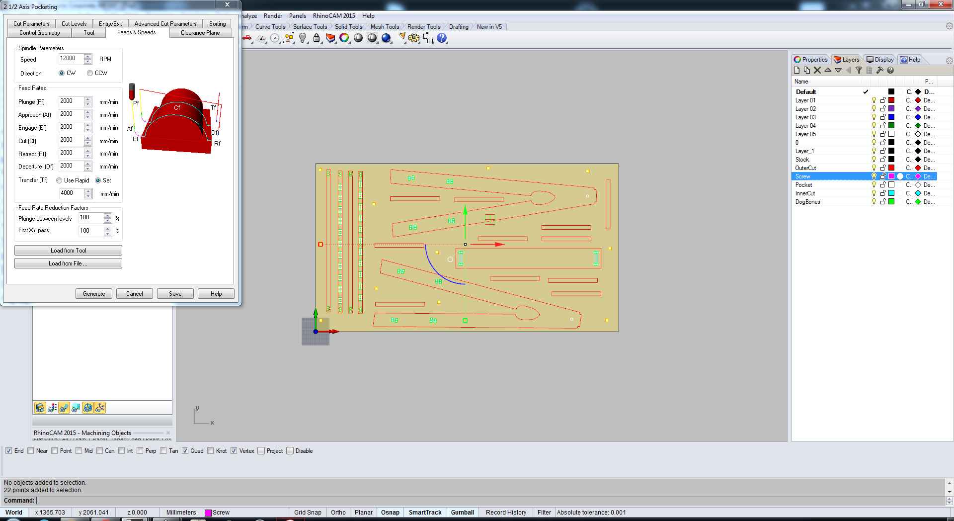
Feeds and Speed
And with this my Screws scheme was ready, next schemes were almost same just the cut depth and entry exit points were a little different.
Profiling
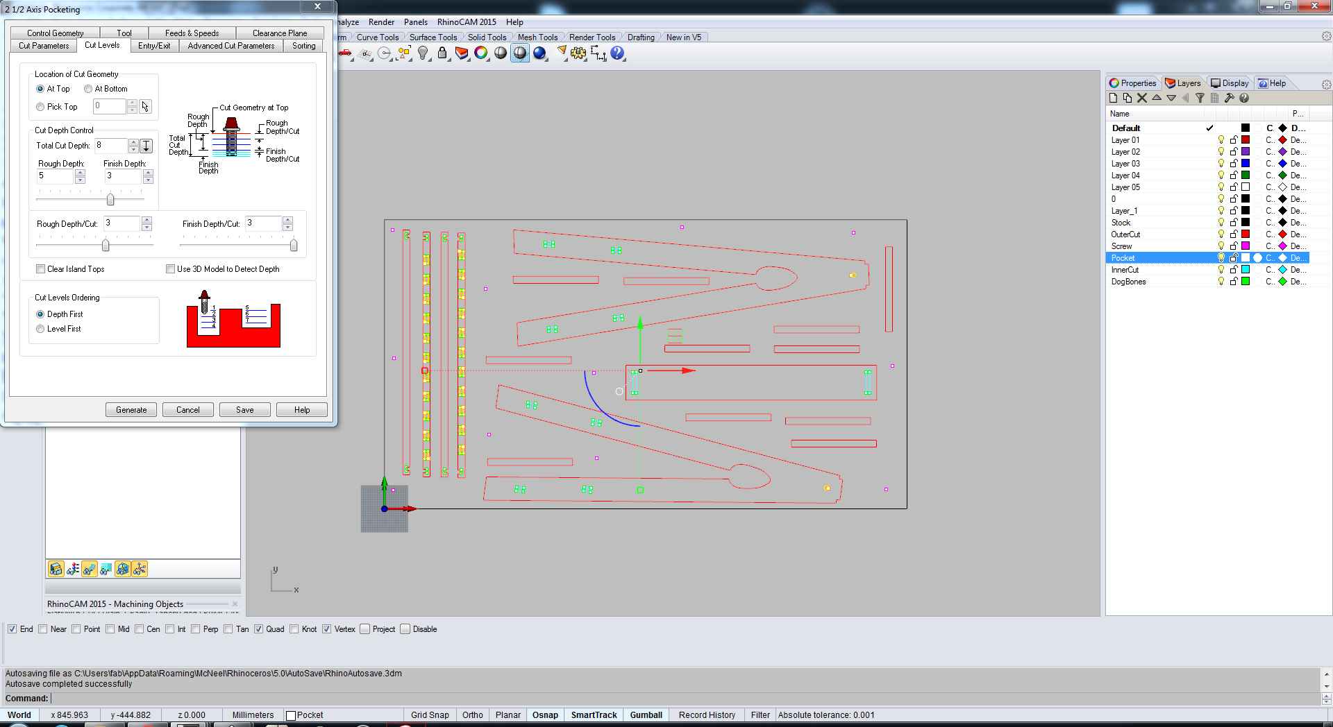
Pockets and Inner Cut scheme
Outercut
Pocketing and Innercut Simulation
Outercut Simulation
My Model ready for G-Code after all the layers has been added
Well for the part of G-Code, I was given a chance to go to "Valdaura - The Green Fab Lab", the G-Code was created using "Rhino Cam". There were a few steps to follow, first one was to create a scheme for each and every layer.
Once the G-Code files were ready now it was the time for the milling machine to mill my design on the Plywood which was quite easy.
Initially I thought I will go with the OSB material as it is recyclable as well as it was available in the lab in good quantity. So even if I failed an attempt I can try again, later on I changed my mind as the finishing on that material was not good, it was breaking quite easily in comparison with the others so I asked our instructor to order CONTRAXAPAT CALABO INT. XOP STD plywood, it is 5 layers plywood, quite strong in comparison with OSB and also it gives better finishing.
To start the milling, we have to start from uploading our G-Code files to the ShopBot to start and the press start to make it work.
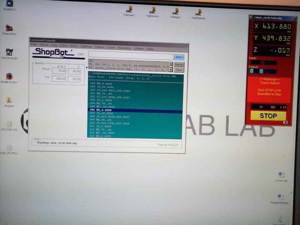
Uploaded G-Code for milling
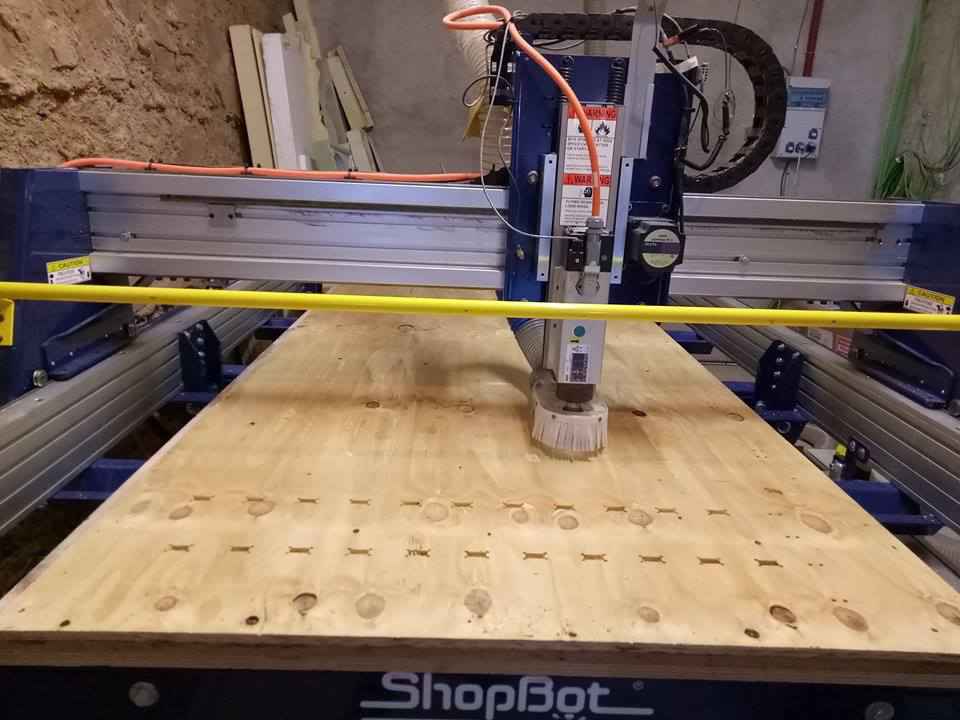
Shopbot Working
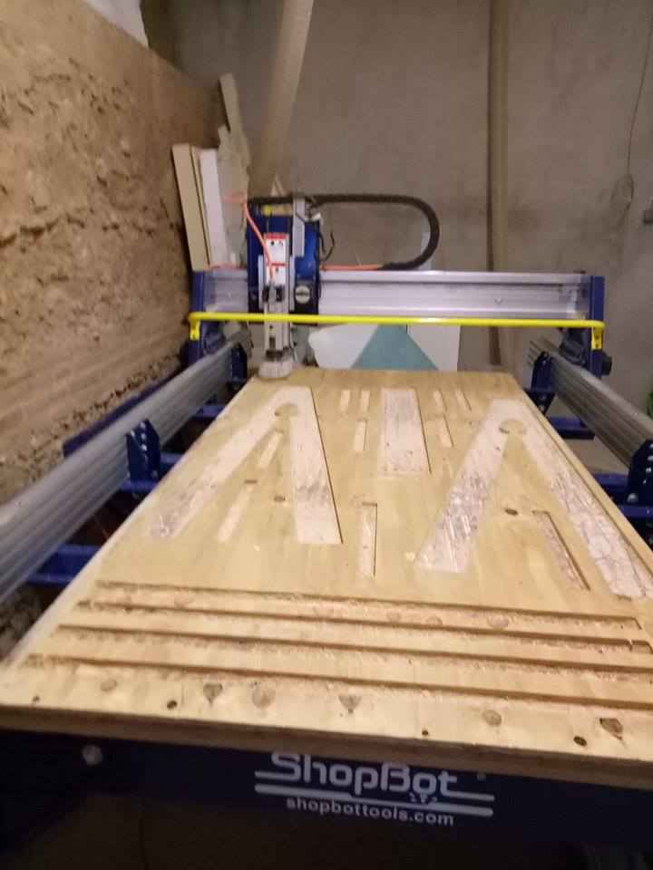
Shopbot Done
Once the shopbot was done milling, now it was the time for the assemble the milled parts
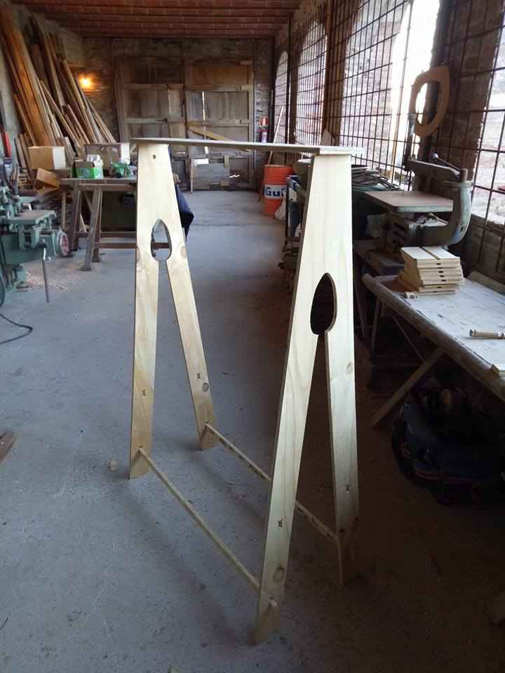
Assembling
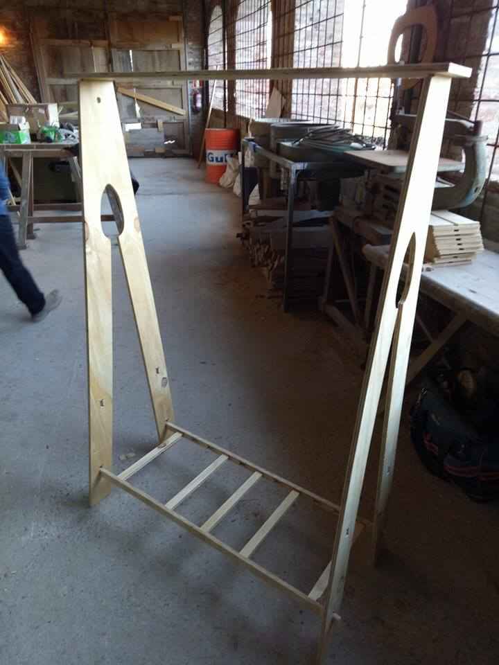
Hero Shot - Assembling completed
After the assmbling, I found a few issues with my design. One was the joints I placed with pockets, well they didn't work So I had to replace them with others which can be placed easily. Next the width of the connectors was too short and one of the connectors got broken.