This week’s task was an official challenge for a computer guy, I faced many challenges during the process, and as the process went on I learnt a lot of things and ways to solve those challenges.
I learnt the concepts of Electrnoics, soldering and the PCB designing (a total new and fantasy world for me).
To begin with, I had little to no knowledge of the electronics. Only the basic information I got from the elementary education.
So my first step was to search for the relevant info about the components.
I initially use to think that a microcontroller is type gate controller, where the opposite pins can communicate directly, but after getting the basic description of microcontroller, my all concepts broke like a Castle of sand.
“A microcontroller (or MCU for microcontroller unit) is a small computer on a single integrated circuit. In modern terminology, it is a System on a chip or SoC. A microcontroller contains one or more CPUs (processor cores) along with memory and programmable input/output peripherals.”
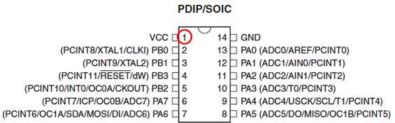
ATTINY 44 MicroController
A Zener diode allows current to flow from its anode to its cathode like a normal semiconductor diode, but it also permits current to flow in the reverse direction when its "Zener voltage" is reached
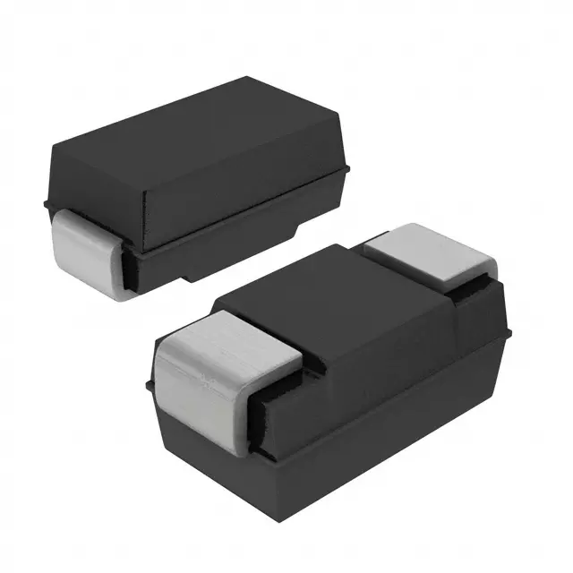
ATTINY 44 MicroController
A resistor is a passive two-terminal electrical component that implements electrical resistance as a circuit element. In electronic circuits, resistors are used to reduce current flow, adjust signal levels, to divide voltages, bias active elements, and terminate transmission lines, among other uses.

Resistor
A capacitor is a passive two-terminal electrical component that stores electrical energy in an electric field.
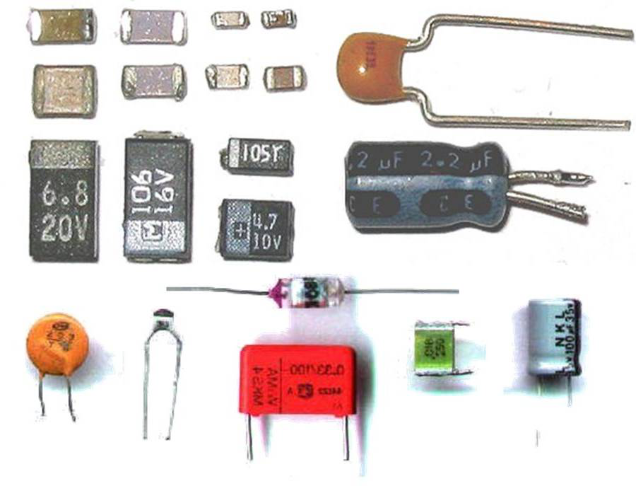
Capacitor
A crystal oscillator is an electronic oscillator circuit that uses the mechanical resonance of a vibrating crystal of piezoelectric material to create an electrical signal with a precise frequency.
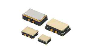
Crystal Oscillator
Printed circuit board milling (also: isolation milling) is the process of removing areas of copper from a sheet of printed circuit board material to recreate the pads, signal traces and structures according to patterns from a digital circuit board plan known as a layout file.
For this task we had to mill the MIT based PCB designed “programmer board”. Previously I had no information about PCB designing or milling. So this was the first challenge I had to face, like how to control or use milling machine etc.
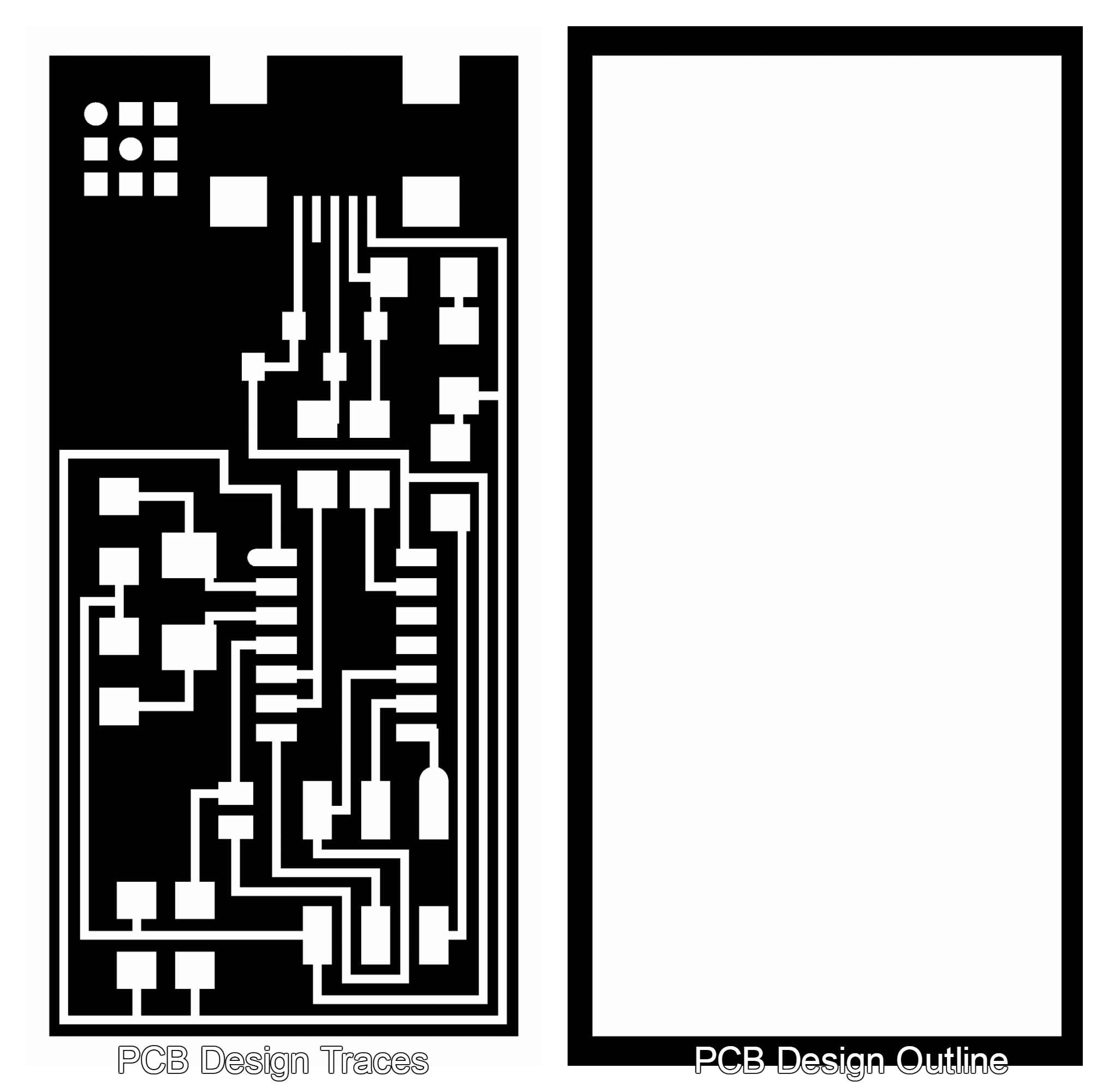
The Programmer Board PCB (traces and outline)
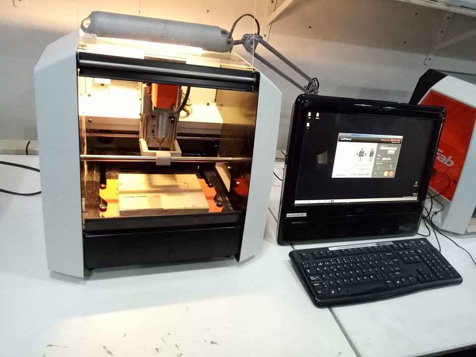
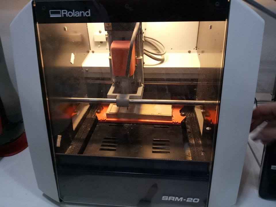
We had “Roland SRM 20” milling machine, so we had to convert these images to the appropriate code understandable by the milling machine. This task was quite easily solved, with the help of the “Fab Modules” by the MIT, which generates the code understandable by the variety of machines.
We can import images of traces and outlines and generate the machine understandable code
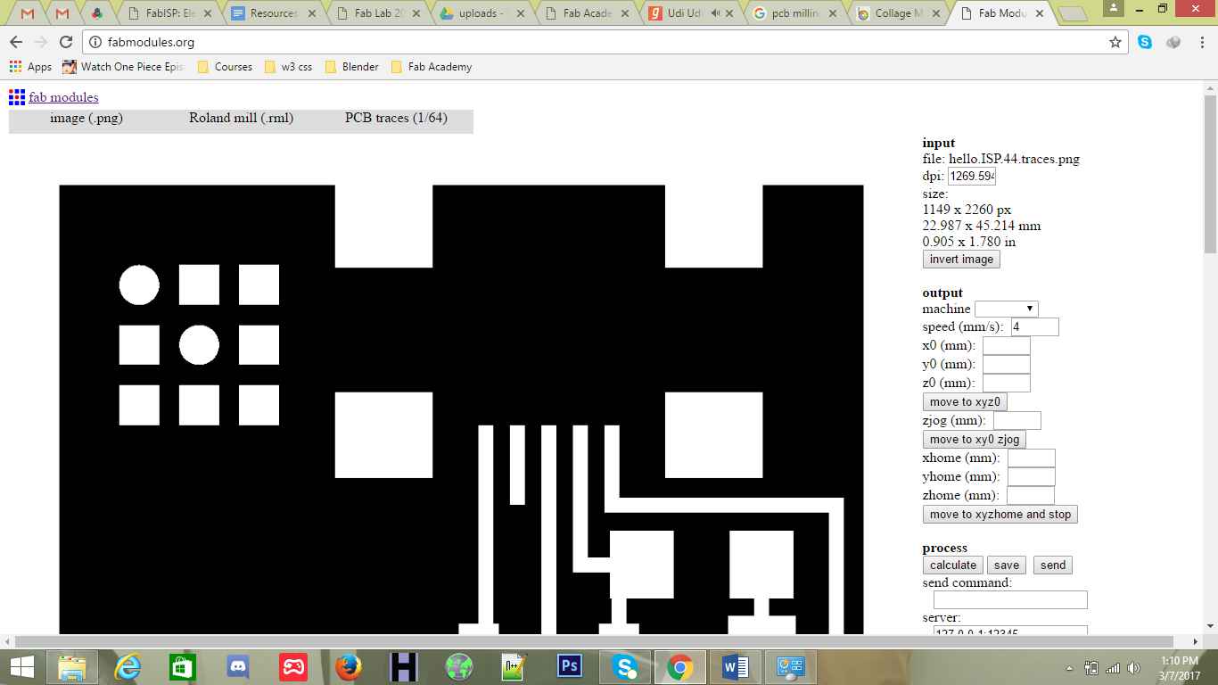
Fab Modules Settings
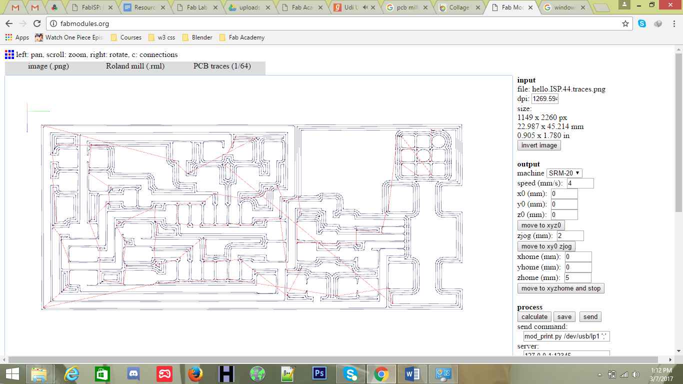
Fab Modules Settings for traces
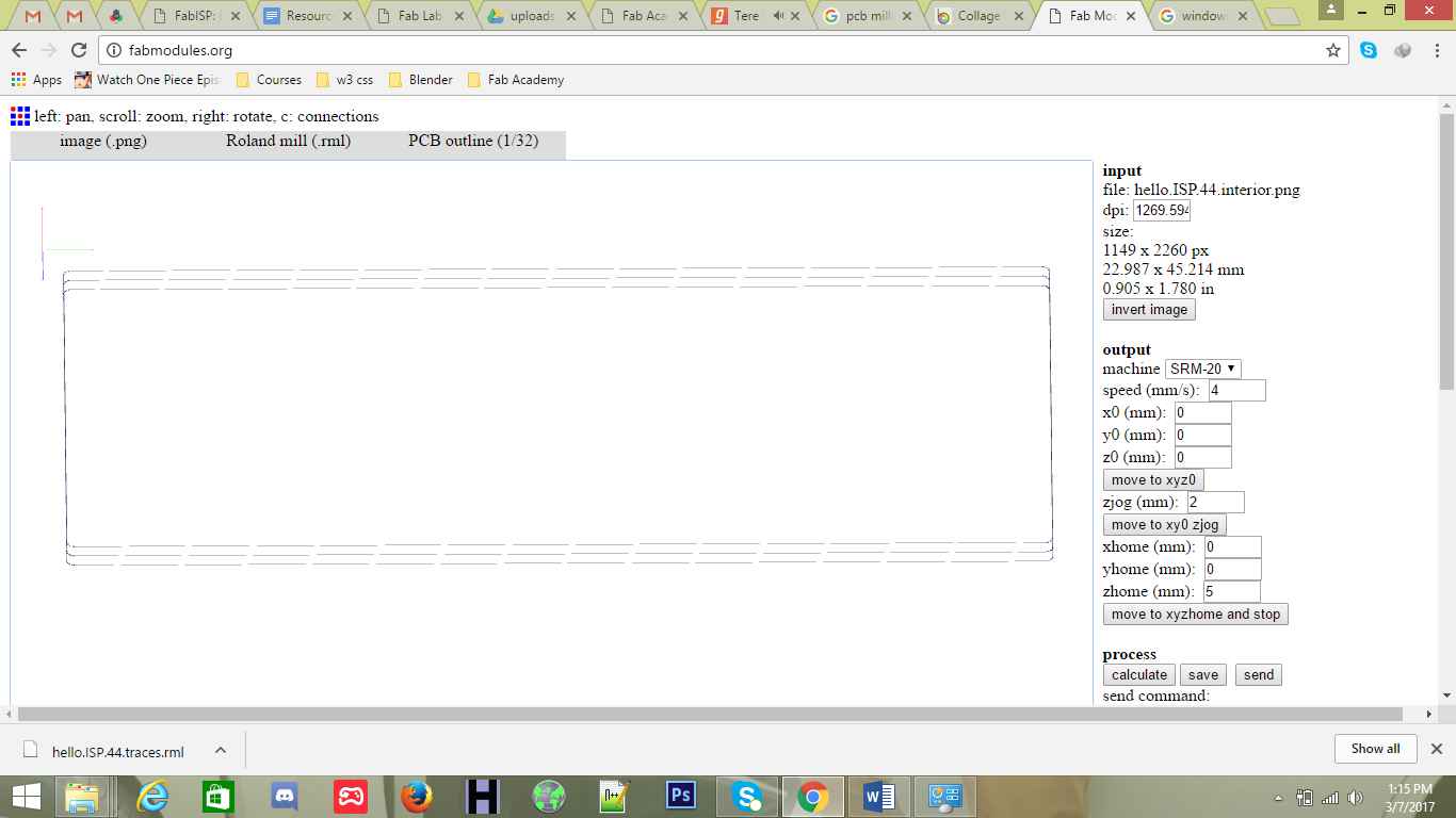
Fab Modules Settings for Outline
Now it was time to set the PCB board on the milling machine, with the appropriate place and alignment. After setting the board, then it was time to input the “traces.rml” file to mill the traces on the board
Setting the board to be ready for mill
Once the file is inputted, now it was time to set the X, Y, Z positions of the milling machine to appropriate positions, and the proper header pin as for traces 1/64 pin is used and for outline 1/32 pin is used, as the milling will start at our given co-ordinates and our selected header pins. If the co-ordinates are wrong our Board can be damaged as well the header pins.
Once everything was ready and checked, it was the time to start milling
Milling in process
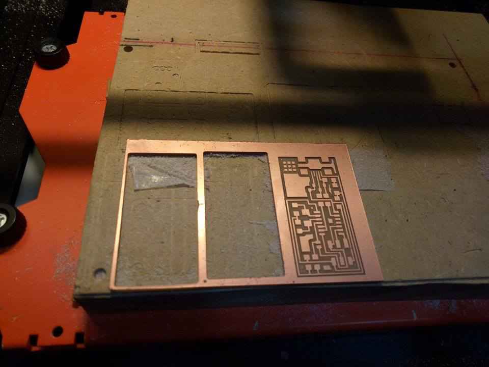
Completed Milling PCB
All the files are available to download and re-use
The most difficult task of this week for me was to solder the PCB board with the available components. But I can consider myself lucky, because the PCB I soldered, worked perfectly. First thing first, I made the list of components I need to solder my PCB.
First I made the list of components which will be used to solder the PCB. This is the complete list, attached with the all required components.
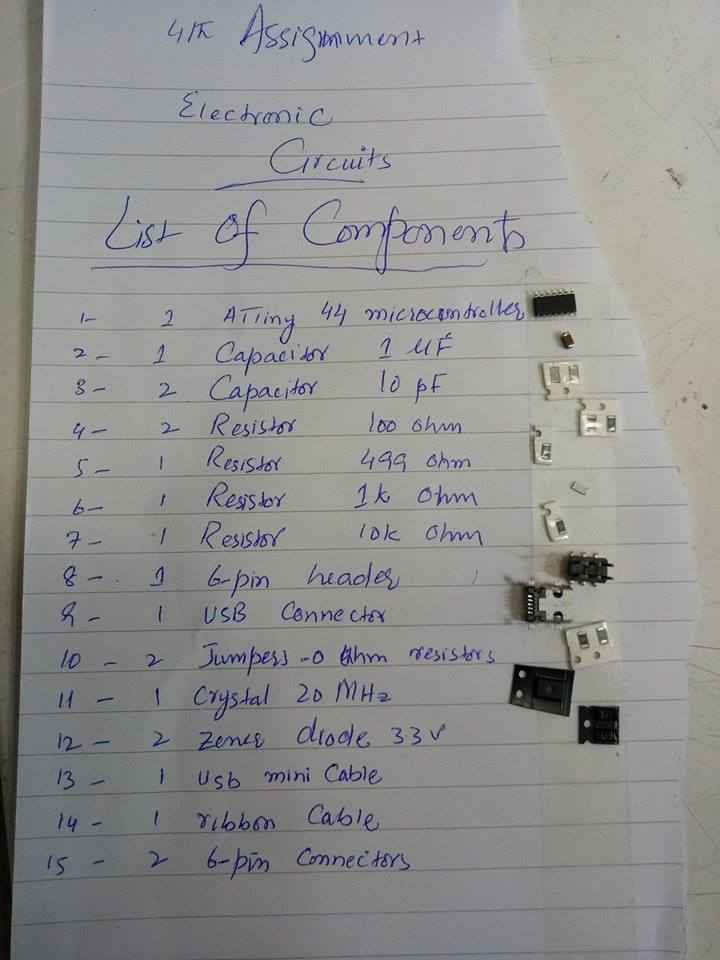
List Of Components to attach
Soldering is a process in which two more or metal items are joined together by melting and then flowing a filler metal into the joint—the filler metal having a relatively low melting point. Soldering is used to form a permanent connection between electronic components
First I made a few failed attempts to sold things as I was afraid that I might damage the board, slowly slowly I found myself adjusting to the soldering, and got into the flow.
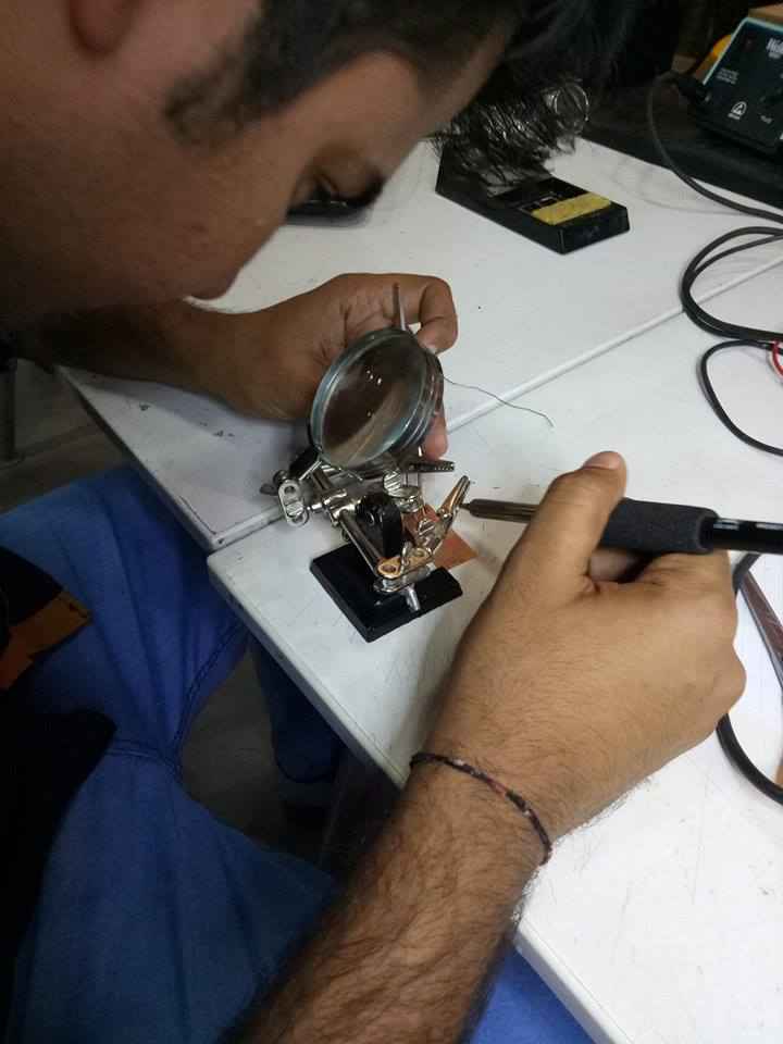
Soldering is just fun
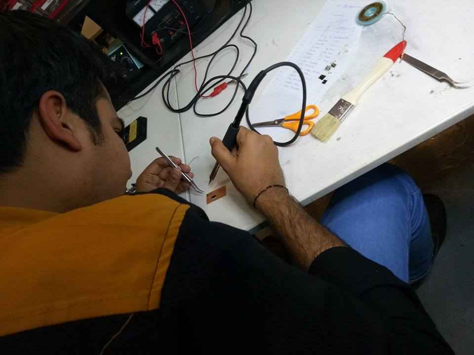
Soldering is just fun
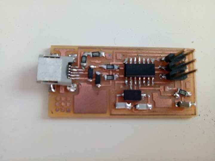
After hours of soldering, I finished my first ever PCB. I know it doesn't look good, but well it was my first attempt.
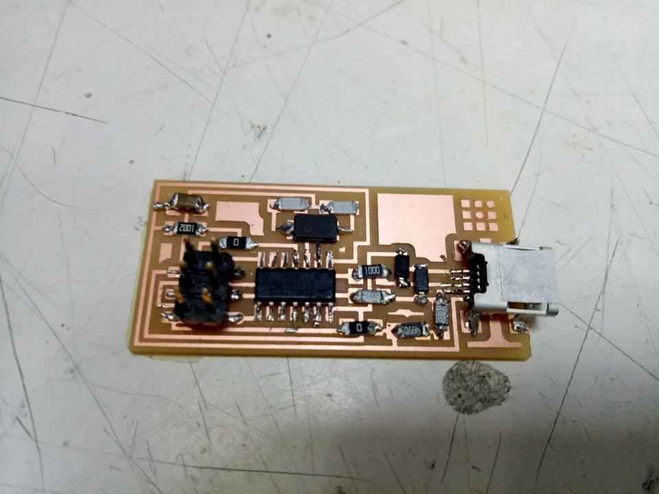
PCB After Soldering
Debugging is the process of finding and resolving of defects that prevent correct operation
I used Digital Multimeter to debug the PCB, I checked all the input and output connections of the PCB to see if all connections are working properly, and to my luck, they were working properly.
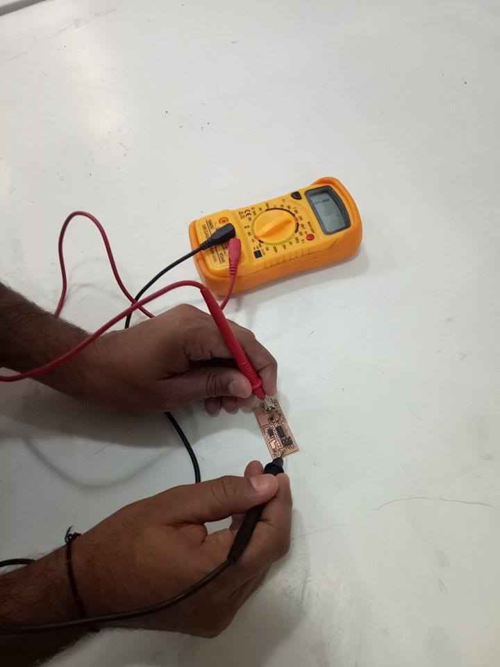
Checking the PCB - Debugging
Well during debugging, I checked all the ground connections of all the components attached, first ground to ground, then VCC to VCC so I can confirm that my all connections are connected properly. It clearifies the path of the current flow, and luckily my whole board was connected perfectly as I didn't found any issue.
I selected tasting tone point (continuity testing) of Multimeter, it beeps when two points are physically connected. If there is any missing connection it doesn't beeps.
Yeah, I was out of world, my first ever pcb and it worked witout any issue. I was really happy. I rechecked it on all the inputs and outputs to find any issue.
After the successful debugging, now it was the time of my favourite work, Programming....
Now it was the time to program it to see if it works. Now this task was also quite challenging (challenging, not in terms of coding but it wasn't available for windows), as I needed either Ubuntu or MAC to program PCB, well I tried the process to do it from “windows” but failed hard. So I asked a friend to help me out, and finally I started working on programming the PCB.
Step 1 - Install Necessary Software for AVR Programming
For the electronics units in the Fab Academy, you will need:
I followed this tutorial to follow and install the AVRDUDE (well unsuccessfully)
Step 2 - Power the FabISP Board
The board needs power
The very first step was to attach the PCB with the programmer and then to the computer, and check if the Green Light is on, if its on means my PCB is working perfectly
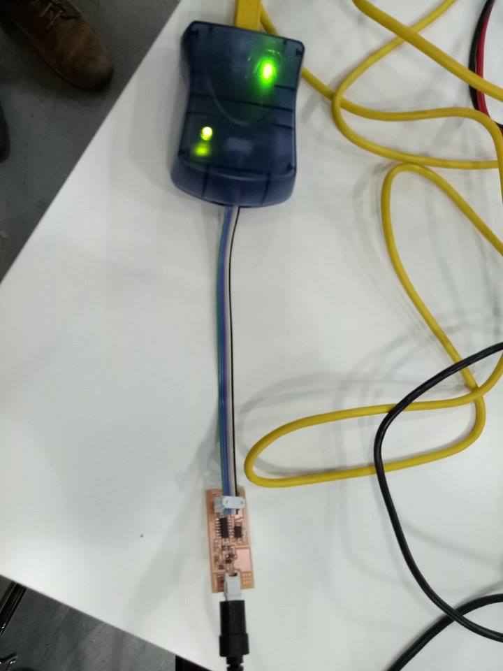
Checking if the PCB is ready to BootLoad
The light cautions and their reasons
Step 3 - Edit the Make File
The Makefile is in the firmware directory that you downloaded. The Makefile is set up to work with the AVRISP2 by default. If you are using another programmer, you will need to edit the Makefile.
I was using Mac: so Open the Makefile with TextEdit
Step 4 - Program the FabISP
Open your terminal / command line interface and move to the firmware directory.
Loading Firmware Directory
cd Desktop/fabISP_mac.0.8.2_firmware
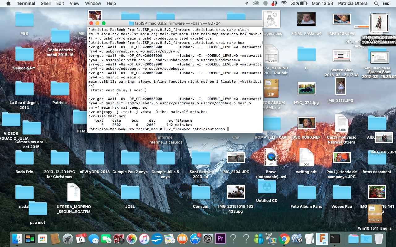
Next is to clean by using this command :
make clean
Next is to main command to make the hexadecimal file :
make hex
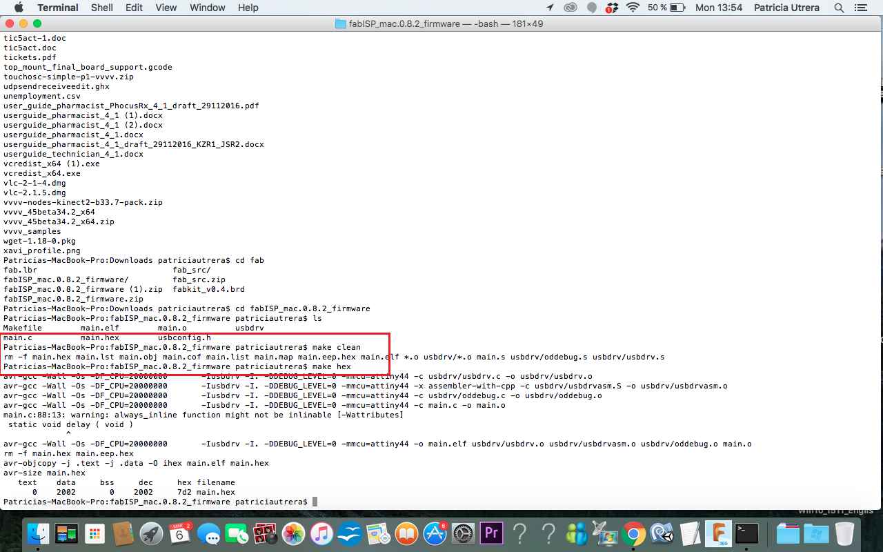
After Make Clean and Make Hex Comamnds
Next I needed to set my fuses on board to use external clock, type command :
make fuse
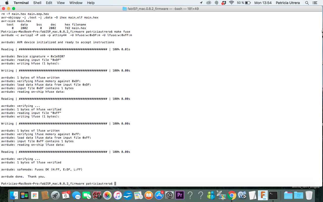
After Make Fuse Comamnd
Next I needed to program by pcb, type command :
make program
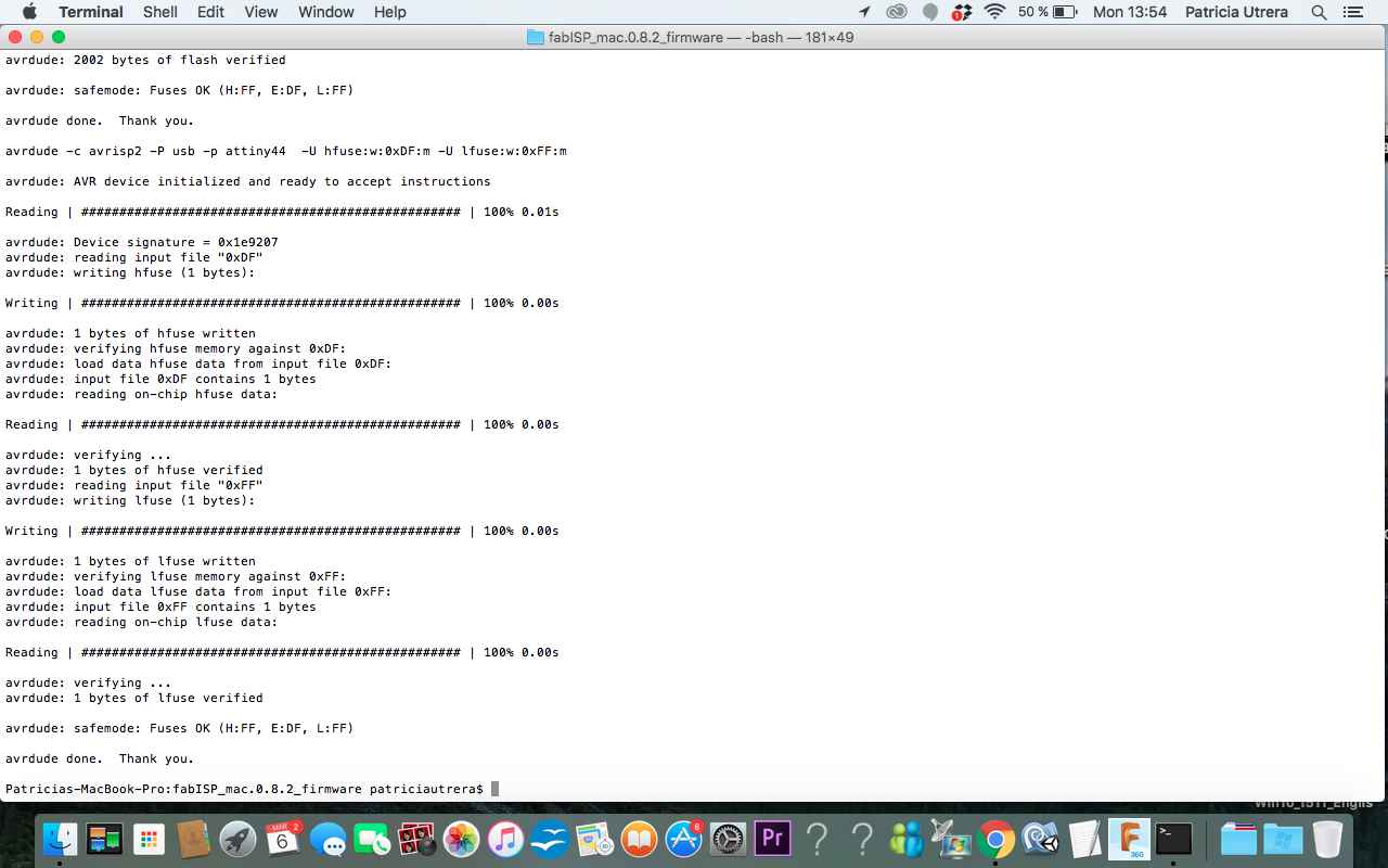
After Make Program Comamnd
Thats all for the programming part, if you have succeeded without getting any Red Errors as me you guys are surely lucky. Now the last part was to check if it is getting detected successfully.
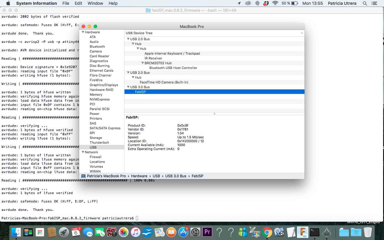
Checking the PCB if it is getting detected
Last but not the least, it was to desolder the 0 Ohm jumpers, so it can be used as the programmer when we need to program any circuits
Desoldering the 0-Ohm Resistors