
Assignment
- Group assignment: make lasercutter test part(s), varying cutting settings and slot dimensions
- Individual assignment: cut something on the vinylcutter.
- design, make, and document a parametric press-fit construction kit using lasercutter.
1. Laser Cut Group Assignment
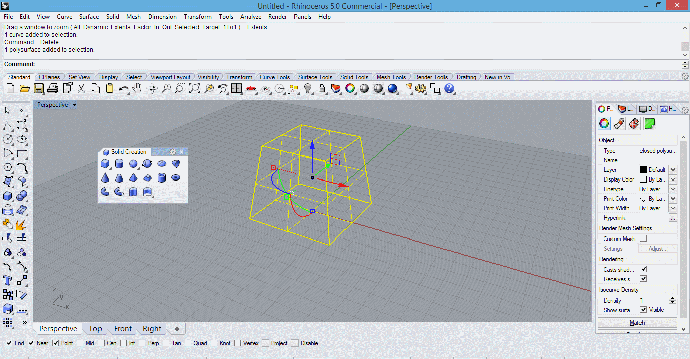
This was our first interaction with the laser cutting machine. We were very delight to know how useful this machine is in a variety of differnt ways. The object of this group assignment was to study the tolerence levels of the machine and to experiment with differnt values of laser power and speeds. For this assignment we made a basic pattern of rectangles. The parameteric design was prepared in Fusion 360 and then imported to Rhino in .igs format.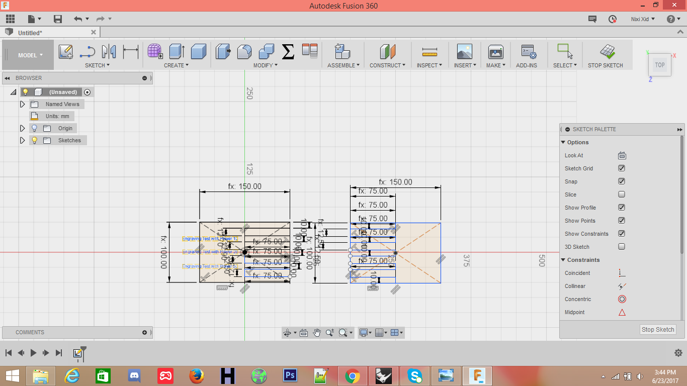
The file was imported is rhino and processed for laser cutting job.
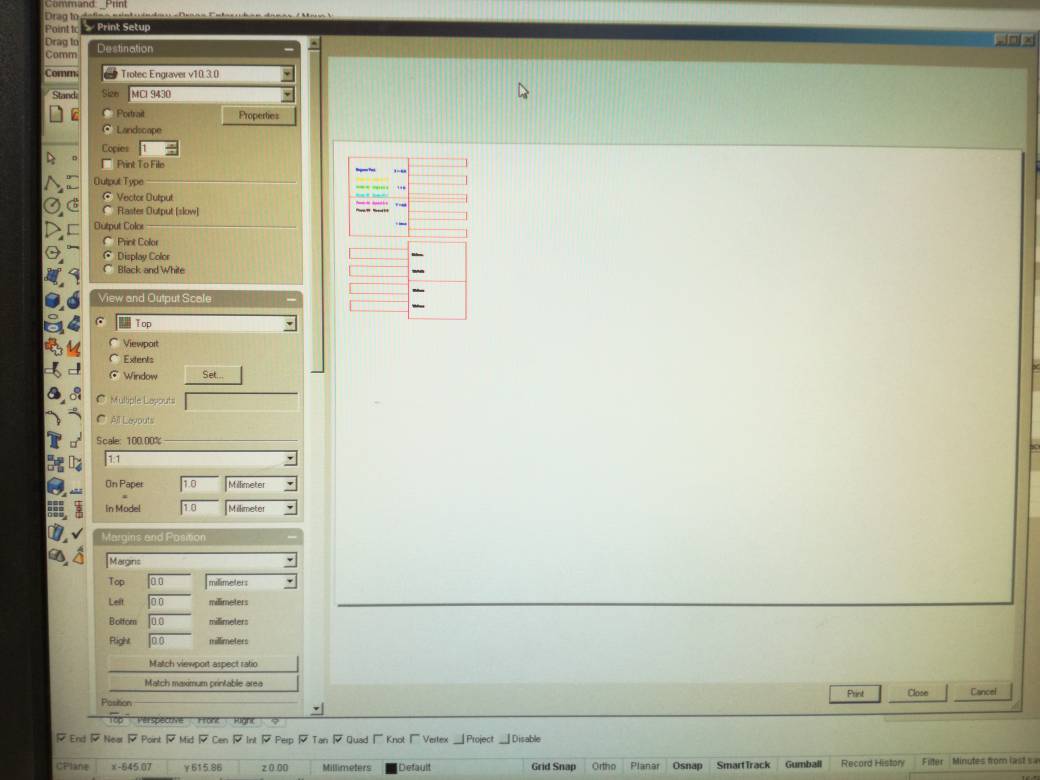
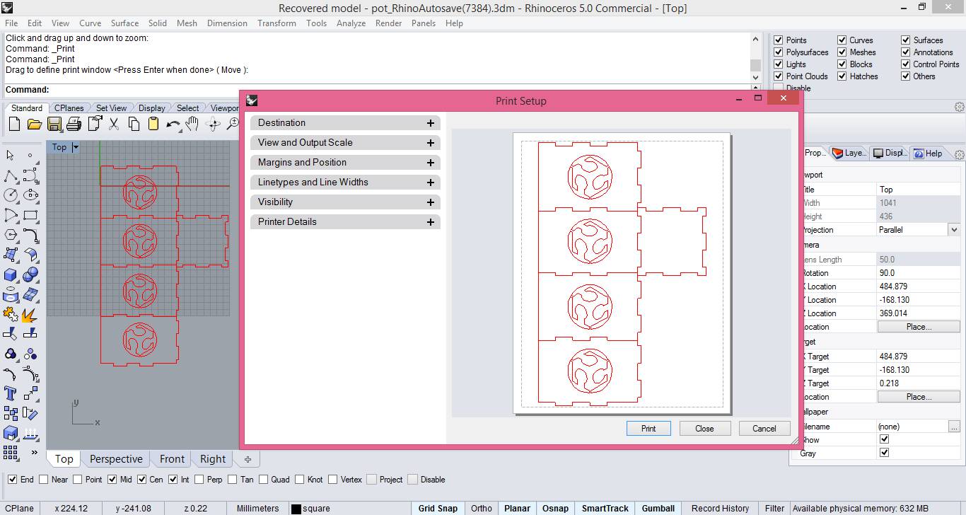
The job is sent to printer by simply clicking print icon. The print area and other properties can be configured using the following window.
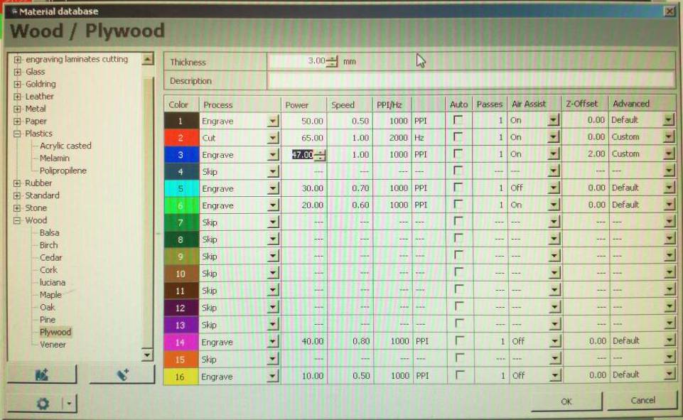
different objects with different printing parameters can be combined in a single job the of can be configure by placing the objects on different layers and assigning different laser power and speeds to each layer. The menu used for this configuration is illustrated below
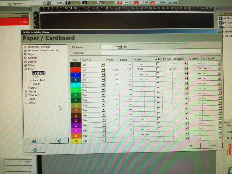
We started the print job by placing the stock on the print bed and setting the stock dimension in the Rhino Print options. Caliberation of laser z-axis must be performed with the help of metallic stub. After double checking everything print command was sent to the printer and it beamed away swiftly.
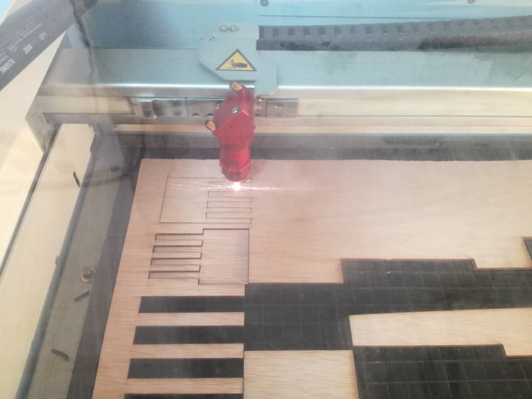
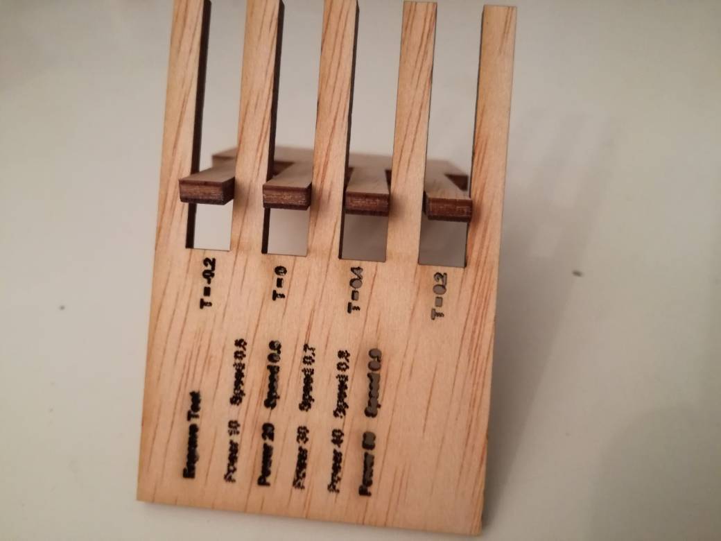
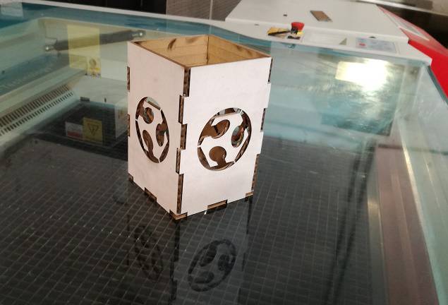
The Results
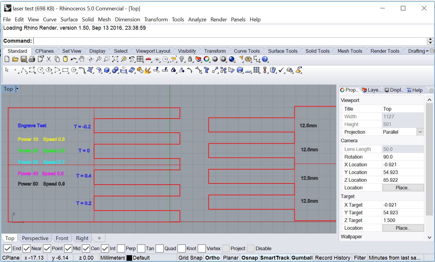
Following tolerances were considered -0.2mm, 0mm, 0.2mm and 0.4mm. The laser power cutting is set at 70. The results are illustrated below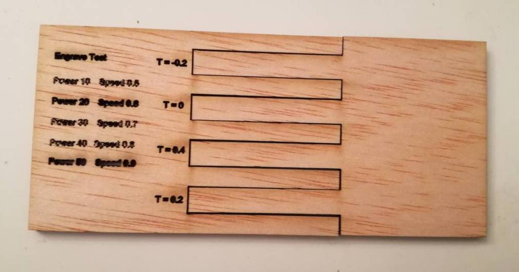
Since the tolerances are in sub millimeter scale the results are not prominent. However objects with lower tolerance would not fit tightly.
For engraving we tried different laser power and speeds. The results of engraving process are presented below
From our experience we come to conclude that although laser cutting is an effective way of cutting numerous items including paper, card-board, accrylic and plastics. However the laser power and speeds must be carefully choosen to avoid material melting or catching fire.
There are few terms regarding this machine that we have understood like the more power the more heat, and the more heat the greater the chance of fire. The speed you choose, determines how fast the laser will travel while cutting. The slower the speeds, the longer the laser sits in each spot, which yields more heat. It also means that the slower the speed, the deeper the cut or engraving will be.
2. Laser Cut.
- For this assignment I thought to make a 3d press-fit model of one of the signature building of pakistan.
- I start designing it in rhinoceros. I made the complete model by using solid, curves, boolean union and subtraction. we can see all these steps in the gif image given below.
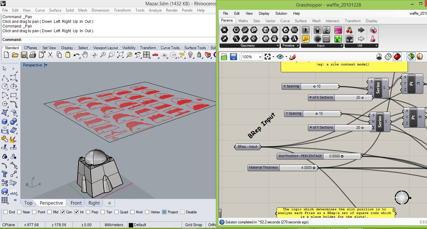
- At this stage the model is a non parametric solid, to make it a press-fit parametric model I can used grasshopper. for that i found this (http://www.grasshopper3d.com/forum/topics/a-solid-waffle-for-laser) link really useful. on this link we can find a waffle grasshopper script to make a laser cut press-fit model of a solid.
- I found the following tutorial which explain how to use the waffle script.
- When the first time I use this script i made spacing two narrow and made 40 pieces (20 for each axis) as shown in the image given below.
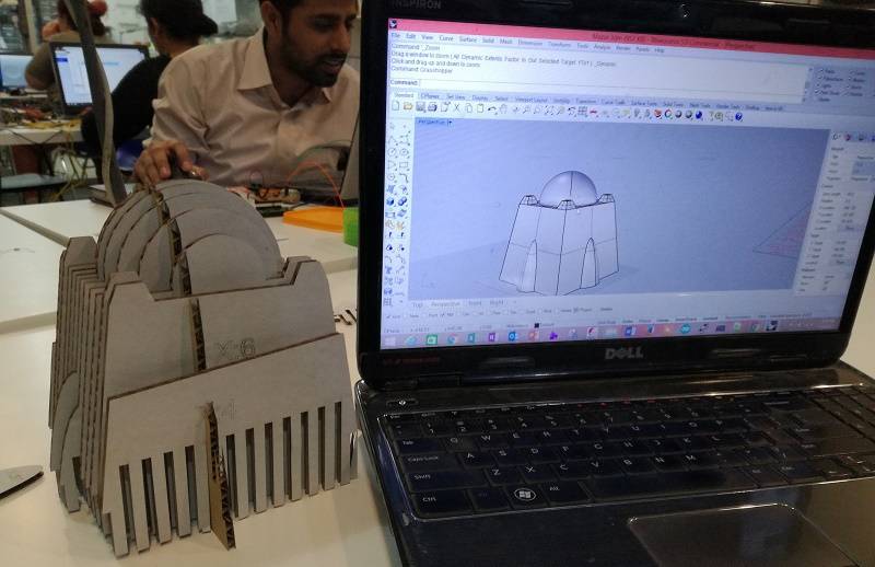
- After creating two layer, one for cutting and other for engraving for text on the parts, I send it to the lasercutter.
- Following is the videos shows the lasercutter cutting the pieces.
- Parts was really accurate, i just wants to assemble them.
- At this time I realise that the parts are too closer to each other, I need to decrease the number of parts of the model.
- Some how I manage two put almost 60% of the parts, now the model take its shape, but after this I was unable to connect more parts, becuase I was using cardboard and its edges are like fragile and its broken.
- Now I am thinking to try anyother parametric software and do something else.
- This time I have design the object shown in image given below, in fusion360.
- First of all I start designing it from the base.
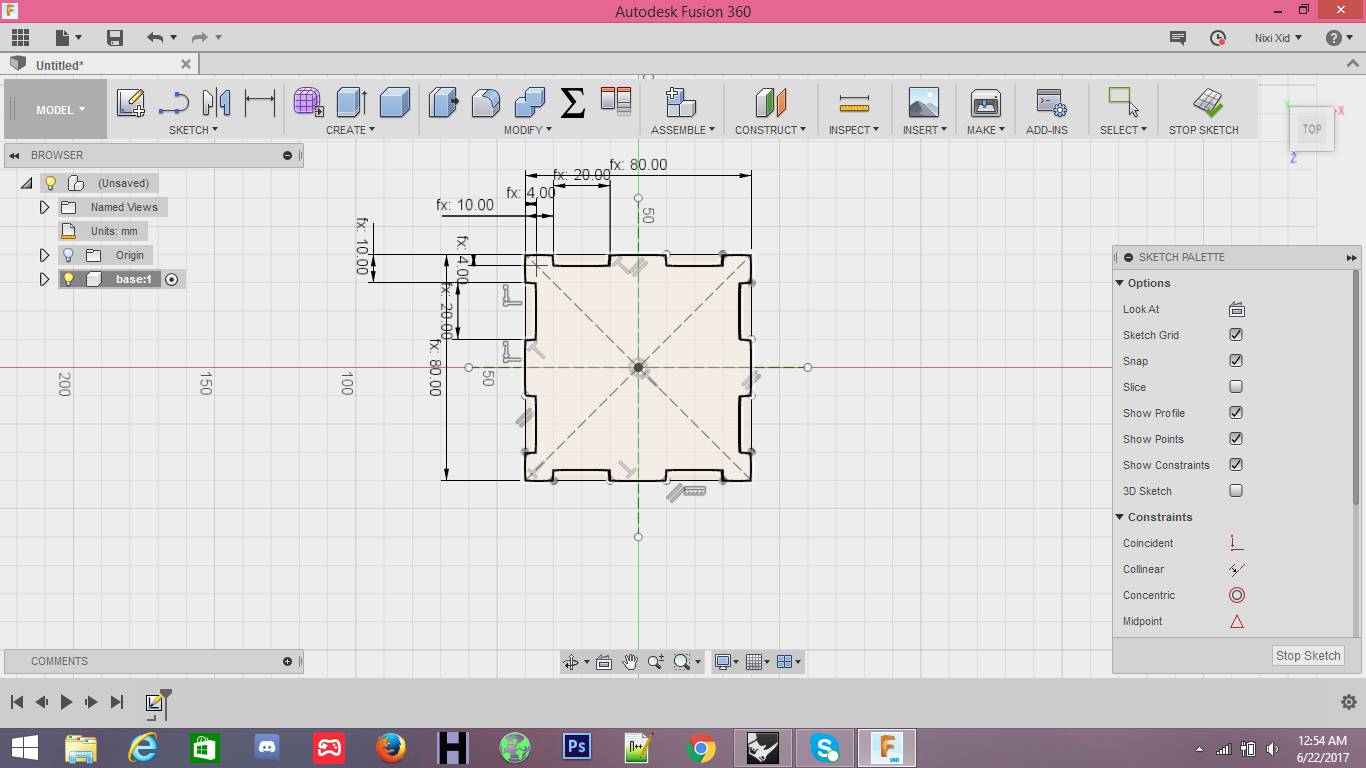
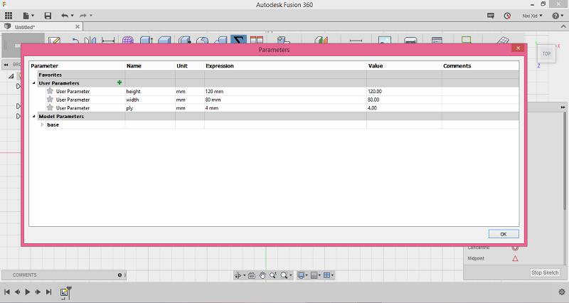
- Parameters
- Now the first side.
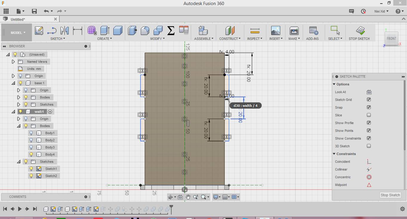
- And the second side.
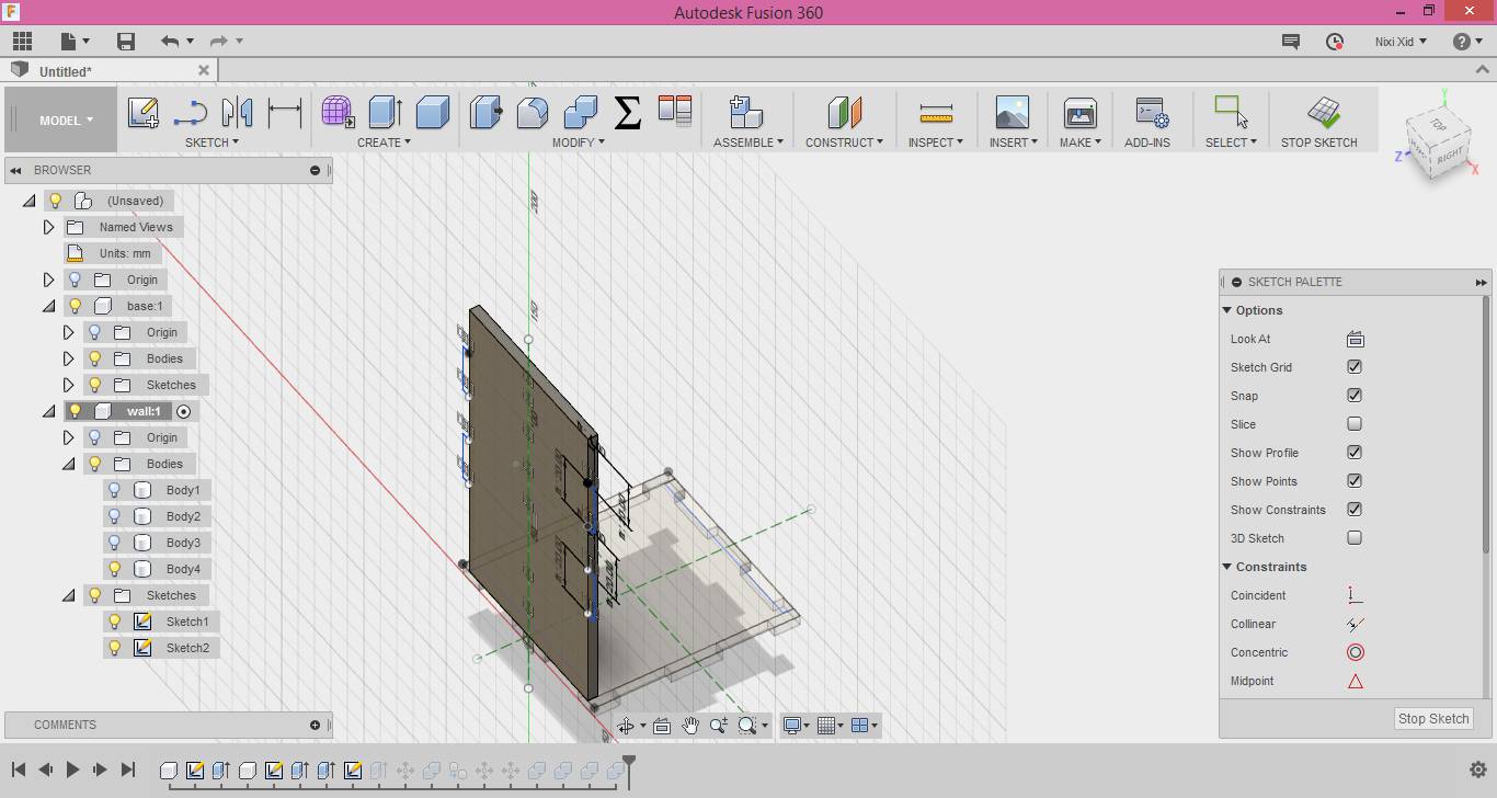
- And the other two side of the model are symatrical.
- Now export the file to Rhinocerous for cutting.
- After adding the fablab logo arrange all the parts in order to cut.
- Second the file to the machine to cut.
- Video while cutting
- Finally, I am done. :)
Second attempt.
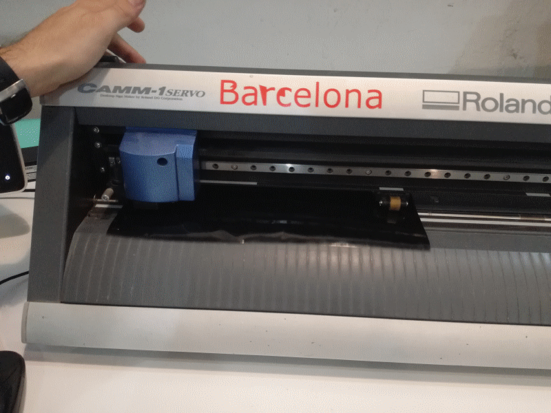
3. Vinyl Cutting.
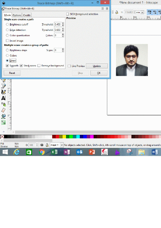
I would like to cut my black and white picture. For that first I need to flow the following steps in inkspace.
- Import/open the picture in inkspace
- select the image and to the "Path" and then "trace bitmap"
- Now a window while be open, from there select the "Gray" at the bottom left of the window.
- Now ungroup the image and you while find many gray scale copies of your orignal image.
- Select the most appropriate open, or the one that you like.
- Now to make it complete black and white from gray shade just select the picture and change the colour to black, and your done.
- Now as we know we need line to cut in vinylcutter so we need to get the outline of the image, we can get it easily with trace bitmap and then stoke in inkspace. Now the file is ready to go for cutting.
All the above steps are show in the gif image given below.
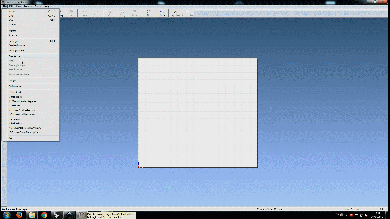
- Now open the cutstudio software of vinylcutter and import your file.
- Insert the material in the vinylcutter and you will see the dimensions of the material on the small screen of vinylcutter
- Now from software (cutstudio) set the size of "material from File --> cutting setup --> properties --> size --> get from machine" these steps are shown in the gif image below.
- And send the file to cut.
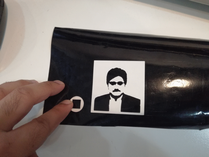
- Removed from material and pasted on my laptop.
Download All file of this week Here

This work is licensed under a Creative Commons Attribution-NonCommercial-ShareAlike 4.0 International License
.