

I'm going to design and build a network based on serial asynchronous communication.
I'm making one bridge board and two nodes.
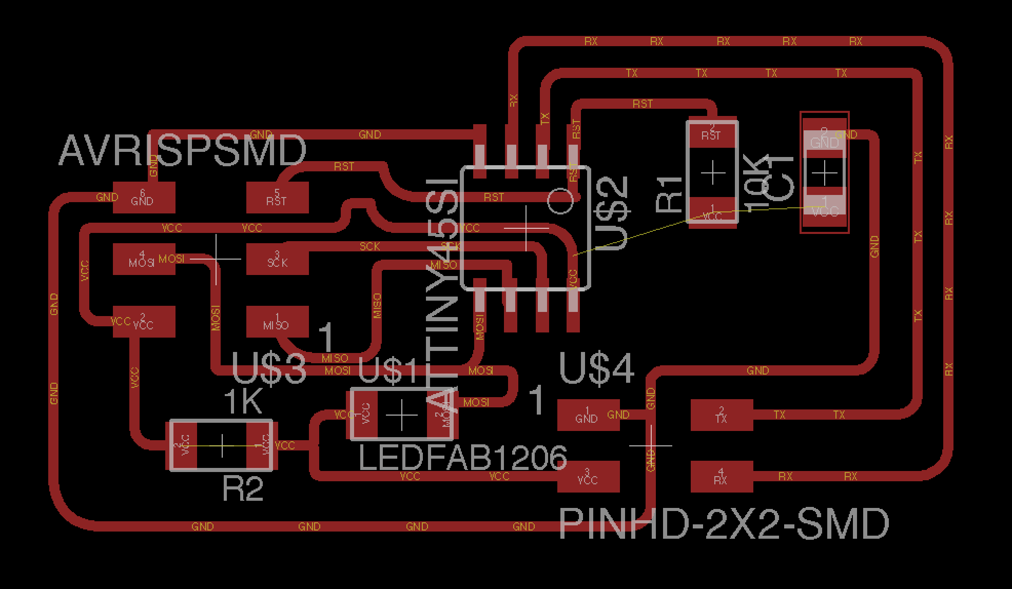
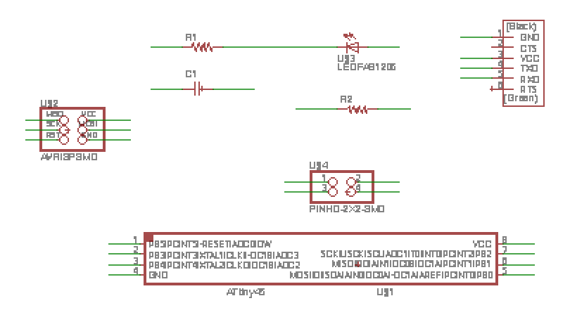
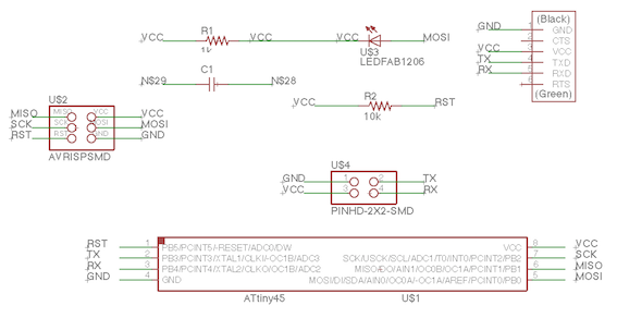
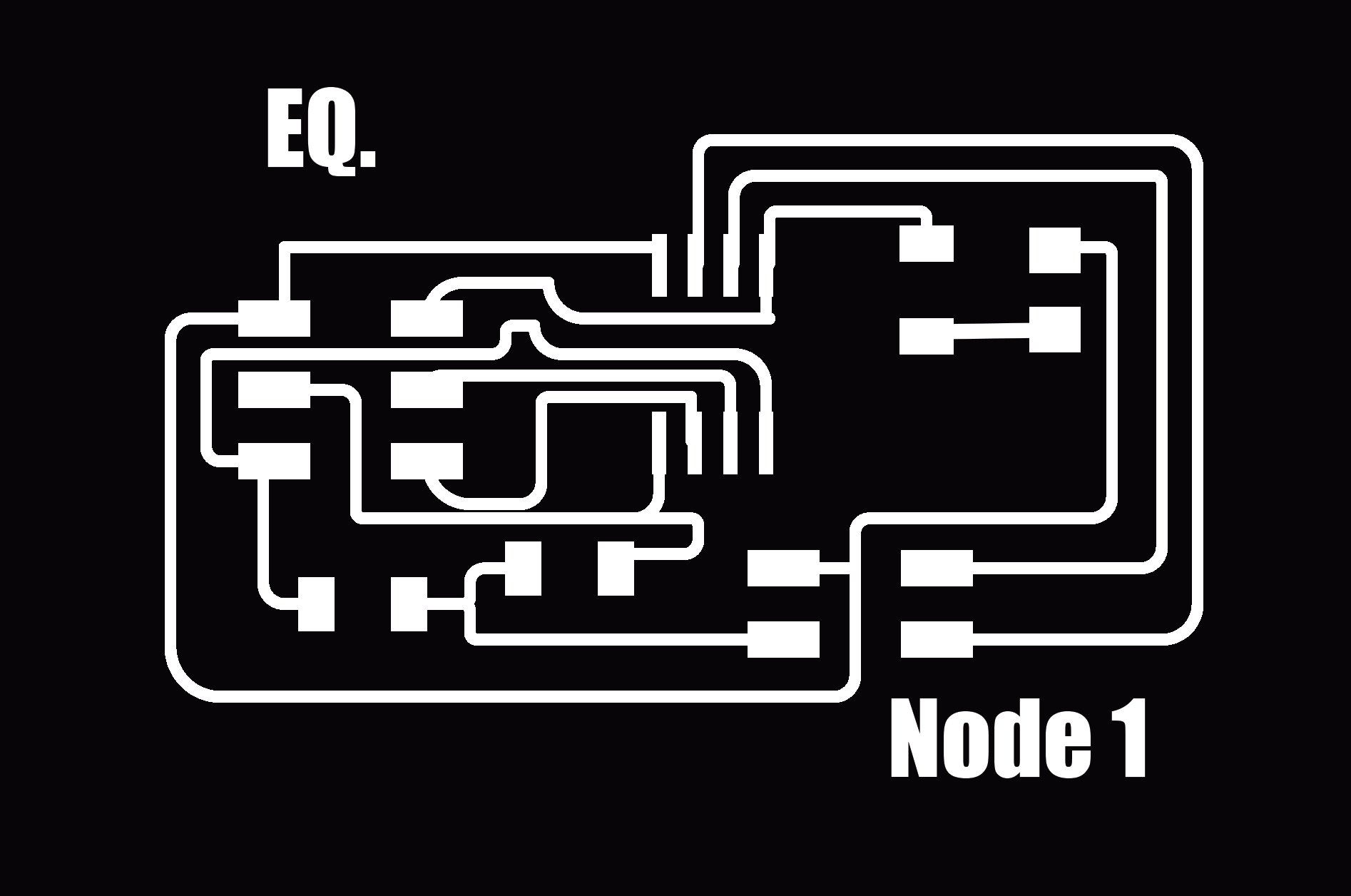
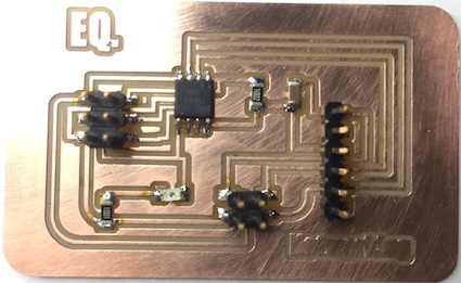
This is the first one and is the bridge board.

And now the node board. I milled two of these.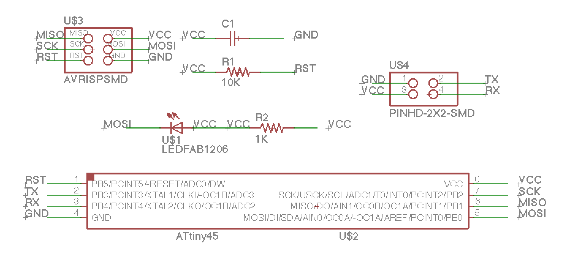

The Mill, Baking the mix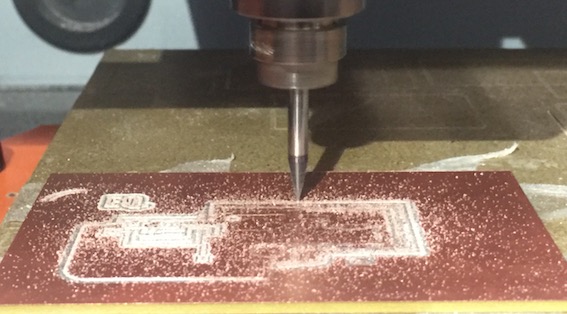
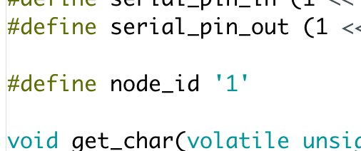
BRIDGE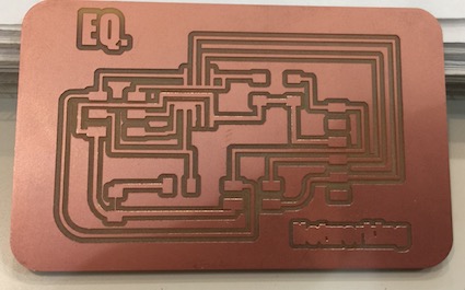 The diference between the Node 1 and 2 is the number of offsets, in the firstone I used 2 ande in the secindone 4.
NODE.1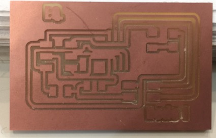
NODE.2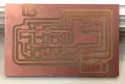
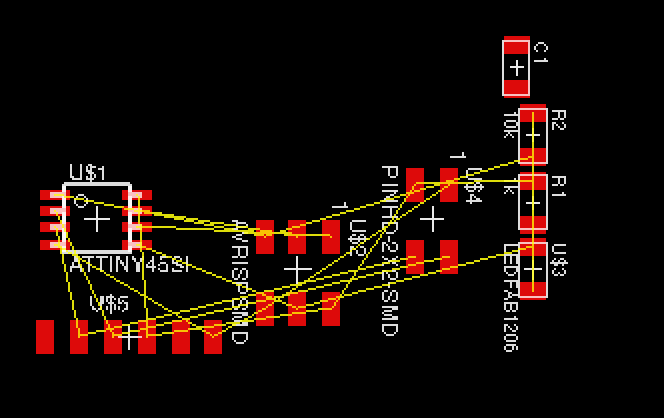
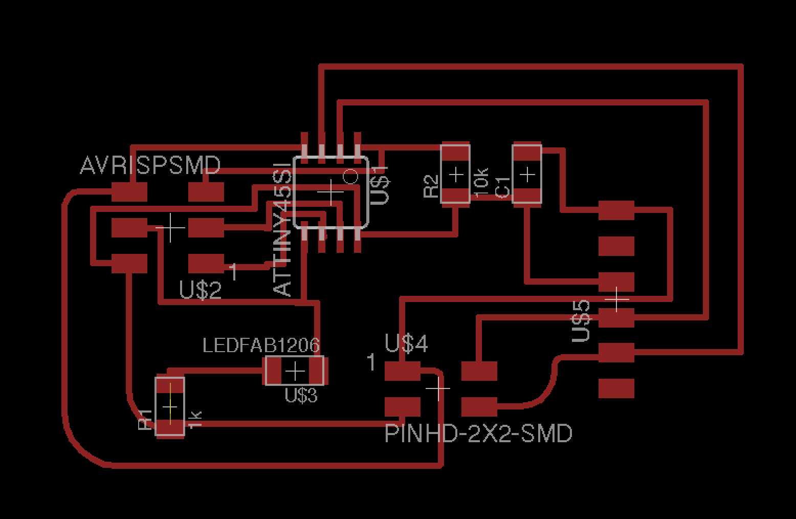
Bridge traces Bridge Outline
Node traces Node Outline
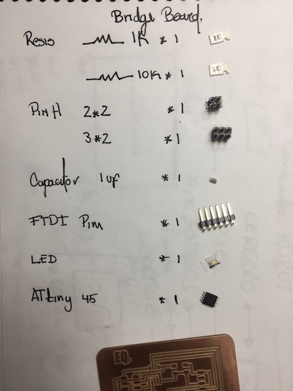
BOM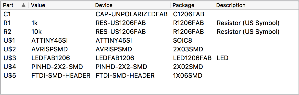
To programing each one of my boards I connect one by one to my ISP and then use the code from Fab Academy website. Code.But with the nodes I had one problem that with Tomas we find. this is.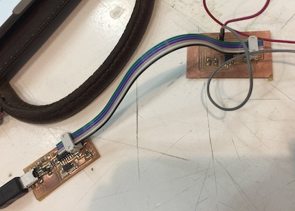
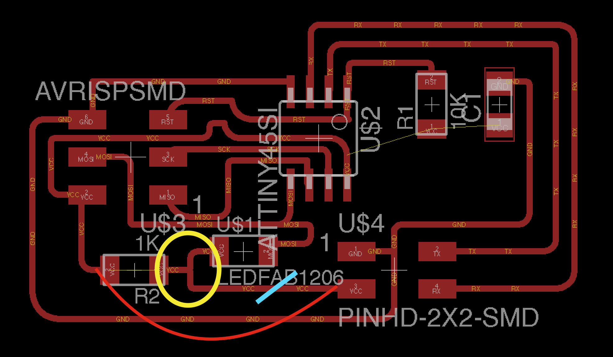
The yellow line is the problem, I the energy was cut, so I cut the trace in the blue line and did a bridge with a cable.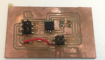
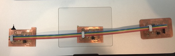
This are the boards connected to the network.
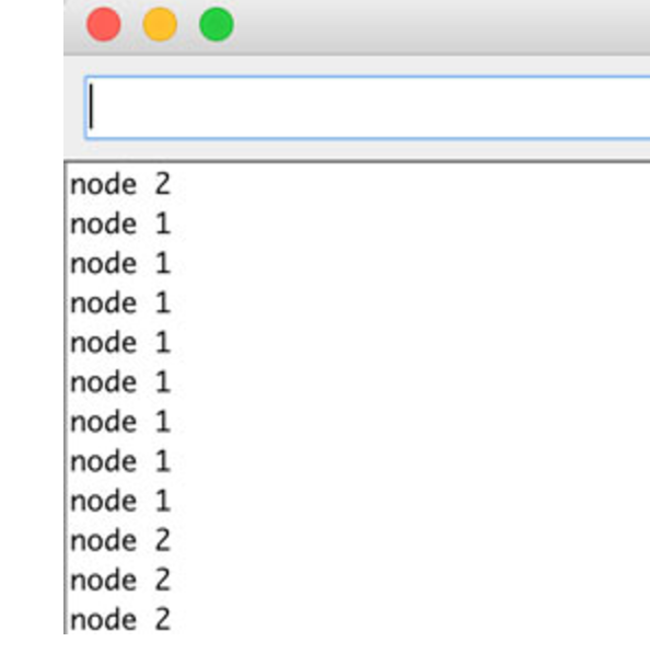
Next, you load the Arduino IDE, and click on the Serial Monitor button. On the Serial Monitor window you type 0, 1 or 2 and press enter after the node you typed. Then you should get your boards react. The node selected should blink twice and get a response on the serial monitor window.