Date
6th week
CLASS
Electronic design
Eagle and basic electronics
in this week we been asked to design our own board based the echo hello-world board and add a button and LED. for starting with this assigment we had to play and learn how to use eagle, add component and design in schematic mode and then in the board mode design the traces and components postion. following step by step guide was provided on the calss documents i started with adding the requiered components to re-write the hello-world board.
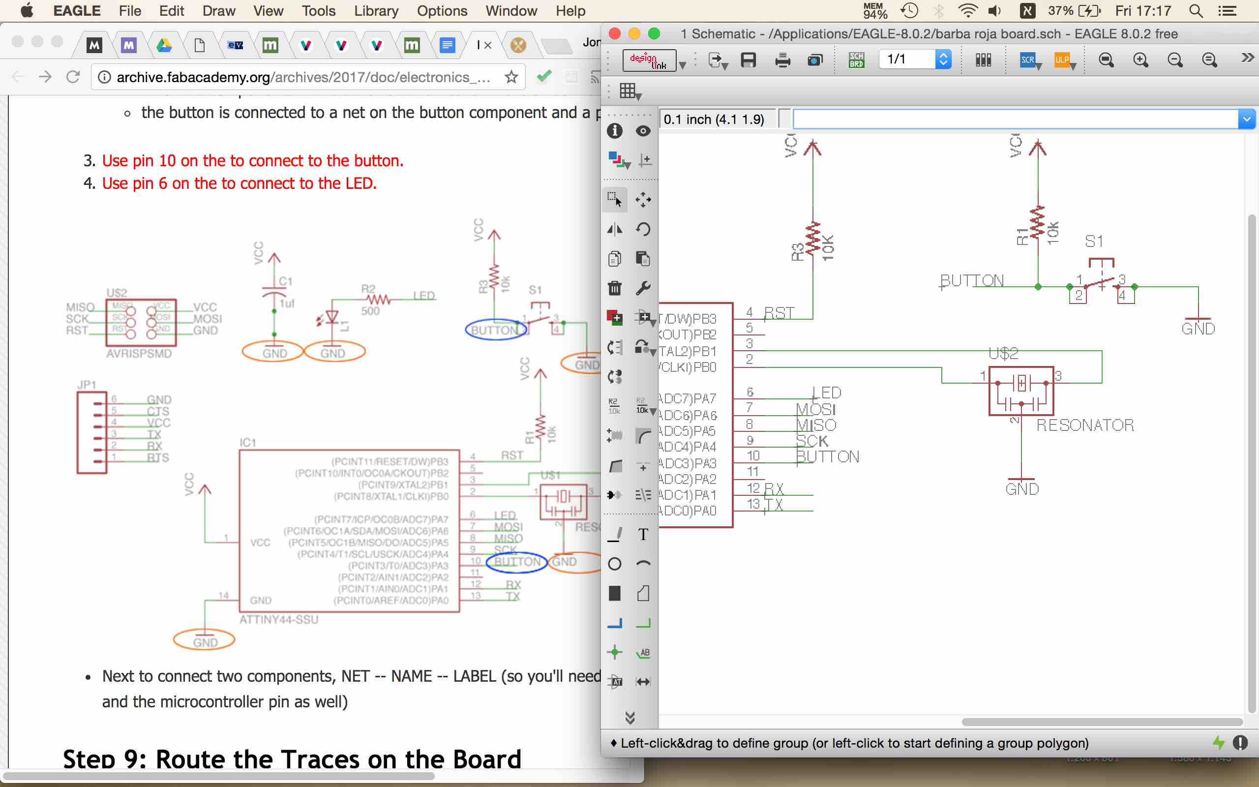
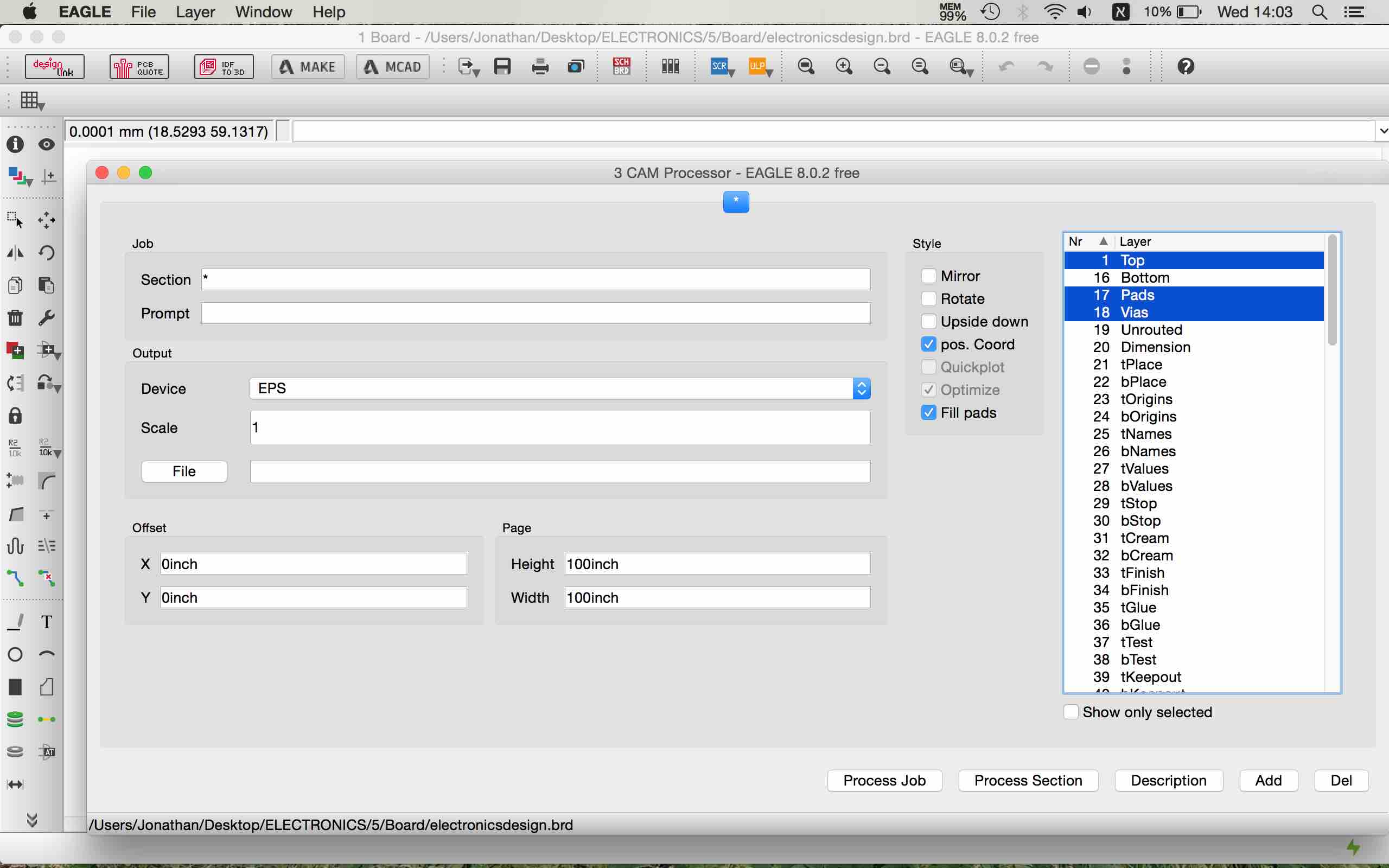
After getting famillier with the ways to connect components on the schematic mode i made the connects needed from the ATTNY 44 to all the ather component as showed in the toturial.
when finishing with that i changed to board mode and saw all the componant symbols with a yellow line that connect between them for showing me how to route the traces.
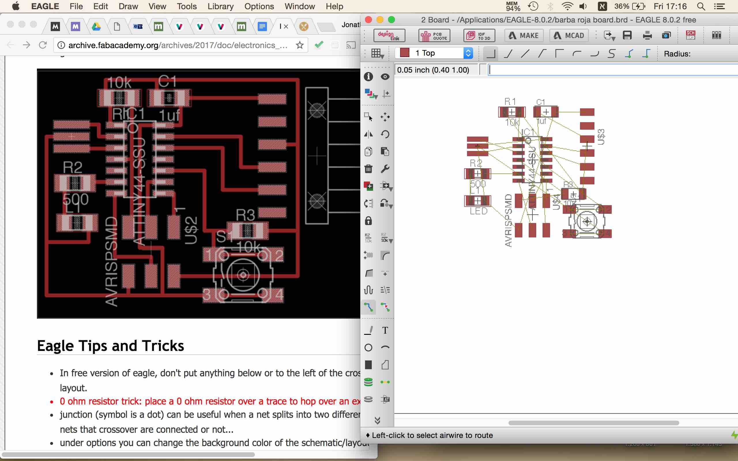
i organized them in the same way as i saw on the toturial and started to mark the traces between them.
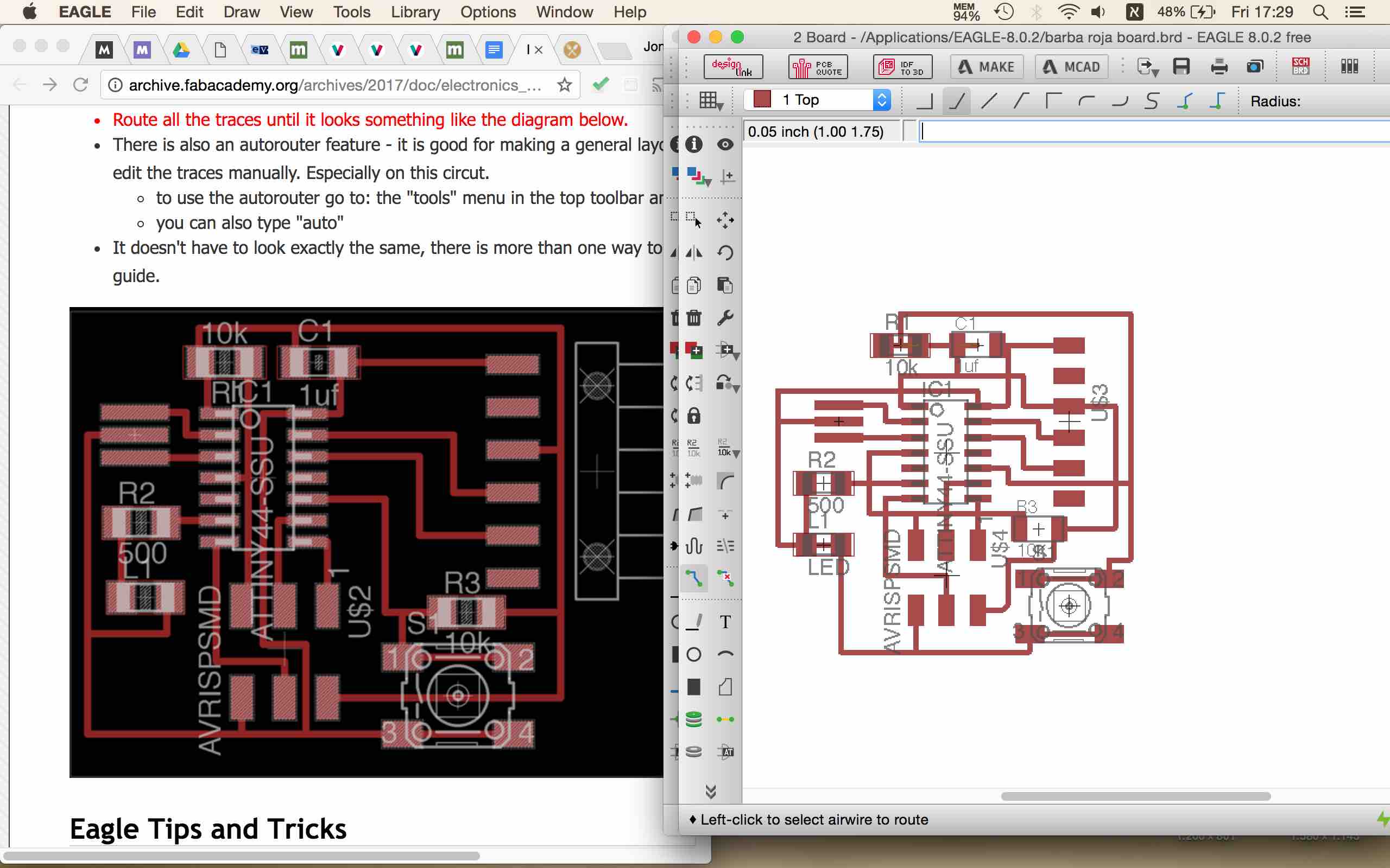
after doing that i decided to give it a bit of style and explored to way i could do the traces a bit nicer still keeping the same rules between the components.
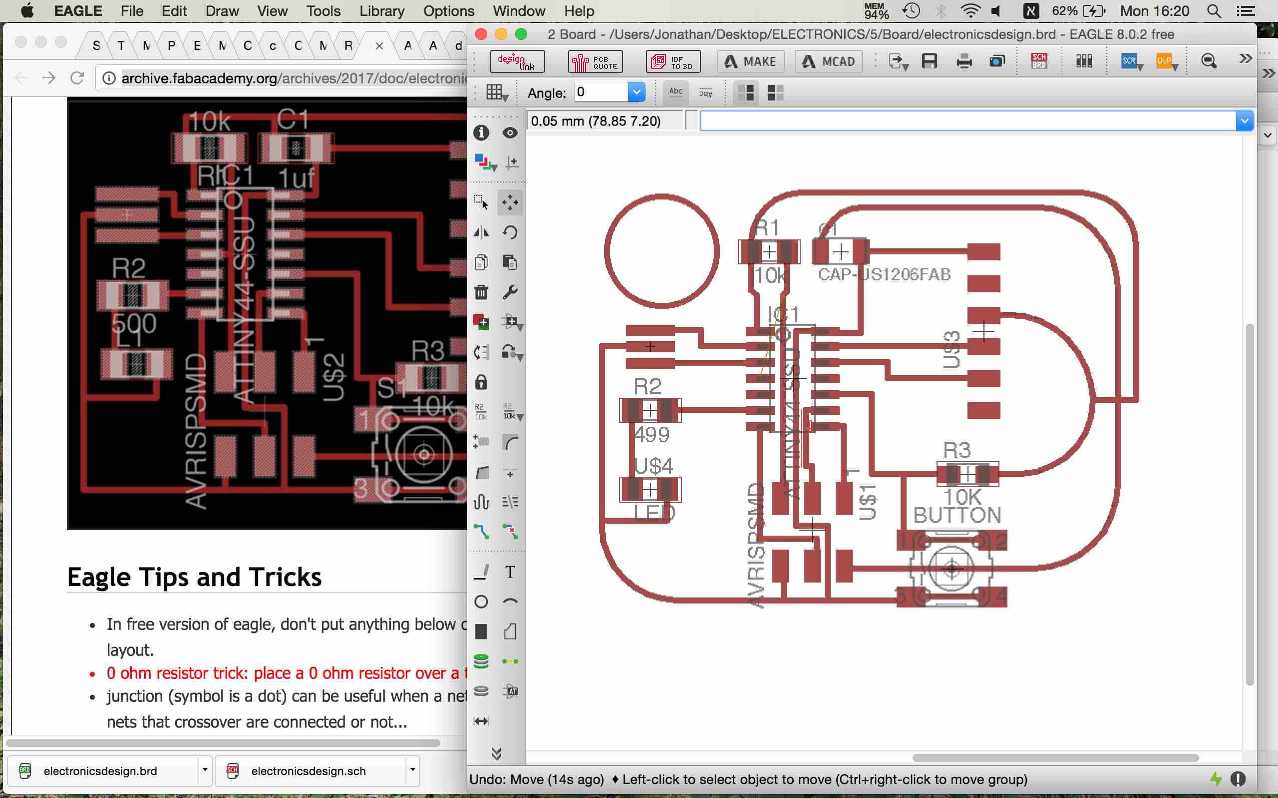
An hour later and some curved traces lines i got satified from the result and started to check clearance between the traces and he components. one by one moved the components and the traces to avoide clearance and have to say that in some parts it wasent easy and needed me to play with 0.001 mm movments until i got a clear clearance alert window.
having that done i viewed only the layers i needed for exporting the png file, in that way when opening the file in photoshop i got a double sized image then the real size of the board, i noticed that some of my class mate had the same problem and the solution was to export it was to go to the CAM processor and export it as a EPS file
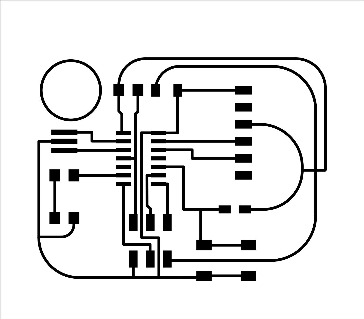
I used photoshope to convert the traces to black as i needed to use the fabmodulse site that read the png file like that and as well to create the outline of the board. after having the both png file ready i uploaded them to the fabmoduls site and to calculate and create the needed file for the SRM20 Ronald miling machine.
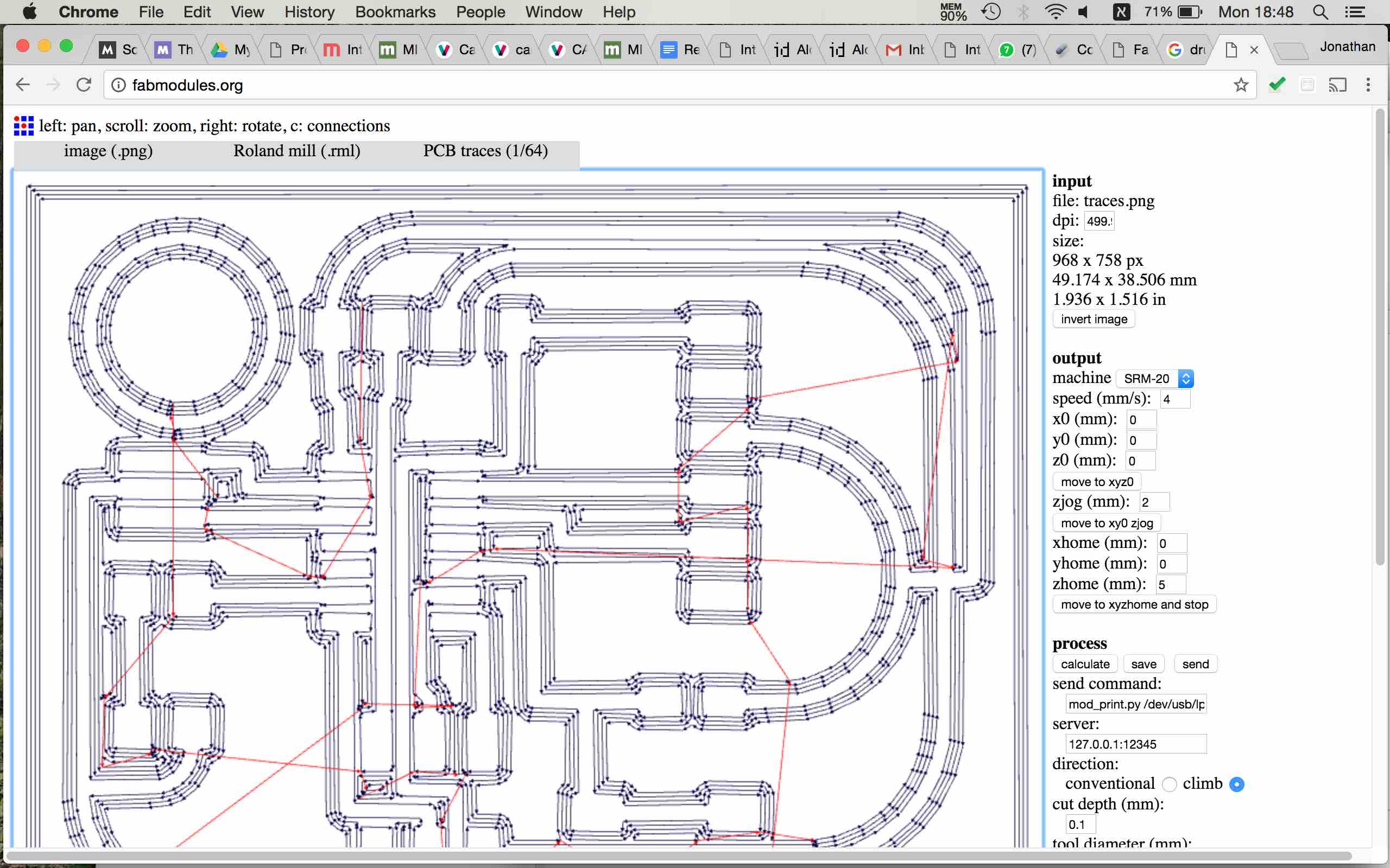
files was ready to mile so i uploaded to the school clound and sent them to mile.
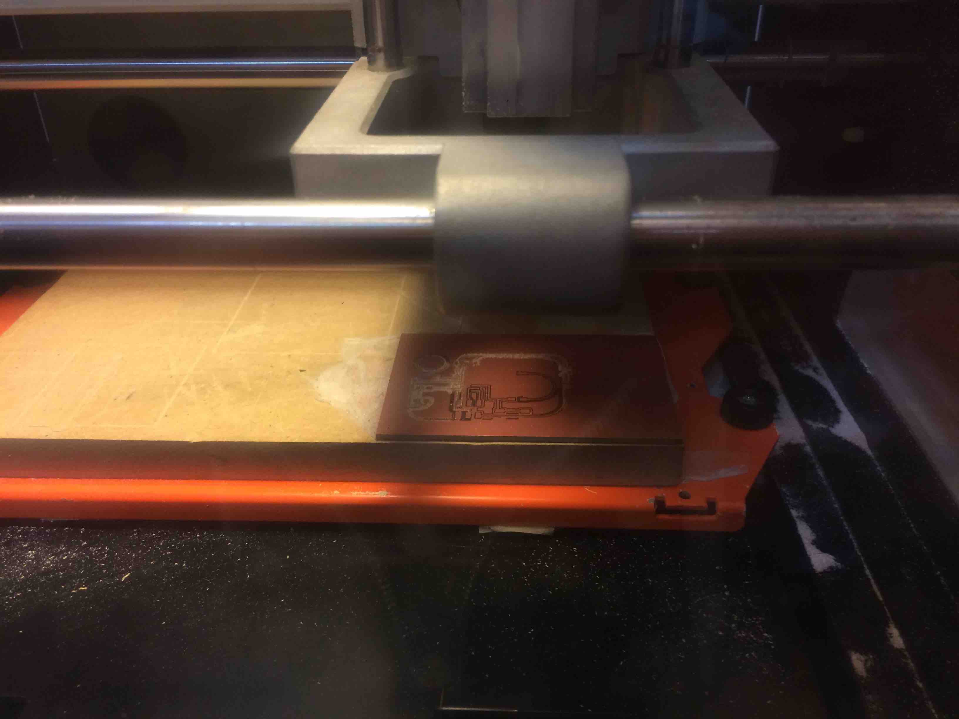
the base wasent 100% flat and for this reason there was some parte that milled well and some that the drill was bearly toching the surface. i needed to configurated the Z position 4 times and run it all over again until i got the board right.
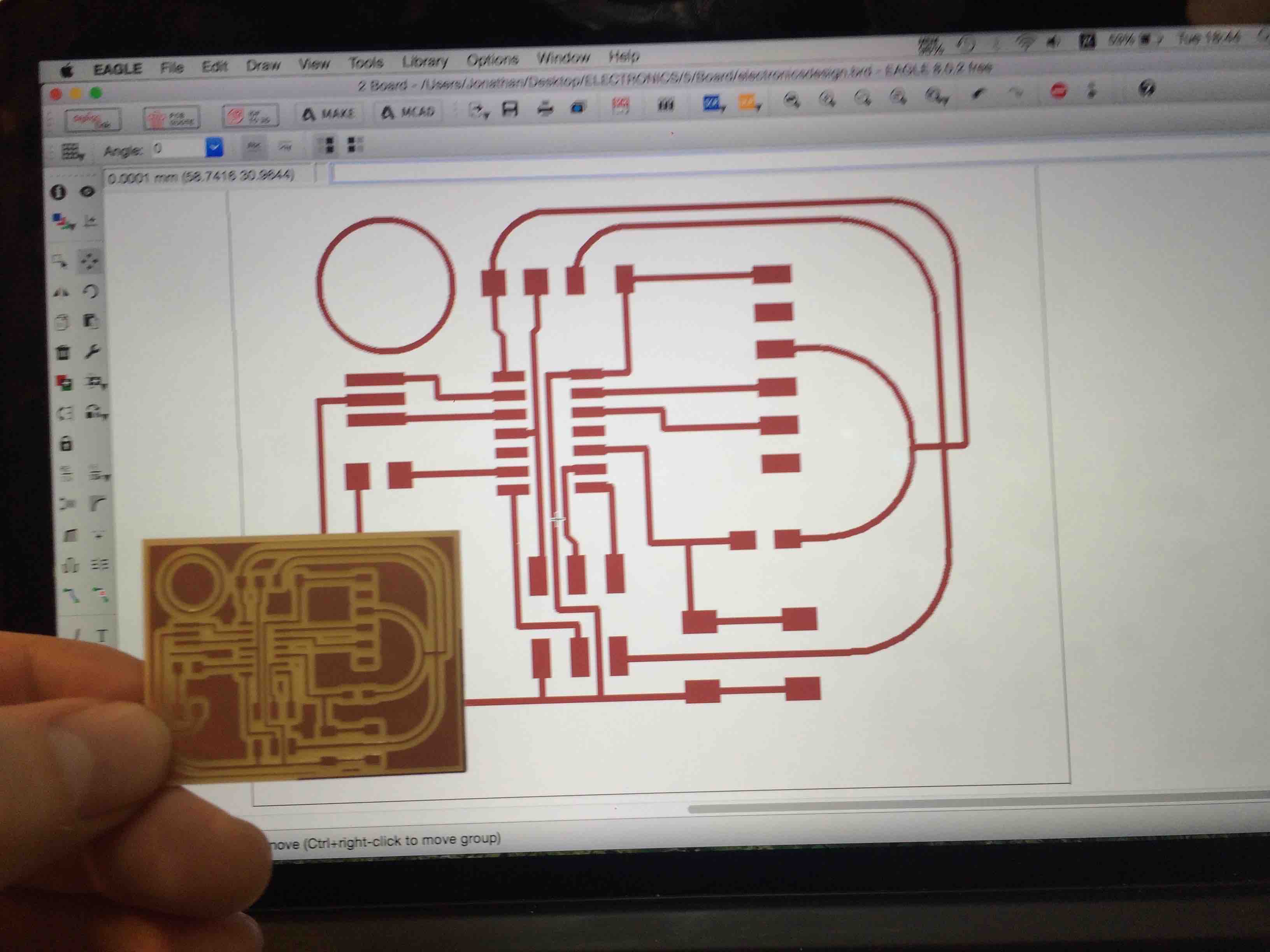
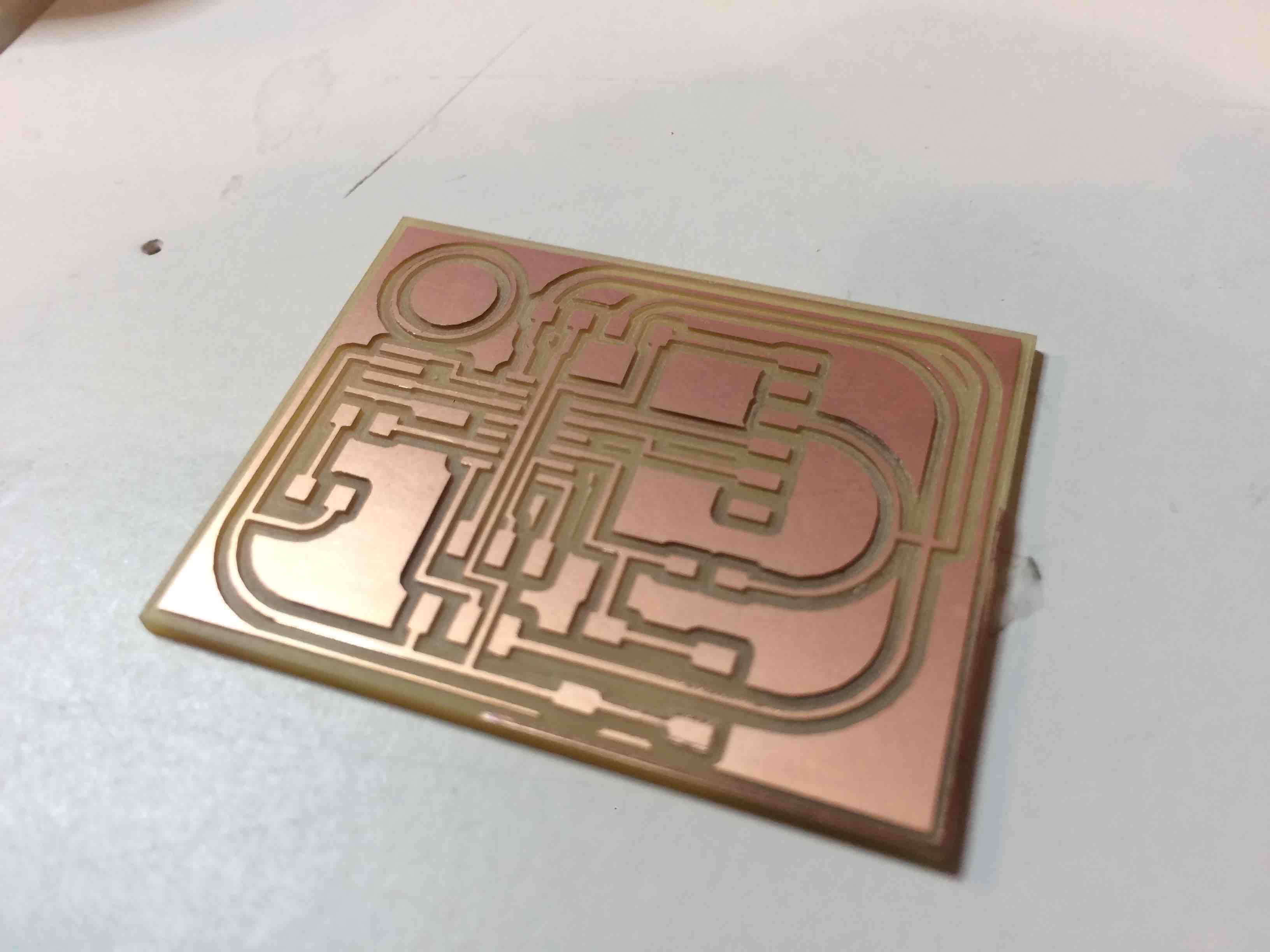
i was very satisfied from the result but i have to say that i could definitly make it much smaller as some of class mates made their boards half size then mine.
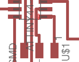
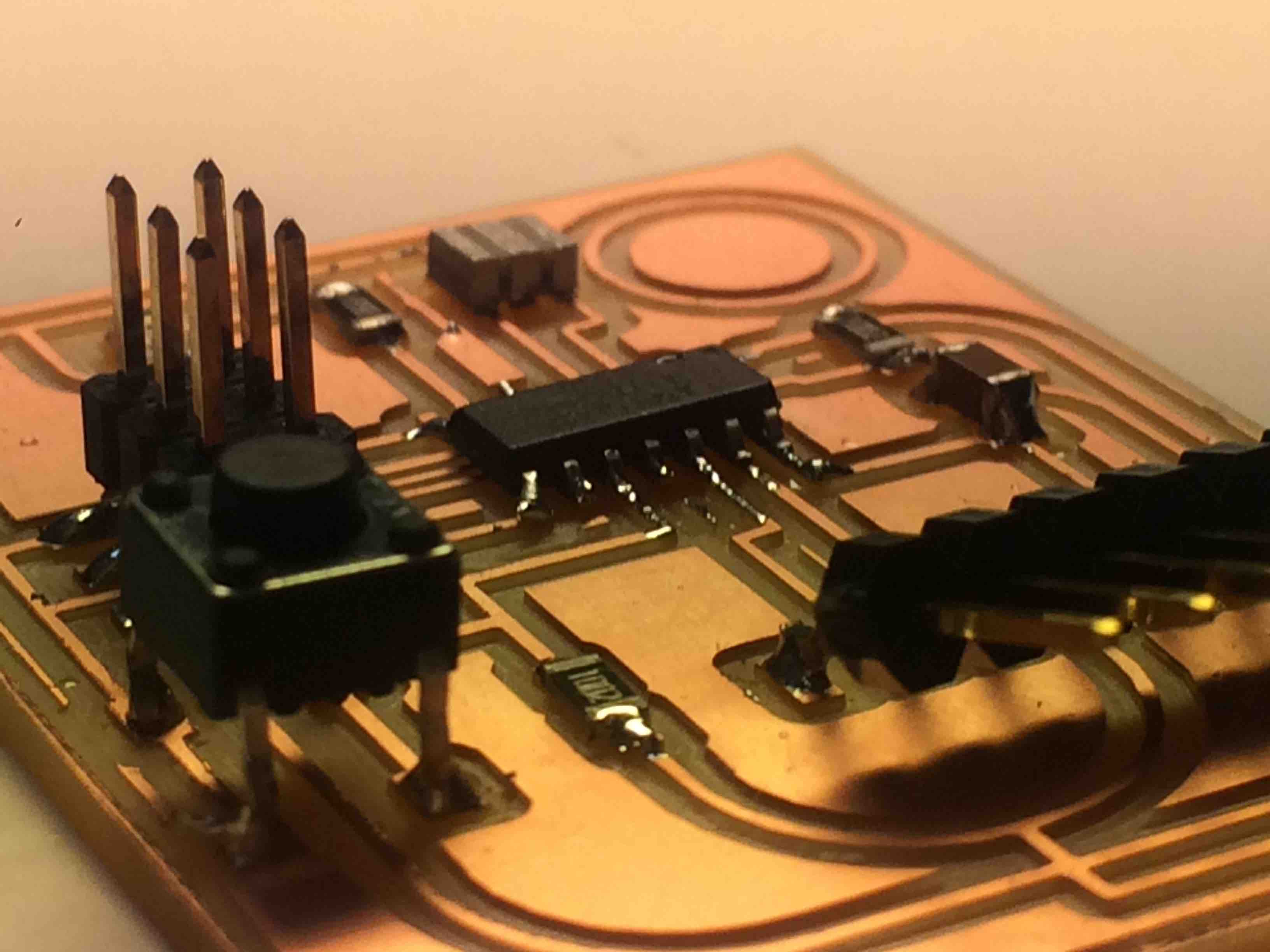
I started to soldaring the components to the board follwing the scheme i did in Eagle.
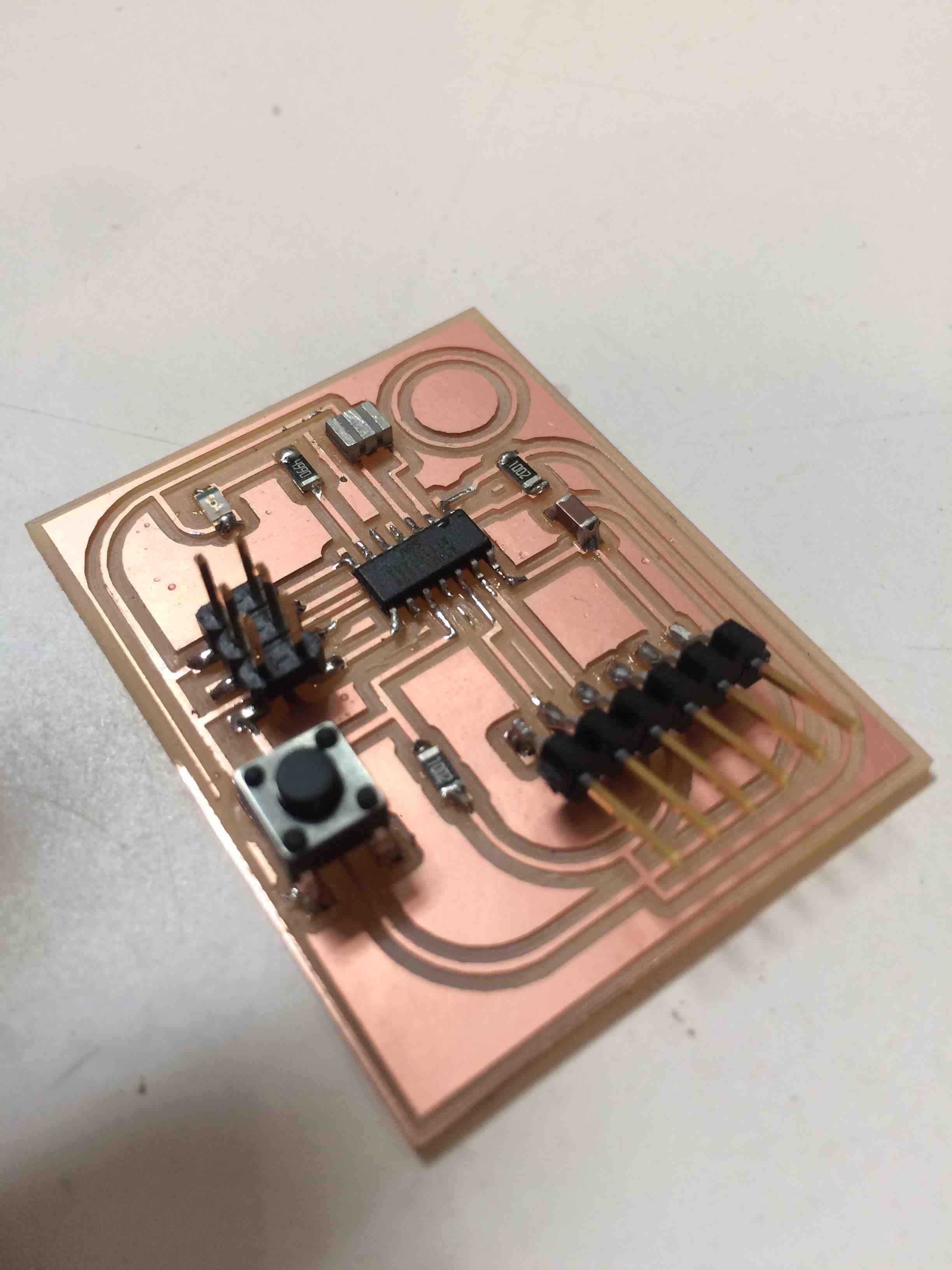
I didn´t have the time to check or programming the board yet, things i will do on the follwing week.