Explained how you parametrically designed your files for laser cutting.
Shown how you made your press-fit kit.
Included your design files and photos of your finished project.
Explained how you drew your files for Vinyl cutting.
Shown how you made your vinyl project.
Included your design files and photos of your finished project.
This week started with Neil's lecture on the potential of computer controlled cutting. He basically introduced to us the vinyl cutting and the laser cutting machines. I have always thought that vinyl cutting was only used for decorating computers and walls but, apparently, there is a lot more you can do with a vinyl cutter. It sounds dumb but it has never occurred to me that it could also be used for paper. Considering this, it can be used for origami constructions and geometrical patterns art pieces. It can also be used for silk-screen printing which I think is really cool and I definitely intend to try. I found a tutorial video from HONFablab which explain very well the whole process.
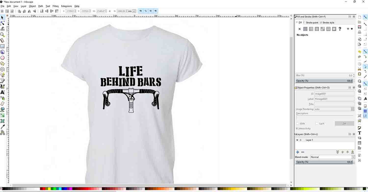
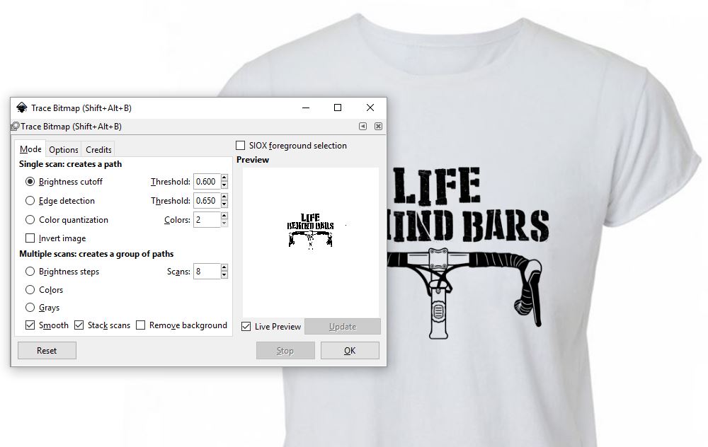
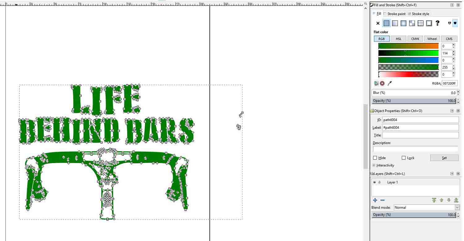
On Thursday, we had the Inkscape tutorial we couldn't do last week. I was very lost with the command shortcuts as I have some experience with illustrator software. I think is a very powerful software for being an open source program, but I didn't really feel comfortable with it. I guess it will be a matter of time and getting used to it. At first, we went through some of its important features, such as how to trace a bitmap from a jpg. This feature will be interesting for the vinyl cutting assignment.
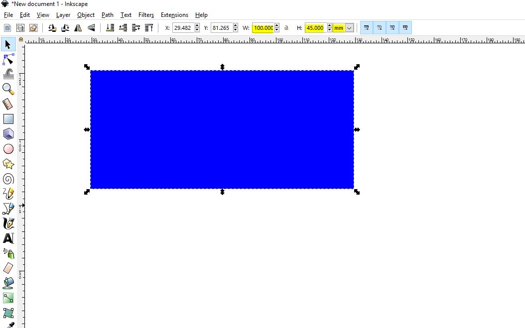
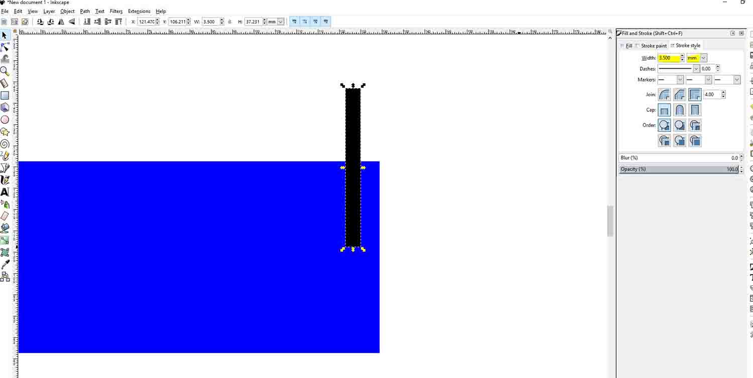
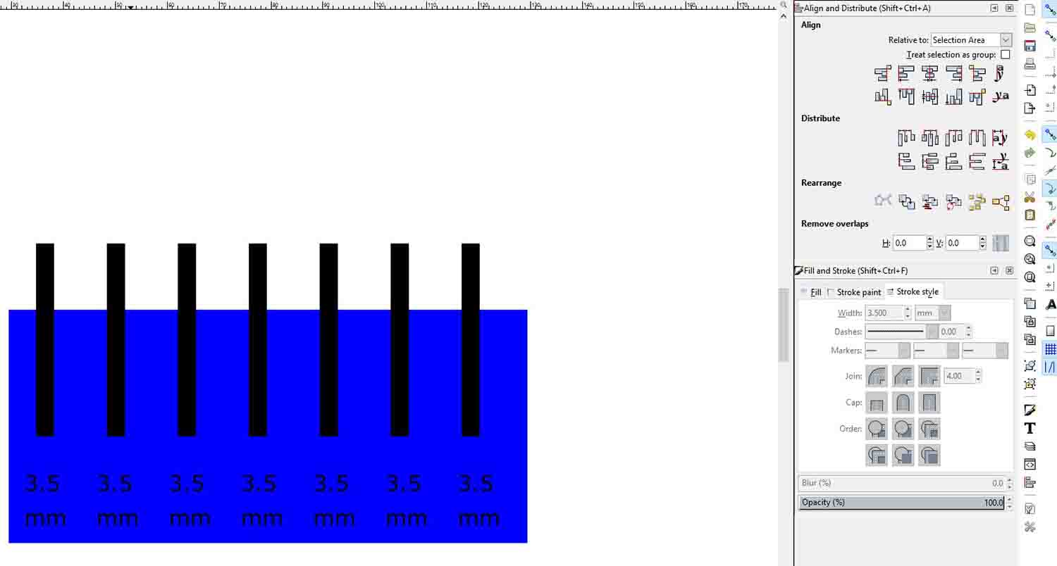
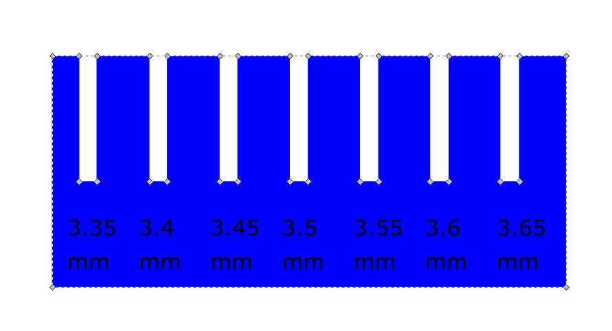
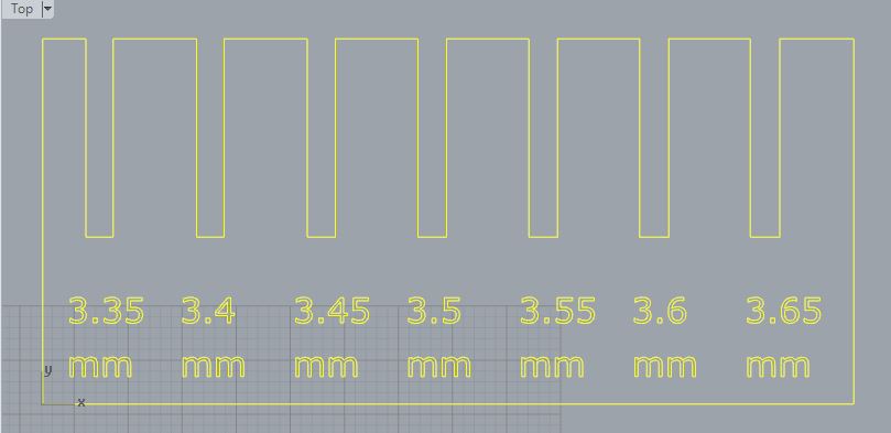
Afterwards, Santi explained us how we could use it for the group assignment to create a test template for the laser. First, we must give actual dimensions to the file. We will work on mm, to change this setting, we go to FILE, DOCUMENT PROPERTIES. There we can change the units and the artboard size. Once we know we are working on mm, we draw a rectangle. On the top of the screen we have the description of the rectangle. In this case, we gave it a 100x45 mm dimension. Now we draw a straight line, and give it a stroke of 3.5 mm (We want to do the test with 3.5 mm cardboard). Now we copy the line a few times. To align the lines evenly, Inkscape has an Align & Distribute Oblects tool, that is very handy. Afterwards, we are going to add some text with the description of each slot. We align them with the lines we have made. Now we only need to change the stroke of the lines and update the number on the text individually for each one. This is something that would be much easier with a parametric tool, but Inkscape is not parametric so we have to change it manually on each line and text. Now we only must do a subtraction Boolean and export to Rhino. We must export to Rhino because our laser machines' software is Rhino based. Before doing the Boolean, we must transform the lines into paths, it wouldn’t work otherwise. Also, we must transform the number to paths if we want Rhino to recognize them.
Once we have the geometry we save it and send it to the computer controlling the laser. And after updating the settings we can send it to the laser. Our laser works with colors. We must change the color depending on the order we want the laser to do the cut. We wanted the numbers to be engraved and the rest to be cut so we only needed two colors. It is always easier to work with absolut colors. We used red and blue. After the colors are set, the important step is to set the speed and power the machine will use for each of them. This might get a couple tries to get it right. Here, we recorded a video as our mentor was teaching how to use the machine. We experienced the catching on fire Neil talked about on Monday. Apparently it is not unusual and that is why you have to be watching while the machine is doing something.
.JPG)
.JPG)
Once we manage the right machine to cut our material we end up with a useful test piece to set our files.For this specific machine we used 12 for speed and 90 fos power on cutting.
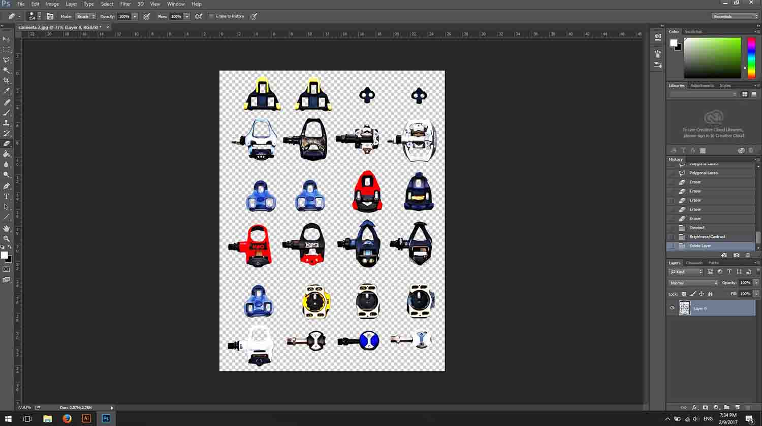
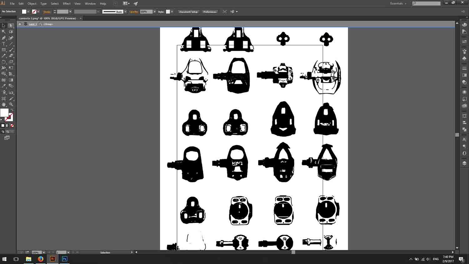
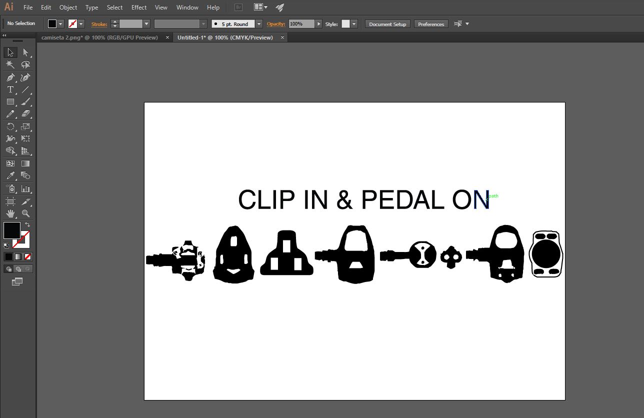
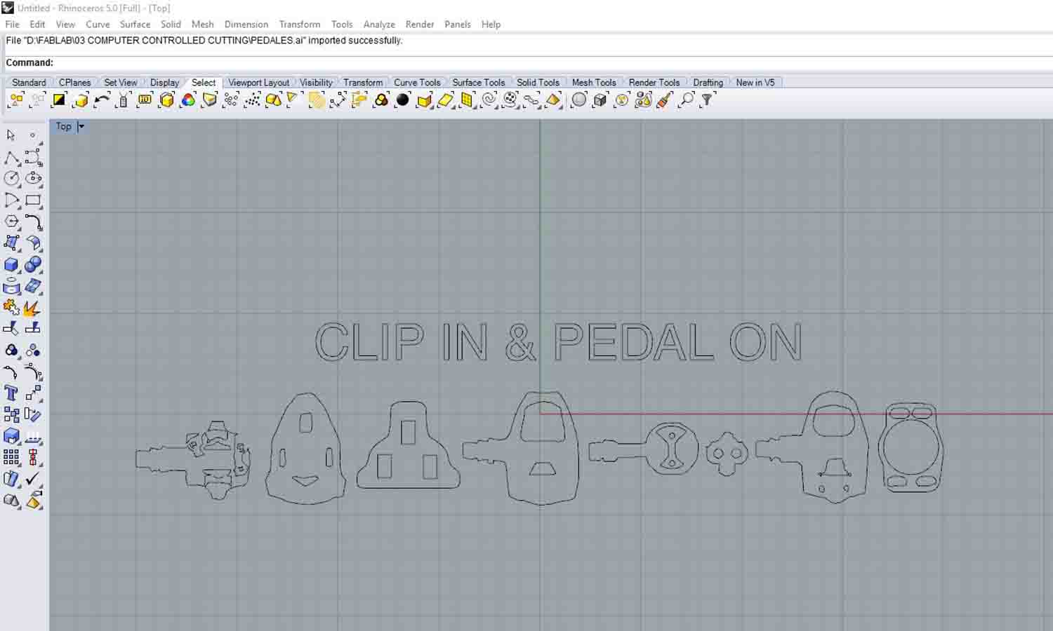
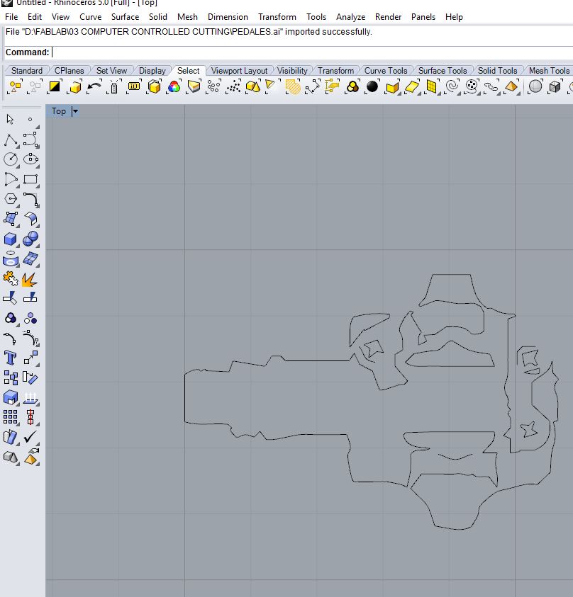
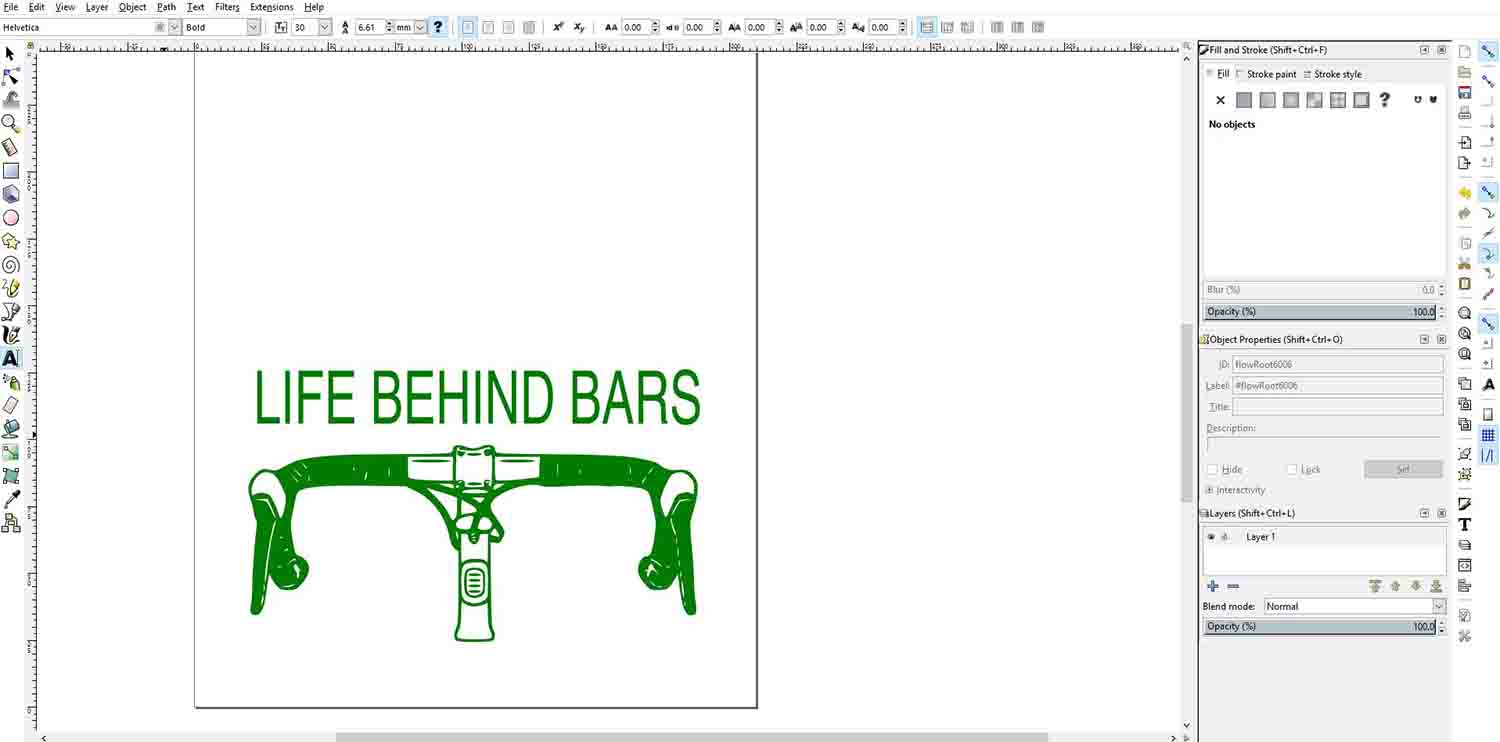
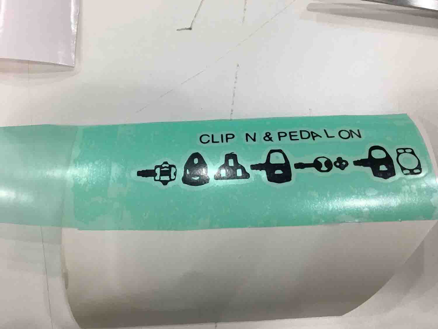
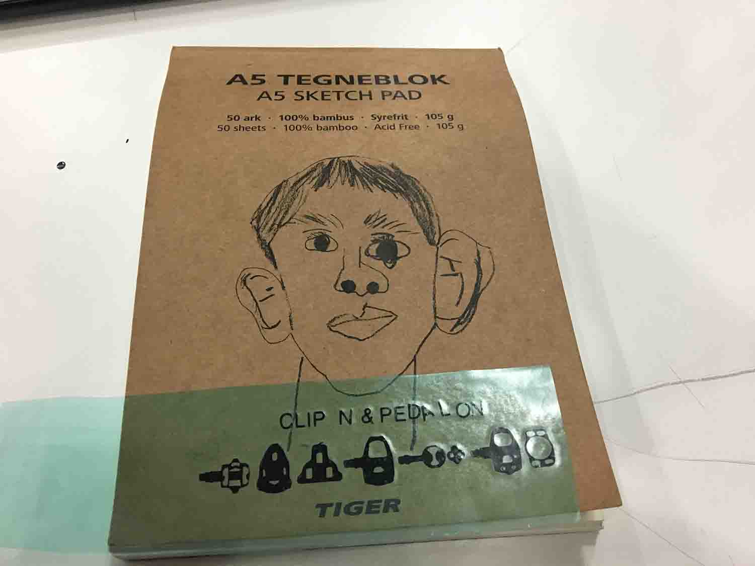
For the vinyl cutting assignment I wanted to do a sticker of something related with my final project. As I am doing a device for the bicycle I thought it could be fun to design a layout with the different kind of pedals and cleats. I thought it could be both used for a sticker and maybe if there is enough time for the sylk-screen. I first found a picture of the different pedals that exists on the internet. I wanted to trace it on Illustrator (as I am still faster and more comfortable than with Inkscape), so I first did a couple adjustments to the jpg on photoshop. I took the background off and adjust the contrast and brightness of the image. This is not a necessary step, but it will make it easier for the vector program to do the bitmap and it will give it more accuracy. When I had an OK image, I exported as png. I opened it on Illustrator and did the image tracing. I had to fix the lines and paths to get a simpler image that was right for a sticker. On illustrator you need to click on Extend for the paths and anchors to be shown. Afterwards I designed a layout with a few of the elements and add some text. I exported it to rhino, to check and fix some lines that I was sure where going to be weird.
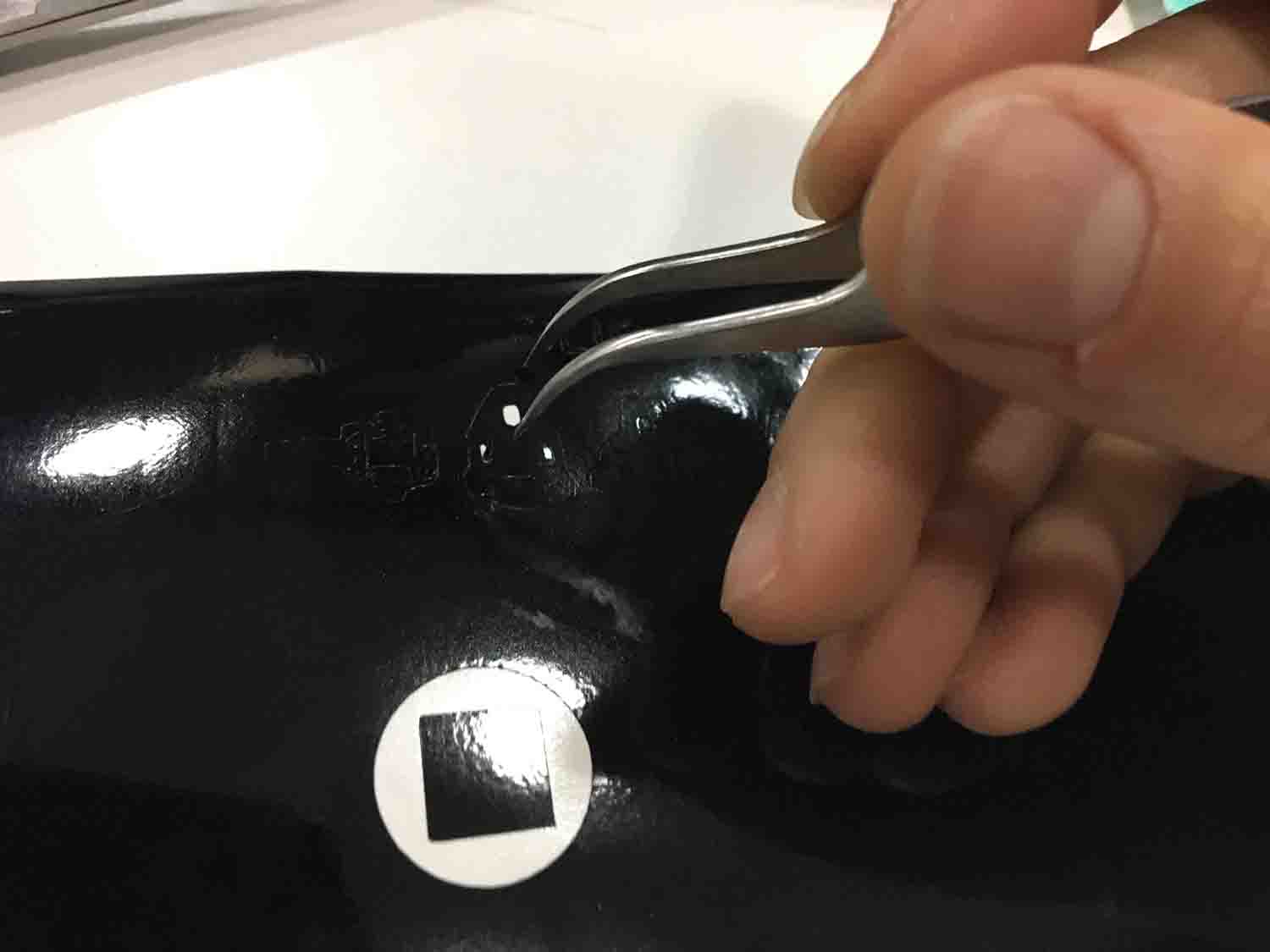
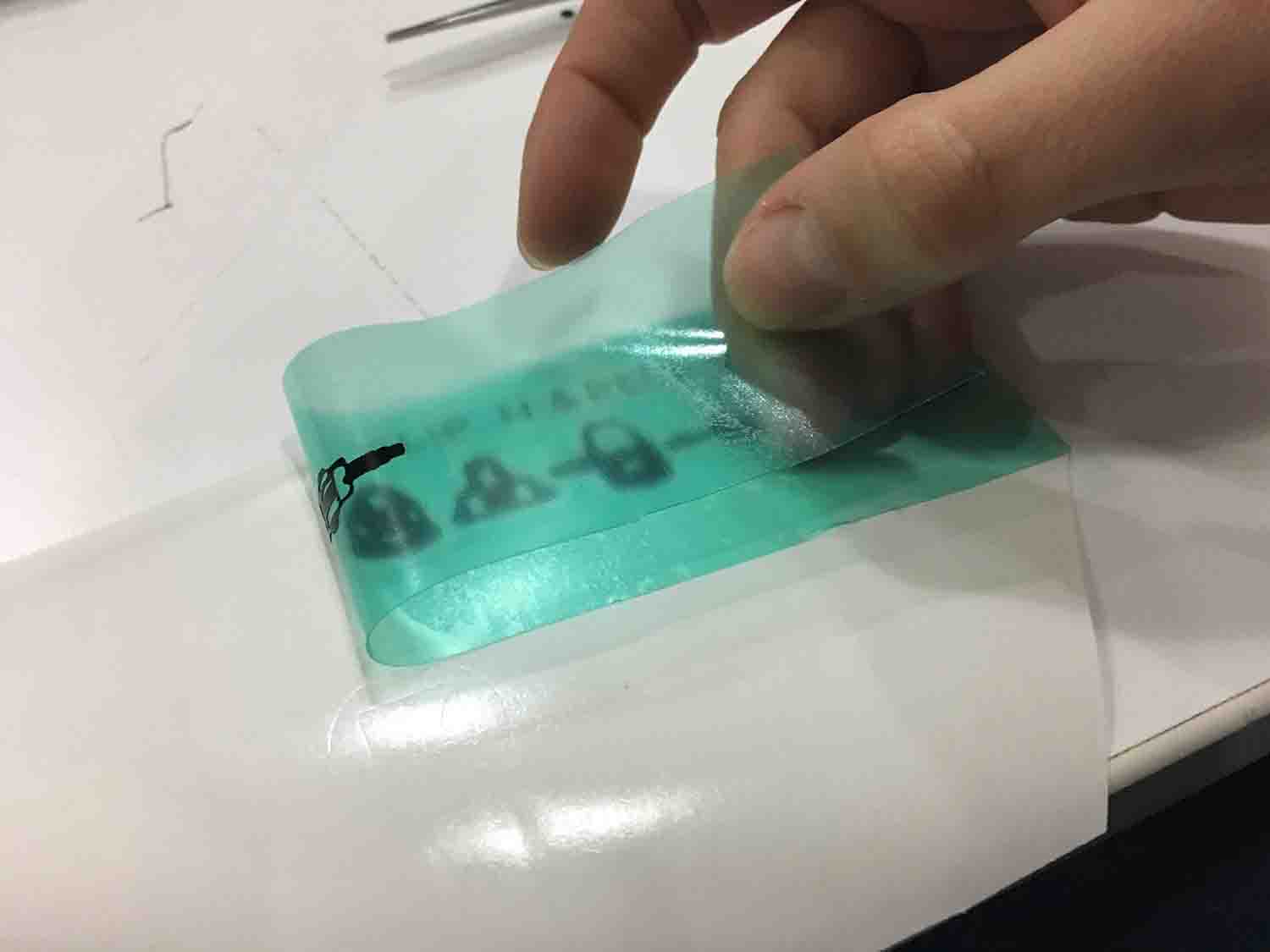
Once I got the file ready to go, it was time to move to the machine. First step is to choose a vinyl. The usually came in rolls, I choose a black one, but the machine accepts pieces too. This is very handy as scrap material can be used for small pieces. Once we have chosen the material we must do a couple test before cutting. The goal is to cut the vinyl part without cutting the paper that holds it together. The are 2 parameters for achieving this. The first one is how out the blade is. The second is the force of the machine. We can first do a test with the blade on our hand. Cutting through the vinyl, to approximately determine the length it need to be shown. Afterwards we put the blade on its location and run a machine test. It consists on drawing a square inside of a circle. If the settings are correct, the circle could be taken out without affecting the square. In this occasion worked fine. I didn't have to change any parameter. Once we have it correct, we use the machine software to open our file. It admits .ai documents and .eps. I have it on .ai format. First problem I encounter was that the software didn't recognize my file format. Apparently, it has to be an earlier version of Illustrator. I tried a couple and still didn’t work. Thanks god, Arnau told me to try with Illustrator 8. Apparently, it is the most recognizable illustrator format there is. Thankfully it worked! Once I have the file uploaded I just pressed cut. My second error of the day, I calculated wrong the scale and it was too small. This was a problem when I started peeling it. It was a tough one. Here you can see what a small scale it is. My notebook is A5 format which is approximately a Junior Legal American format. It gave me loads of trouble to peel it, as it can be seen with the letters. I didn’t manage to get them straight even though I used transfer paper.
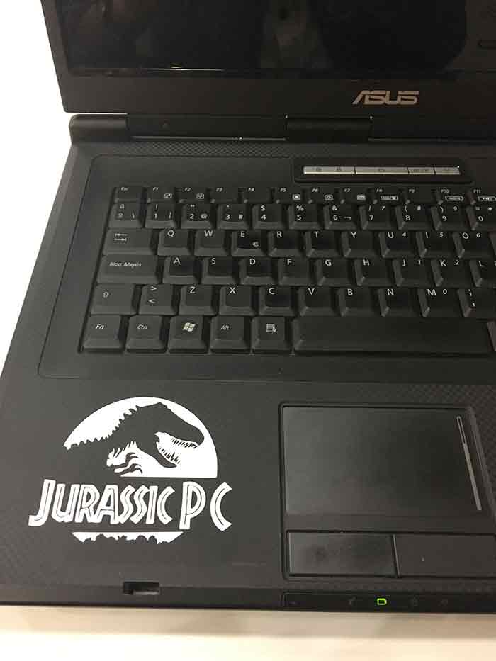
This week I also got help to install in an old computer Linux. I have never really used it and I am very interested on it. Esteban helped me through the process of installing and he made a little fun on how old my computer was, so we decided we shoud put a name on it with vinyl. I used the Jurasic Park logo a tweeked with illustrator to make it a little simpler and also serve my purposses. At the end I had a Jurassic PC that I cut in the vinyl cutter and was very neat on my old computer.
On Wednesday, right after Neil's lecture Santi gave as a class where he showed us different open source projects done with press fit joints. He also showed us a couple past years' projects. I fall completely in love with this cardboard surfboard project. As the assignment specifies it has to be a parametric model the one we build. I downloaded the files form the web-site, and the idea was to parametrize them with solid works, so the joints could be adapted to fit different materials. On Thursday, I realized it was going to be tons of work. Not only parametrize all the parts, but the assembly itself. I am a very stubborn person, so I didn't give up, but I decided to first do something else that meets the assignment requirements and afterwards try to do the surfboard.
I decided to do a lamp. I am really interested on lamp design. I found some very interesting ideas on Pinterest. I particularly liked this one as is press fit construction and is very parametrizable on both the number on elements and its size. I wanted to use grasshopper as I did last week's assignment on solid works and I want to regain some fluency on grasshopper. But time was an issue if I wanted to have enough days to do the surfboard and having a recent experience with solid works, that is the program I used.
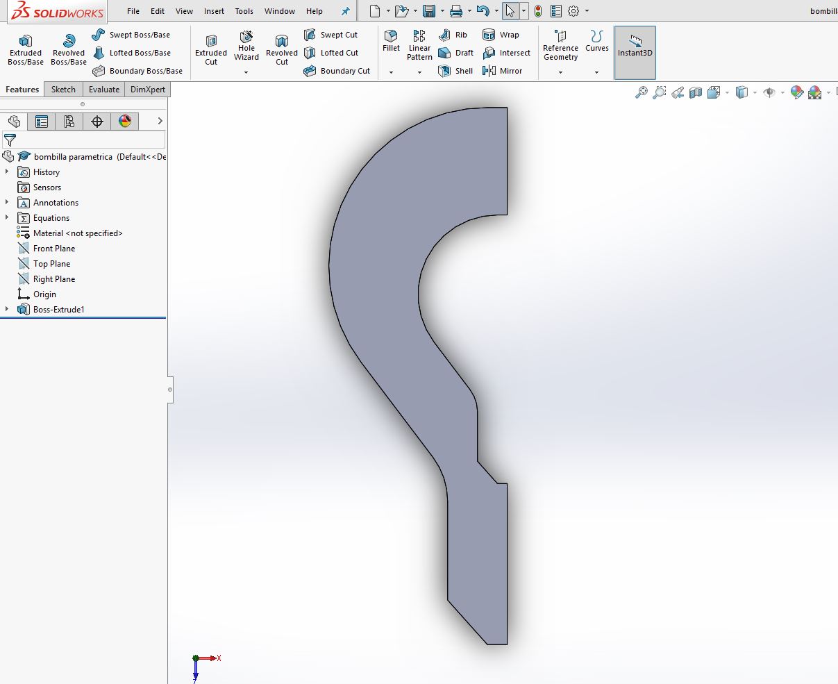
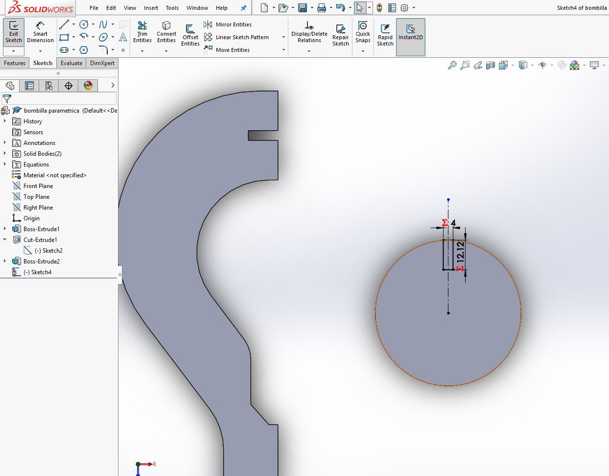
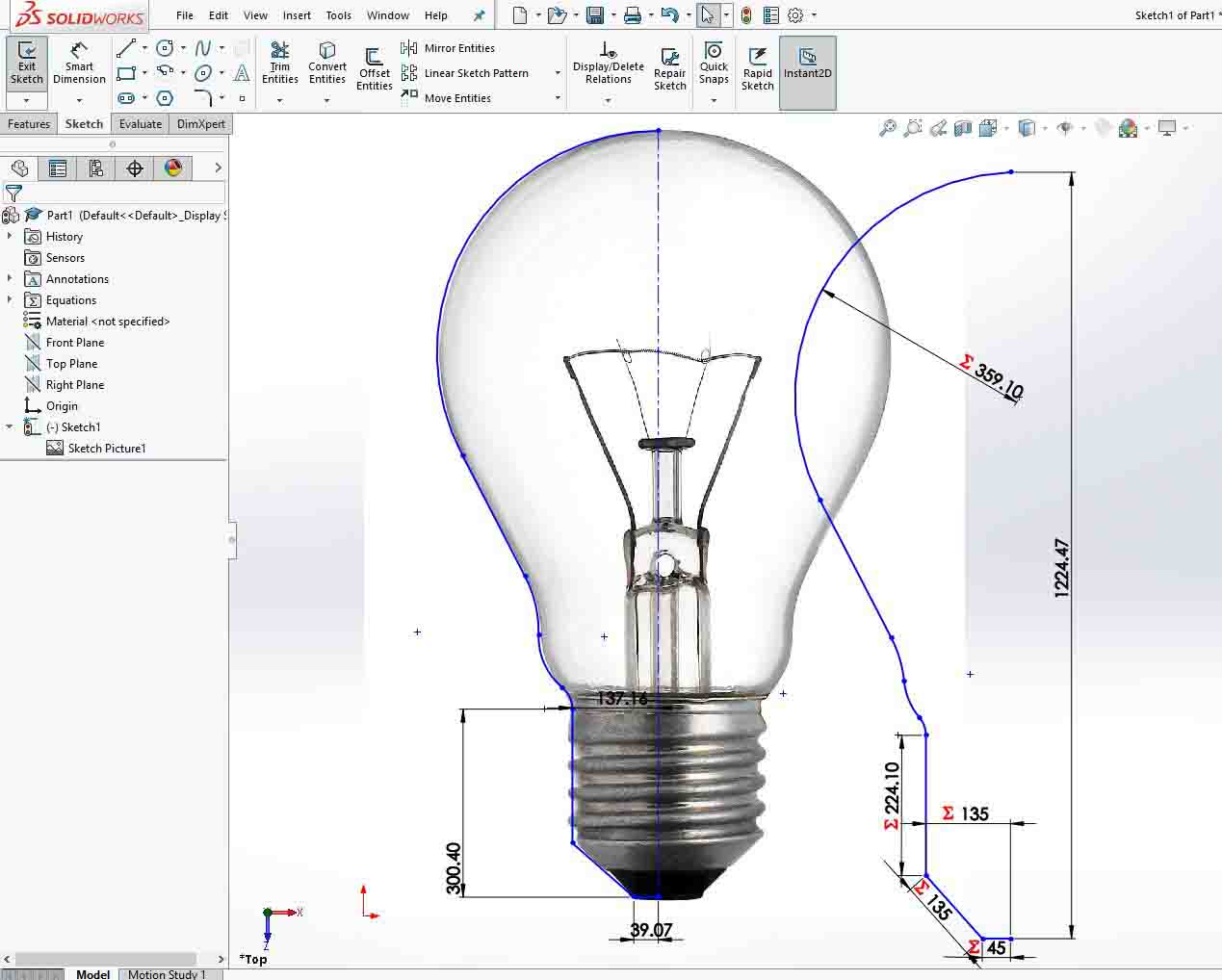
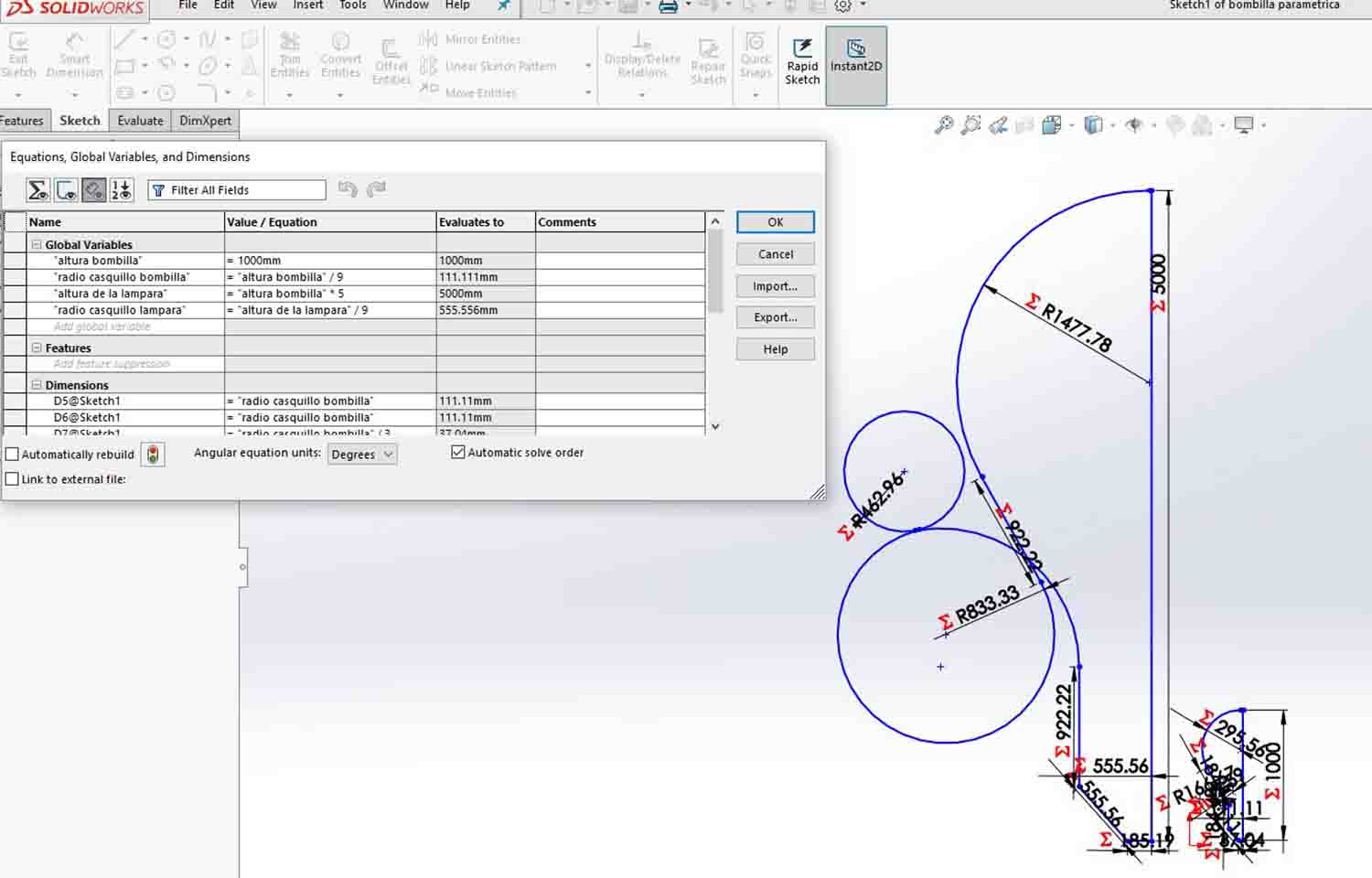
I started with the image of a bulb to trace its profile, as it will be the inside profile of the piece. After I had all the lines drawn I started adding parameters. I used global variables. To add these, you go to TOOL, ECUATIONS. I started with the bulb height and the radius of the bottom part. I mainly wanted to have a proportional profile. I didn't design it for different bulb models (After having built it I think it might have been a good idea to consider different inside profiles though). So as all I wanted was to keep the proportion between the dimensions when the height changed I added all the variables as relations to the height. Now that I am explaining it, it seems very easy but it took me awhile to figure them out. At the beginning, I had a lot of tangent curves, and it is very difficult to parametrize them right, so when the geometry grows, the curve does it good, instead of creating the other side of the tangent. This happened a couple of times, so I decided to simplify the geometry and end up figuring it out. The key is to instead of parametizing the radius of the curve, do it with the angle of the arc.
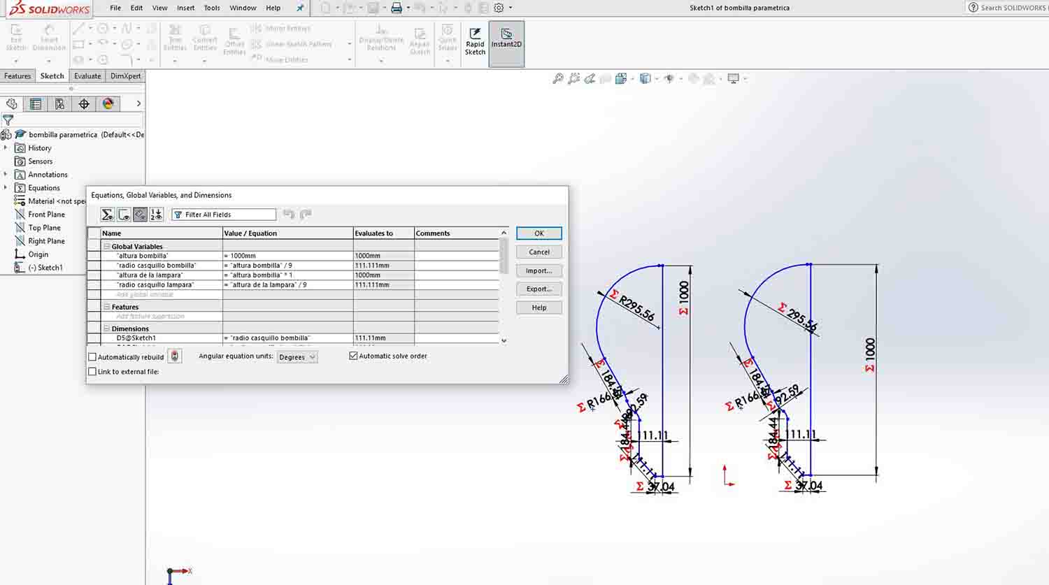
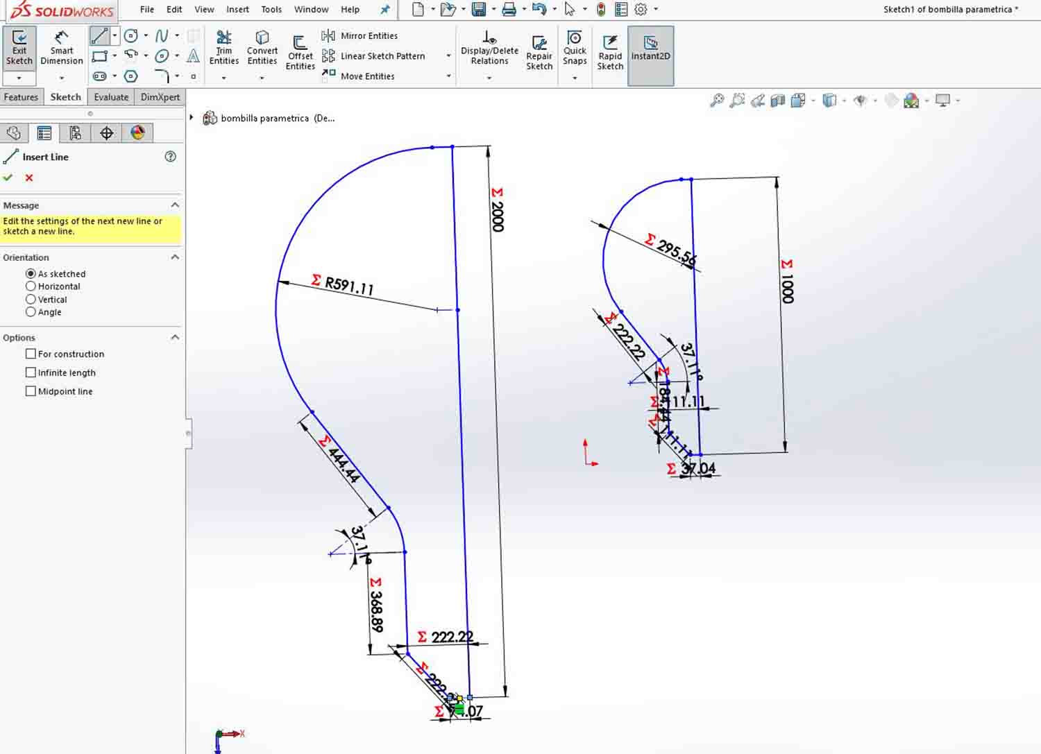
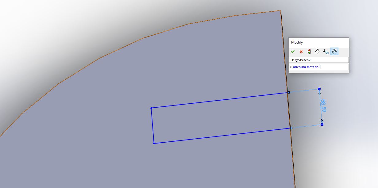
Afterwards, I copied the profile and changed the parameters to be related to the lamp height instead the bulb height. Once I had the right proportions and the increase of the height didn't destroy the profile I built the main piece. This is the one that will be repeat to form the lamp. The slots, where built with an extruded cut option. I parametrized the thickness of the material and these rectangles where made accordingly. The only step left was to build both anchors for the ribs. They were made with an extruded circle. To parametrize the number of ribs there will be is important to do polar array with the extruded cut geometry, instead of inside the sketch. It took me a while to figure this out and I had to ask my class mate Tomas for solving this problem. In my case I have used 5 ribs. Now that all the geometries are modelled is time to export the to .dxf format (Our laser software is Rhino based) and send it to the laser.
I had various problems with my file. First as is an exported geometry the lines where not closed. It is important to join them before sending the files to the laser. If the geometry was made with a non Cad software, sometimes is also useful to use MAKE 2D command. This will basically redraw all the curves with Rhino curves. It is specially usefull for Illustrator imported files, as sometimes Rhino might have trouble reading these. But after doing this and changing the layer color to red the machine was not recognizing my lines either. After going a little crazy I made it work. I created a new red color layer and set all the values of the layer properties to by layer. I put all my geometries on this new layer. I am still not very sure what value was the one giving problems but this solved the issue and the machine worked fine. As I was only cutting, not engraving, I set the values to 12 speed and 90 power.
.JPG)
.JPG)
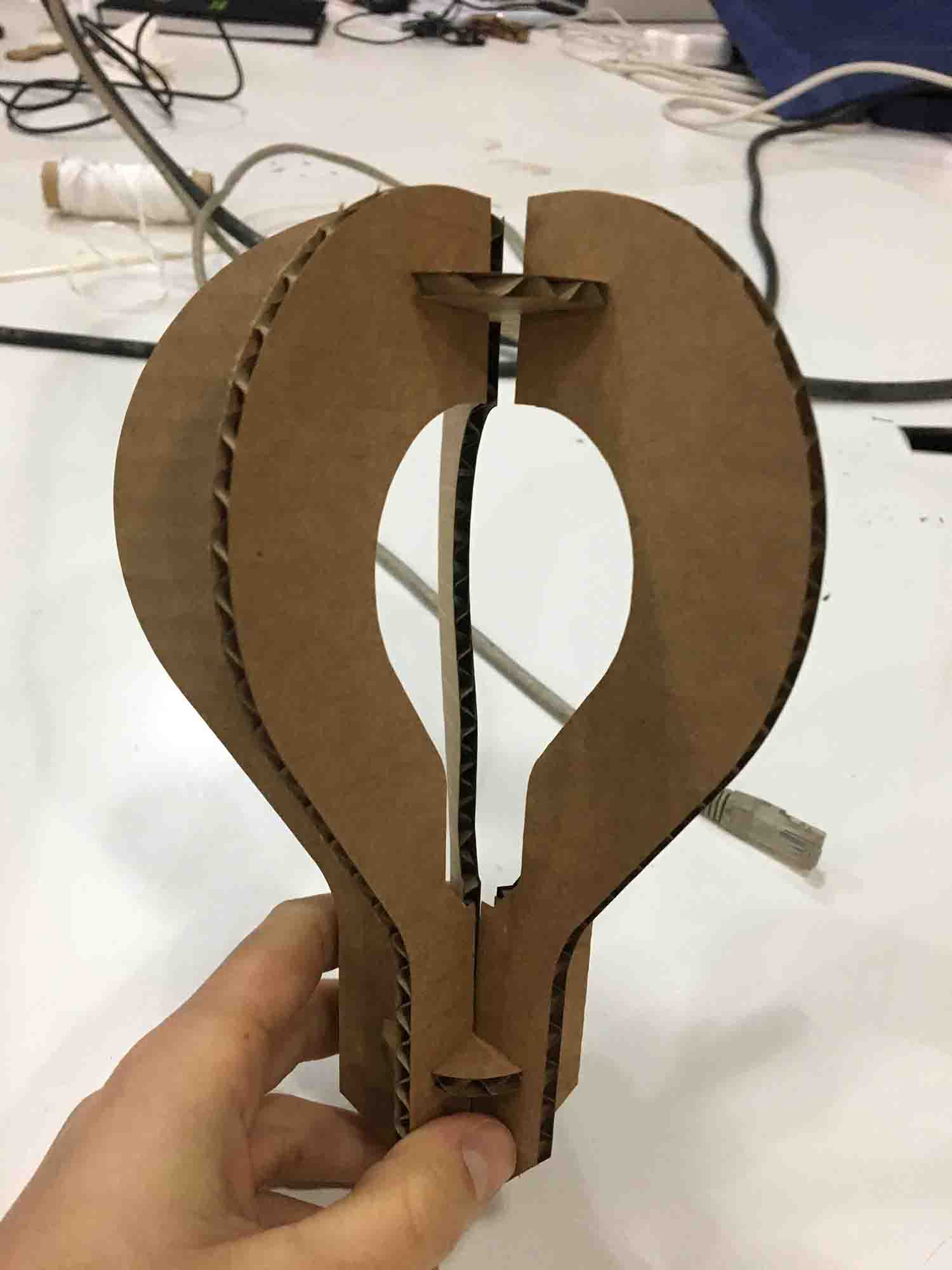
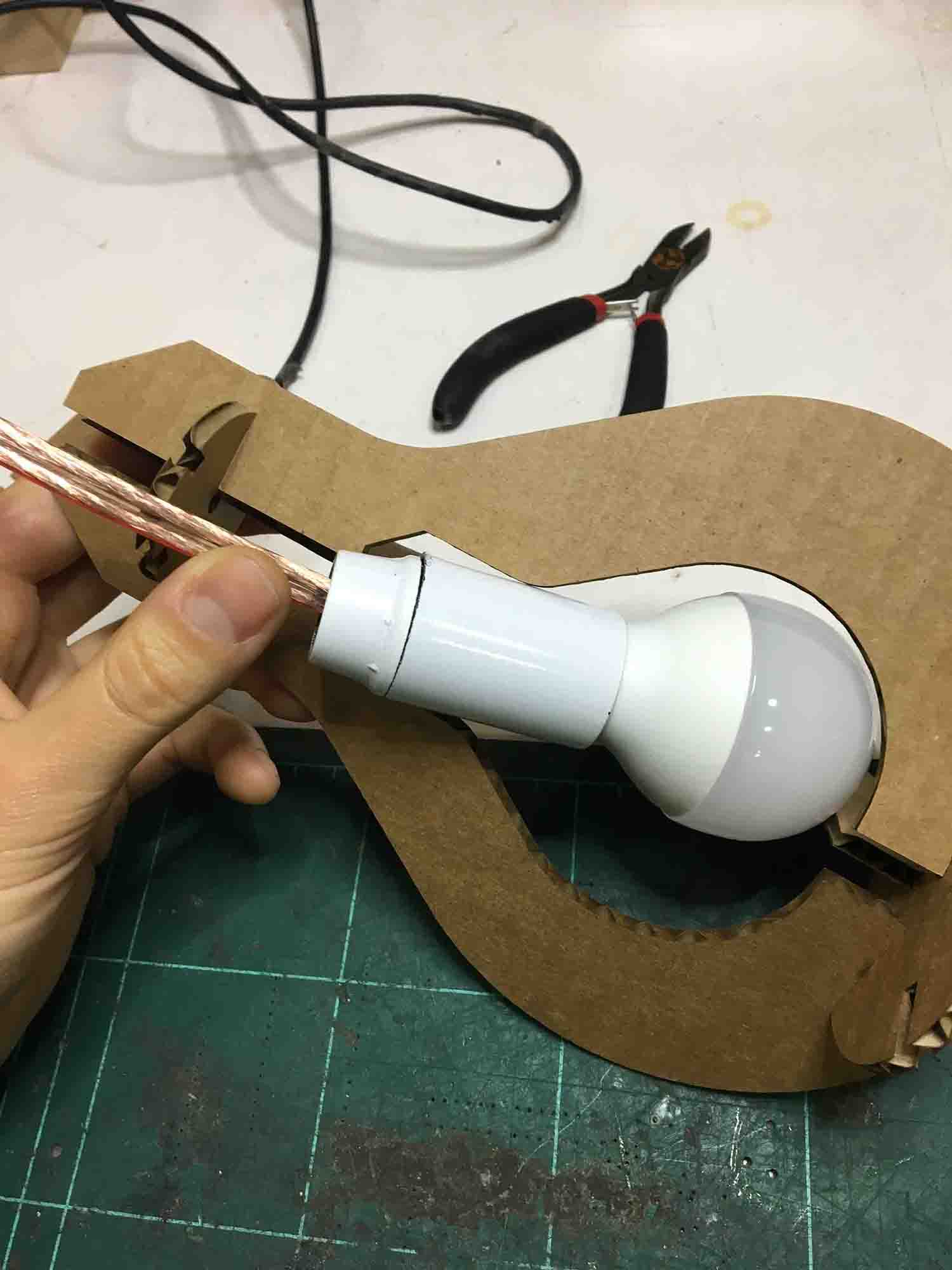
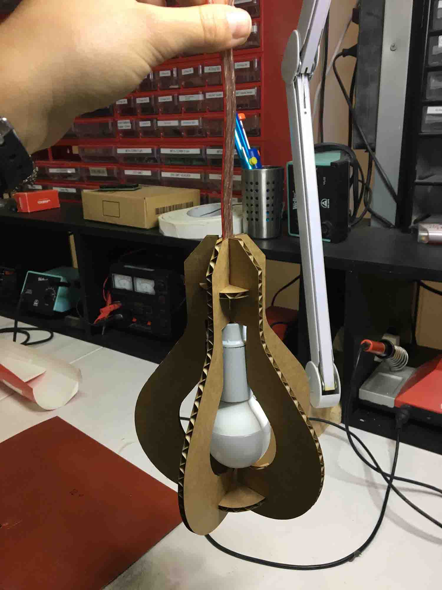
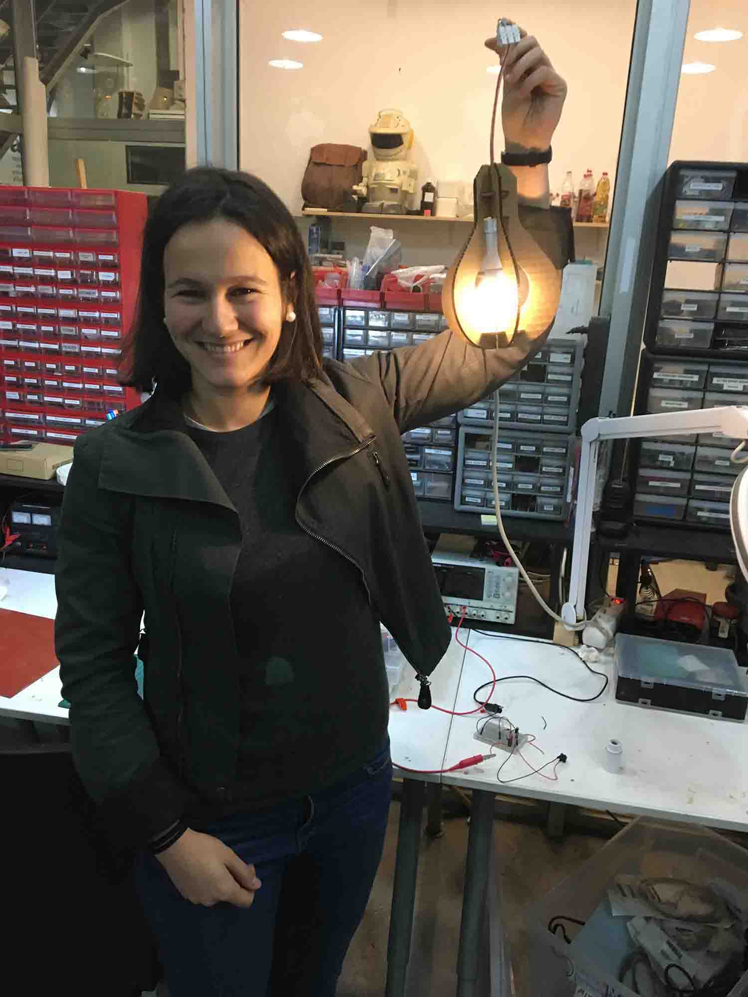
When all the pieces where cut, it was time to build my lamp structure. It was a perfect fitting as we did the test for this cardboard the day before with the group test. Also fitting cardboard is not very complicated and kerf is not really an issue. If fit is tight with cardboard you can push into place anyway for most of the joints. It is a bigger probles if the fit is loose. One of our tutors Santi found me a bulb and a lamp system and be built it to try it. I works great, but I will buy a nicer cable to fully build it. I also think that it will look better with a bigger size and more ribs. Having done a parametric design, this should not be a problem in the future!
I figured out that if I cut a surfboard I could use it for the composites assignment later during the course. I am not an assiduous surfer, so I don't have my own board. It is still a sport I enjoy a lot, but to be honest, the reason I am fully excited with this project is because I didn't realize the potential of fit press cardboard construction for solving actual problems until I saw this.
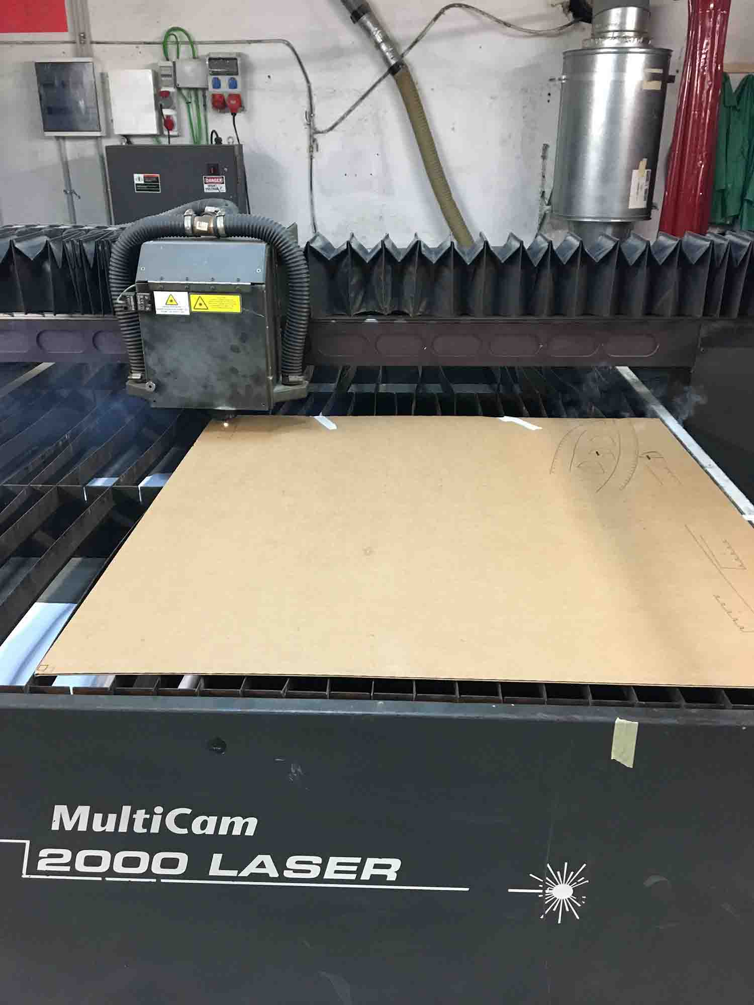
Fortunately, here at Fab Lab Barcelona, we have a huge laser cutter. This will make my life easier. We used 1x1 meter cardboard for the assignment so I had to fit all the parts on this measures. It was a though one, as I used this task to also understand the later building procedure and there were tons of parts.
Once I had all the pieces distributed on 5 pieces, it was time to go to the laser cutter. This machine has different settings as it is an industrial machine. It doesn't work with Rhino and it runs with a software that only reads dxf's. First, on the software, you just assign to each geometry a value (cut, engrave or raster). This can be assigned to layers as well, which makes the process much easier. The you send the file to the machine and all the adjustments of power, speed and air pressure are done with the machine own controller. It is a bit scary at first, but at the end it works similarly to the others. Once everything is set right to press play! This machine on top of speed and power also has a very useful setting called cut press. The machine has air pressure shot while the laser is cutting and this helps to increase the power of the machine. You can play with this set in order to cut at a faster speed. I have used SPEED 80 POWER 250 CUT PRESS 20 for cutting and SPEED 100 POWER 80 CUT PRESS 3 for engraving.
Once I had my first piece cutting everything seemed right, I must admit I was reusing one of my classmates' previous settings for the same material. So everything should be right.
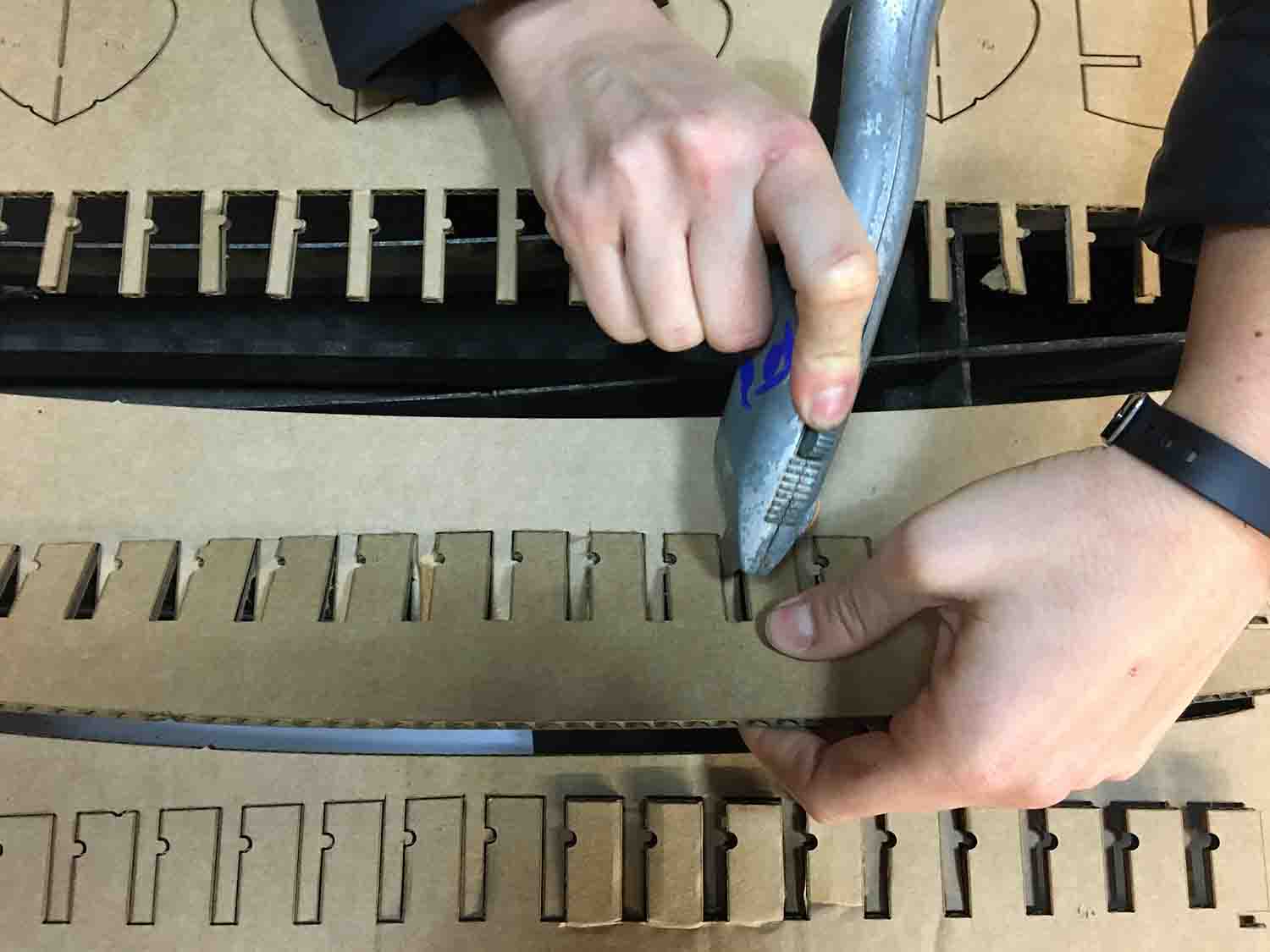
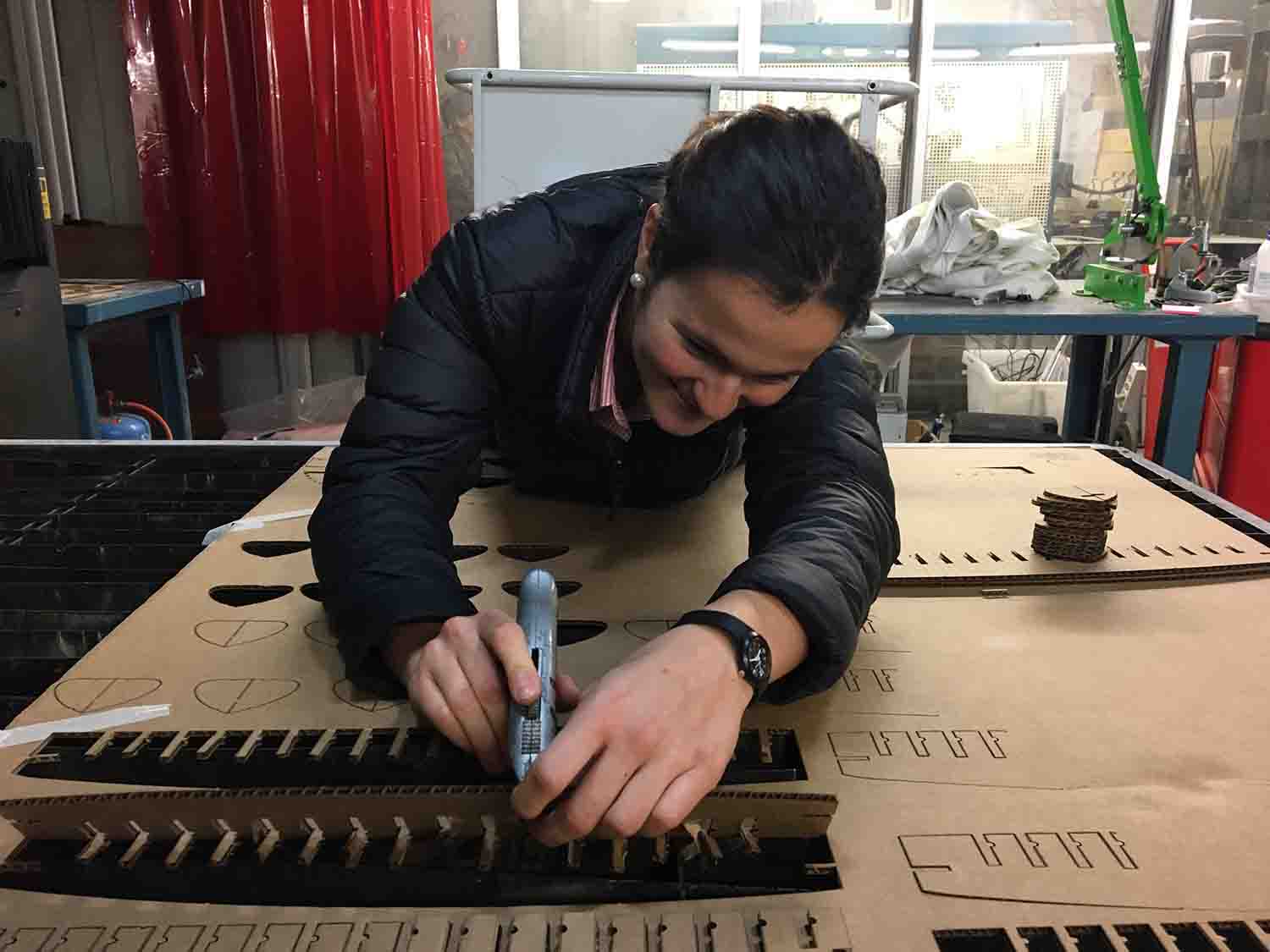
As this machine is bigger, the laser power is bigger too. So as a matter of security, it has a few sensors on the side that shut down the machine if anyone gets too close. It is a feature that is useful in terms of safety, but the sensors are too close to the computers that control the other laser machines and tend to get activated unintentionally. So, some minutes after the machine had started with my first board, one of my classmates shut the machine down by walking through the sensors. Unintentionally of course!! The problem is that the file and the setting get lost on the process. It was unfortunate, but to be honest when I started taking out the few pieces that were completely cut, I realized that the settings were not that great, and most of the pieces were not completely cut from the cardboard. I had to use a knife to separate them without damaging them. It was not only problem of the settings, it has to do with cutting bigger pieces of material. When you cut a board of 1mx1m the chances it is not completely flat are huge. With this lasers if this happends, the laser might not be properly focus and not get the cut totally right. I am pretty sure this is what happened.

I want to continue working on my surfboard as I think is a cool pressfit project that has an actual aplication on real world. I also have realised that it will be extended on time as I will have to do it while working on next week's assignments and before using so many material and machine time I will need to wait till all my classmates are done with their assignments. That is why I have create a new section of my webpage strictly dedicated to the process of the surfboard creation.
BACK HOME <<<