WEEK SIX
-Electronics design-
ASSIGMENT: The assigment for this week was 1. Redraw the Hello Hecho board. 2. Add (at least) a button and LED (with current-limiting resistor). 3. Check the design rules, make it, and test it. It is extra credit: to simulate its operation and also is extra credit: measure its operation
1. Redraw the Hello Hecho board.
First we had a class by Emma Paresci, our instructor. She explained us the basic of the electronics. First with the icons and terms and also an explanation about the program that we have used to design our board, Eagle.
Personally I have never did electonics and this week was very hard to follow and understand. I am comming from design background so it was completely out of my comfort zone.
0. Before to start we watch two tutorials in youtube aboue Eagle so we could understand better the program.
1. First I download Eagle, the program to redesign the board.
2. You open Eagle and create a NEW PROJECT.And you put it a name.
3. You right click on this project and you create a new squematic.
The squematic is where we will define which components we want to have in our board and with what do we want to conect those components.
4. In the main window of Eagle, the first window, you need to go to libraries and diselect all of them . And then you have to select the right one which is, FAB. There is where you will find all the ocmponents that you need.
5. You close the library window and you go to the project and inside the squematic. You will see a white window like this one and to start putting the components you have to type ADD in the top bar.
6.Once you click ADD it will open a window with a lot of libraries. You will the FAB library. There is where you will find all the components that you need.
7. Once you have found all the components you need you have to connect them in order to later program it.
8. To do so, conect the ocmponents, you have to use the icon that says NET and draw like a wire line.
9. Once you have it you need to determinate with what do you want to connect it. To do so you mst click NAME in the tp bar and you will have to type the components that you want to connect it with. An example would be: VCC.
10. To understand better what are we doing and what components are we working with we can use the icon of LABEL or TEXT to just write what we are doing.I did so naming all the extensions that I connect in order to later remember what is what.
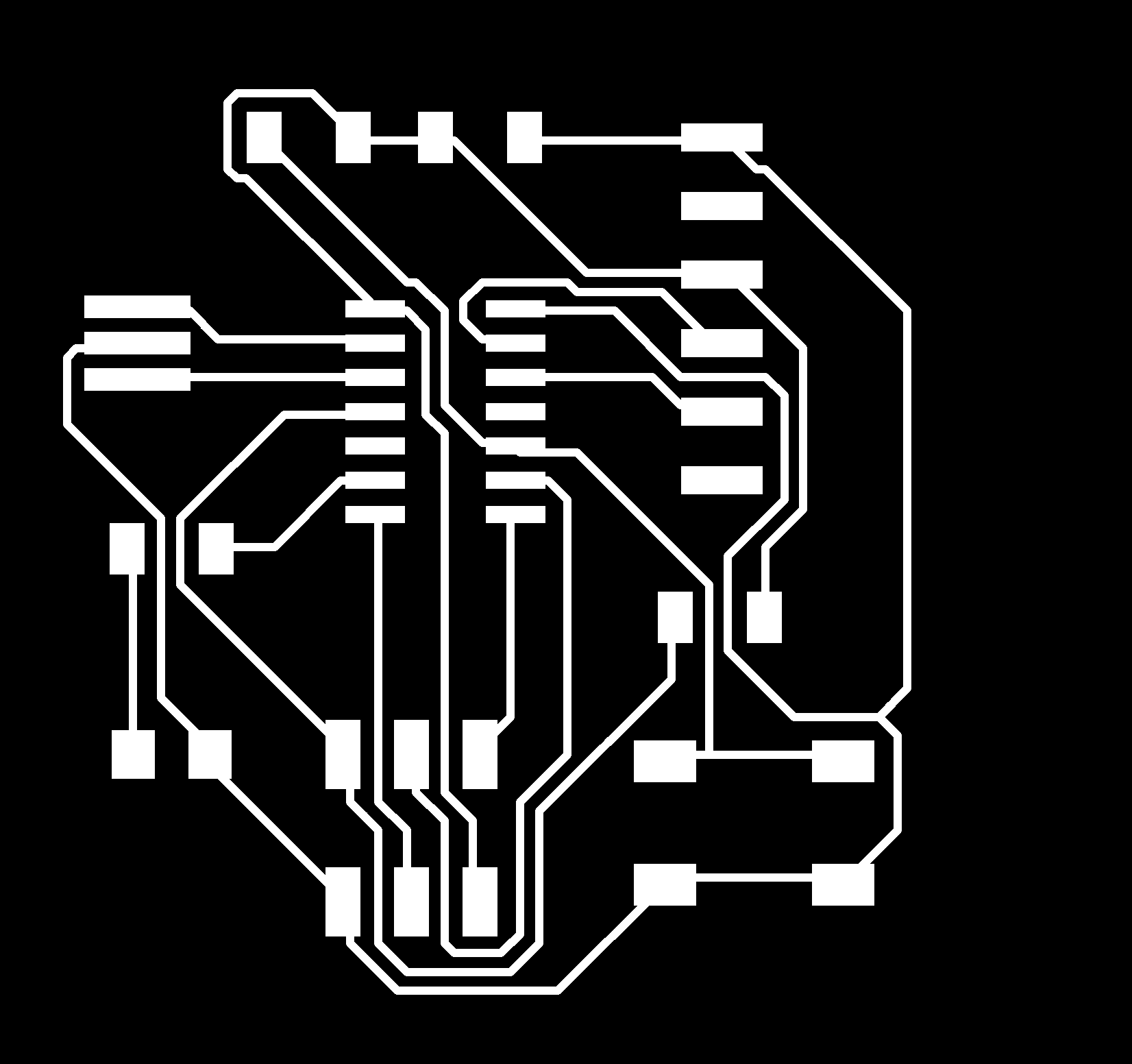
Squematic done! Lets see how it looks in the board.
11. The next step is to go to the icon that says BOARD and once we are there it will open a window like this. Here is where you will define the shape of the traces and distances between your components. You have to be careful and try to do it in a way that they are 100% connected.
12. There is a nice option that is the one I have used that is going to TOOLS and do AUTOROUTER. You have to select the once that says 100% which means that the traces are perfectly connected. If not you could have problems later.
After this we need to make sure that the thicknes of the traces and spece between them are the correct ones. To edit so we neeed to go to DRC icon and put 0.04mm everywhere.
13.You have to resize the white line frame and place it around the board. And also you can disable other layers in order to see clear the design traces.
14. To make sure that the traces are going to respect the others we edit the distance between them and also the thickness. To do so you have to go to OPTIOS-DEFAULT-CLEARANCE-And I put 8mm everywhere.">
Let's create the PNG files to start milling!
Now that everything is done we have to crate two PNG black and white files.To do so:
1. First we select the grid in order to see better and then we draw a RECTANGLE around the area we want to cut. You have to have selected the TOP view and the rest NOT SELECTED.
2. Then we go to FILE- EXPORT- IMAGE.
3. It has to be 1000dp as a quality and monocrome.
4. And then we need to do the same with the outer line that we will cut. But to do this one we need to select the DIMENSION layer and the rest NOT SELECTED.
1. First we prepare the machine and the bed before to start.
2. We introduce the right end mill.
3.We open the PNG file, first the traces one. And the same as last time. We SELECT FILE-VIEW- MILL TRACES-CALCULATE- X,Y POINTS- OPEN CONNECTION WITH THE SERVER- CALCULATE AGAIN- MOVE TO ORIGIN-SEND FILE.
4. We close the machine for the noise while is milling.
5.We check that the traces are done correctly.
6.We changle the end mill for the deeper and thiner one to cut the next file the is the outline.
7.We close again the machine for the sound.
8.We remove our board and we clean it with water and soap before soldering it.
9.We sold our board with the right components.
And with the right tools
10. Here is the resoult.
11.Once the soldering it is done we need to cheeck with the multimiter if there is any short and if it beeps when it should beep. Thanks god my board beep when it was need it!
12. To see if my computer can read the microcontroler I took the programmer and with a cable I connected wit it. And then I connect the programmer in the computer.
13. Once I connect the programmer I open the GIT BASH and in order to detect both things I had to type the following: avrdude -c usbtiny t44
14. And in my case it detect both devices, the programmer and the new microcontroler.
Programing the led with Arduino ATtiny 44
1. First I have open Arduino and I have downloaded the ATtiny in Arduino.
2. Then I have stablished the clock in order to be in the same time with the microcontroller. To do so I have gone to TOOLS- clock- EXTERMAL 20HMB, which is the same as the programmer.
3. FILE- EXAMPLES- BASICS-BLINK.
fINALLY i HAVE REPLACE THE led FOR THE NUMBER OF THE PIN i HAVE CONNECTED THE LED, 7.
TROUBLES AND FRUSTRATIONS
As I said at the begining this is so far from my comfort zone and I found it so difficult the assigment of this week. I come from a deisgn background so everything is new for me.
1. Interact with Eagle was a bit tricky, the squematic part.
1.1 First I get confused with some libraries.
1.2 I spend so many time trying to find the write components.
1.3 I get so frustrated when the squematic because I was not picking the right icon. Insted of connecting the components saying NAME in the top bar I was just typing names.
2. Interact with Eagle was a bit tricky, the board part.
2.1 When picking and moving the components was a bit anoying as you have to pick the elements from the middle cross. But at the end I have got it.
2.2 Creating the png file at the begining I missed the square around my board so I the background was too big.
Files