
〈
〉

Apoorv Vats |
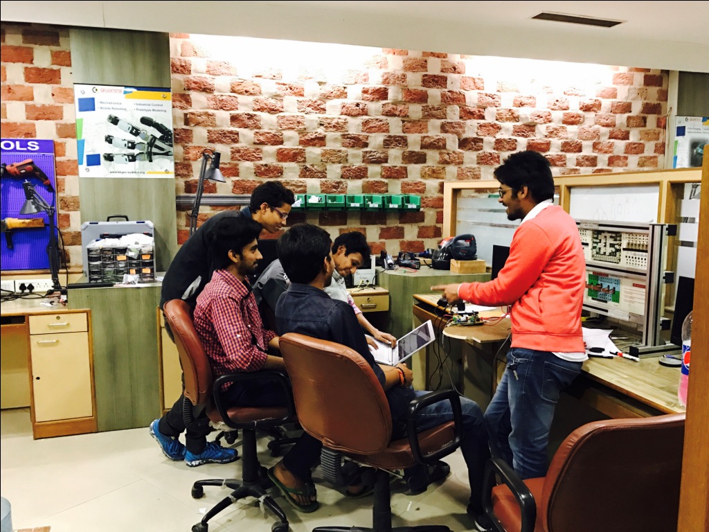
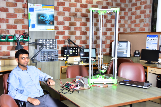
About Me...My name is Apoorv Vats. I am working in the capacity of Assistant Professor in the Department of Electrical and Electronics Engineering at Ajay Kumar Garg Engineering College Ghaziabad, India. Currently I’m also associated with AKGEC Skills Foundation (an initiative by AKGEC) as Scientific Officer. My AcademicsI am Electrical Engineer by profession completed Masters specialized in Power Electronics & Drives from MNNIT Allahabad, India.(Resume) To me engineering is a interesting and absorbing subject where there is always something new to learn. I’m attracted by its dynamic environment in which new materials, technologies and processes are being developed all the time. For me personally there is a lot of satisfaction to be gained from challenging yourself and then achieving. At school I studied hard to understand and master related subjects and had the opportunity to take part in several interesting projects that allowed me to see at first hand what engineering was all about. Throughout my college years I have also been fortunate enough to have family and tutors around me who have been there to support me in my career goals. They have assisted me to make decisions that I am sure will have a positive and great effect on the rest of my life. Few months ago I came to know about Fab lab. I liked the whole idea of sharing knowledge and using the fablab to create something resourceful to oneself and to the community. |
Smart Office Table
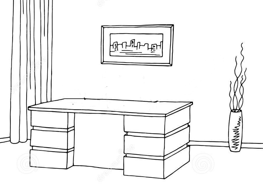
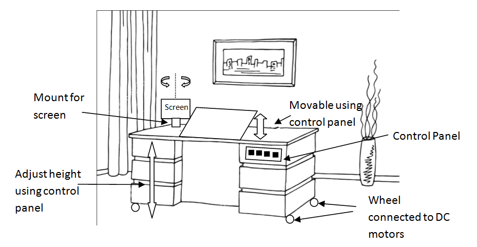
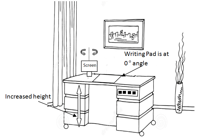
In this project it is decided to designed a smart office table. It will be smart in the sense we can ajust the angle of writing pad according to our need using control panel. If angle is 0 degree wrt to horizontal axis, it will be a table like it is having no writing pad.
Another feature in this table will be the adjustable hieght. We can adust height according to our need. The height can be increased as much as to work while standing on the floor. In smart table we can rotate the screen of computer using control panel.
This table can be used as a portabe table, if you want to work at remote site inside a container just take this table and create your portable working place.
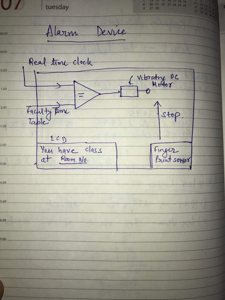
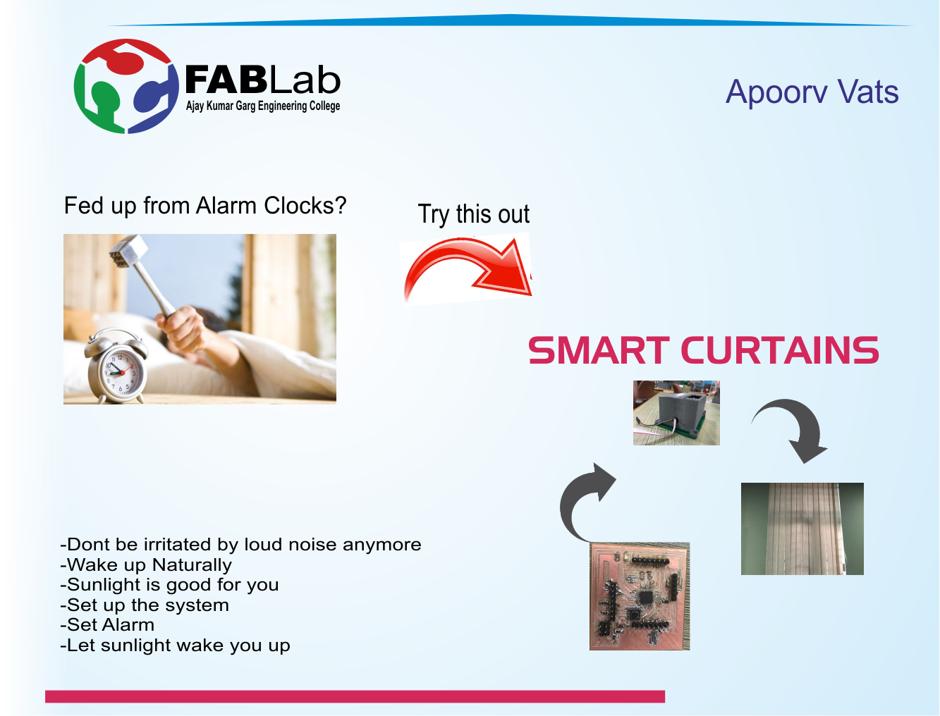


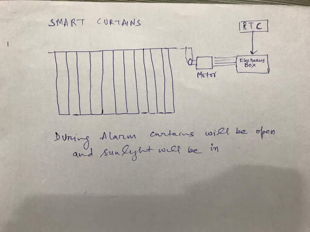
This alarm system will help to wake you up. The curtains will be open and sunlight will be in during the alarm time.
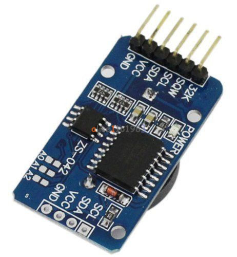
For real time monitoring i will be using DS3231 module. The DS3231 is a low-cost, extremely accurate real-time clock (RTC) .The RTC maintains seconds, minutes, hours, day, date, month, and year information. The date at the end of the month is automatically adjusted for months with fewer than 31 days, including corrections for leap year. The clock operates in either the 24-hour or 12-hour format with an AM/PM indicator. Two programmable time-of-day alarms and a programmable square-wave output are provided. Address and data are transferred serially through an I2C bidirectional bus.
To learn how to work on this module i followed some online tutorials the link for which is given here. I downloaded the ds3231 library for arduino from this link. After downloding this library paste this folder inside the library of arduino at local disk. After this i tried examples given in this library to have some idea about this device.
EXAMPLE 1: To set time in the device
This code is used to set the time in your device. I will be using Arduino MEGA to set the device time.I used the DS3231 RTC library for Arduino written by Petre Rodan (has licenced his work under GNU GPLv3).
Copyright notice for this file
#include
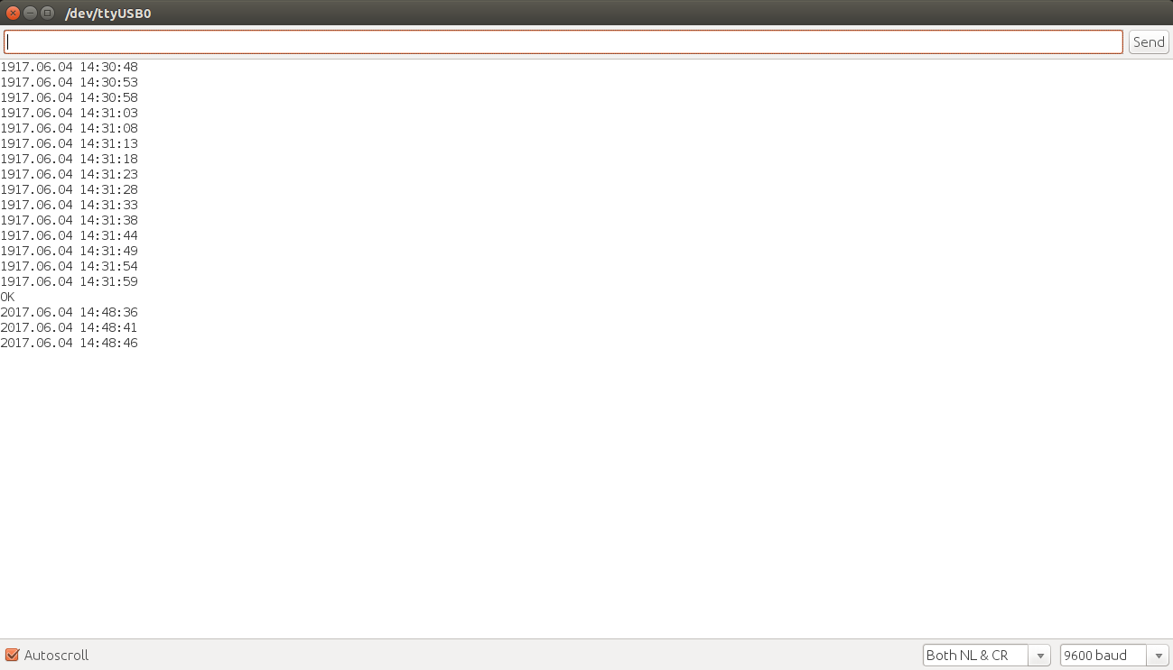
OUTPUT
The ouput is shown below. Previously RTC module was showing some non updated time and date. Now after passing T364814704062017 into the serial window, the date and times is updated.
EXAMPLE 2: ALARM
// during an alarm the INT pin of the RTC is pulled low
//
// this is handy for minimizing power consumption for sensor-like devices,
// since they can be started up by this pin on given time intervals.
#include
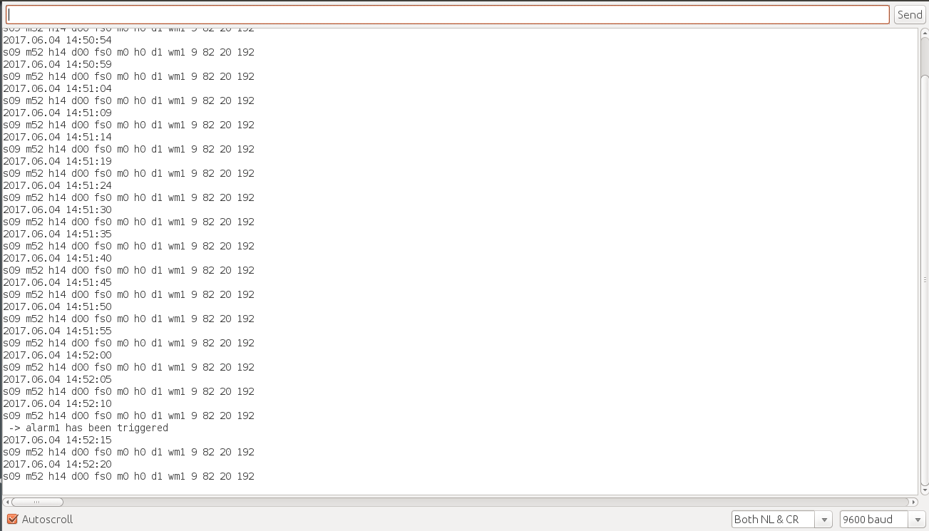
OUTPUT
Now to trigger the alarm above code is loaded into the board. According to the set alarm in the program the output is shown below
Files for the above codes are given below. All these codes are available in examples when you add the ds3231 library.
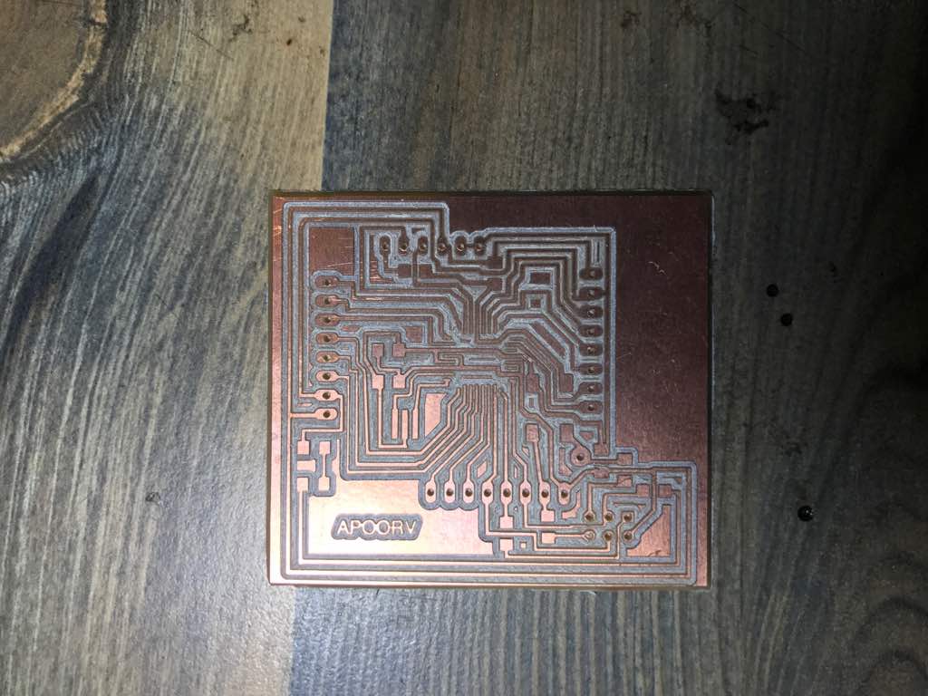
I will be using fabkit v0.3 as my input board with some changes. First i followed the tutorial given in the link here. The next step i made some changes and added ISP pin in the board for which snapshots are given below. There was no need to makeany other specific changes in the board other thanISP pin so that it can be programmed easily. I followed the above tutorial to learn how to burn the bootloader into the board. Since this board was milled using laser previously so the file which i downloaded from above link are not for milling on CNC machine. So i also edited the board file to mill it using Roland SRM20.There was no need to makeany other specific changes in the board other thanISP pin so that it can be programmed easily.
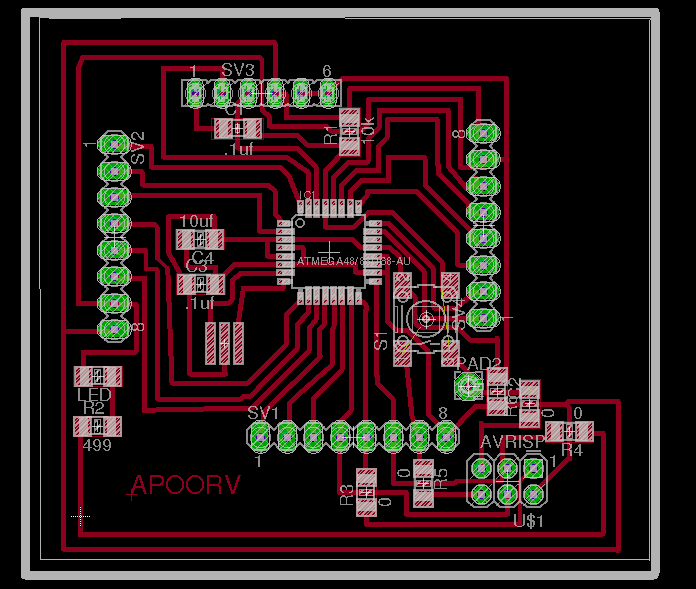
The milled board using Roland SRM 20 is shown in figure below.
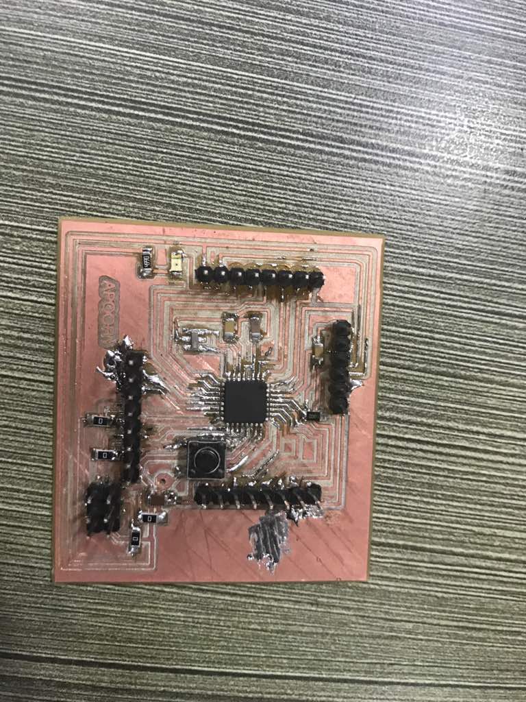
Stuffed Board
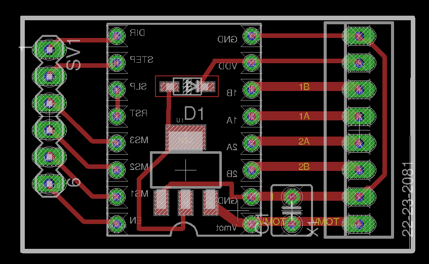
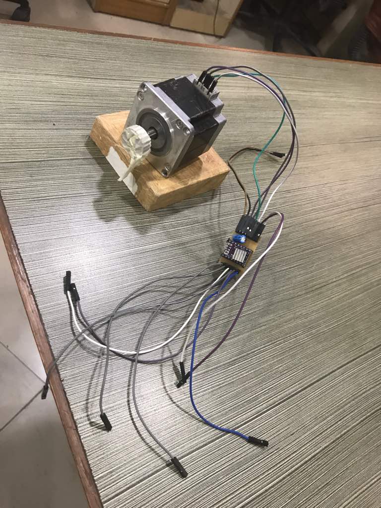
Driver Circuit
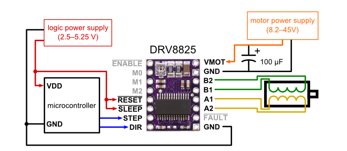
For driving of Stepper motor I will be using DRV8825 stepper motor driver
The board for output devices is shown below
Now next step is to program the board so that motor rotates for set number of rotations when alarm is triggered in the input device. For ths program is shown below.
// during an alarm the INT pin of the RTC is pulled low
//
// this is handy for minimizing power consumption for sensor-like devices,
// since they can be started up by this pin on given time intervals.

#include
#include "ds3231.h"

#define BUFF_MAX 256

// time when to wake up
uint8_t wake_HOUR = 20;
uint8_t wake_MINUTE = 17;
uint8_t wake_SECOND = 9;

const int stepPin=12;
int a=1;
const int dirPin=13;
const int MS1=9;
const int MS2=10;
const int MS3=11;
const int ENBL=8;
const int LEDpin=13;

// how often to refresh the info on stdout (ms)
unsigned long prev = 5000, interval = 5000;

void set_alarm(void)
{

    // flags define what calendar component to be checked against the current time in order
    // to trigger the alarm - see datasheet
    // A1M1 (seconds) (0 to enable, 1 to disable)
    // A1M2 (minutes) (0 to enable, 1 to disable)
    // A1M3 (hour)    (0 to enable, 1 to disable)
    // A1M4 (day)     (0 to enable, 1 to disable)
    // DY/DT          (dayofweek == 1/dayofmonth == 0)
    uint8_t flags[5] = { 0, 0, 0, 1, 1 };

    // set Alarm1
    DS3231_set_a1(wake_SECOND, wake_MINUTE, wake_HOUR, 0, flags);

    // activate Alarm1
    DS3231_set_creg(DS3231_INTCN | DS3231_A1IE);
}

void setup()
{
    Serial.begin(9600);
    Wire.begin();
    DS3231_init(DS3231_INTCN);
    DS3231_clear_a1f();
    set_alarm();
    pinMode(MS2,OUTPUT);
pinMode(MS3,OUTPUT);
pinMode(ENBL,OUTPUT);
pinMode(stepPin,OUTPUT);
pinMode(dirPin,OUTPUT);
pinMode(MS1,OUTPUT);
pinMode(LEDpin,OUTPUT);
digitalWrite(MS1,LOW);
digitalWrite(MS2,LOW);
digitalWrite(MS3,LOW);
digitalWrite(ENBL,LOW);
digitalWrite(LEDpin,HIGH);
}

void loop()
{
    char buff[BUFF_MAX];
    unsigned long now = millis();
    struct ts t;

    // once a while show what is going on
    if ((now - prev > interval) && (Serial.available() <= 0)) {
        DS3231_get(&t);

        // display current time
        snprintf(buff, BUFF_MAX, "%d.%02d.%02d %02d:%02d:%02d", t.year,
             t.mon, t.mday, t.hour, t.min, t.sec);
        Serial.println(buff);

        // display a1 debug info
        DS3231_get_a1(&buff[0], 59);
        Serial.println(buff);

        if (DS3231_triggered_a1()) {
            // INT has been pulled low
            Serial.println(" -> alarm1 has been triggered");
            digitalWrite(dirPin,HIGH);
while(a==1)
{
for(int x=0; x<500;x++)


{

  digitalWrite(stepPin,HIGH);
  delayMicroseconds(1000);

  digitalWrite(stepPin,LOW);
  delayMicroseconds(1000);

  }
  a=0;
}
            // clear a1 alarm flag and let INT go into hi-z
            DS3231_clear_a1f();
        }
        prev = now;
    }
}
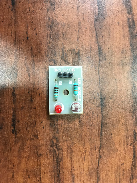
In order to control the alarm device a light sensor is also included in the module. This prototype will also have an advantage that the alarm will stop after sensing a set intensity of light.
Below is the LDR board to be included in the alarm device.
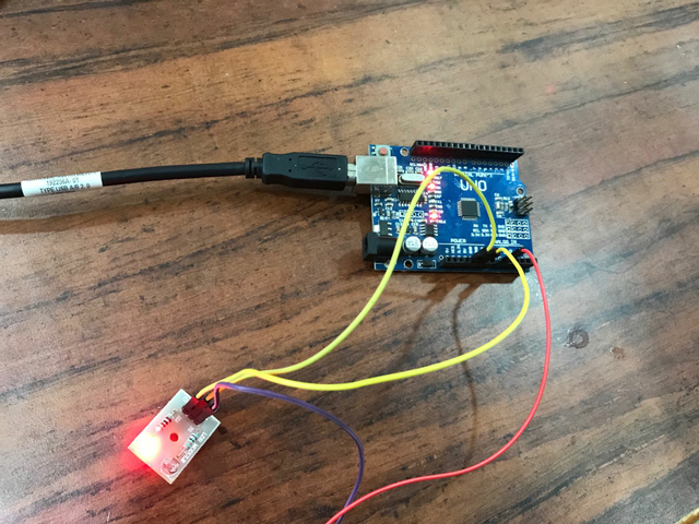
This module is tested using arduino UNO. Below you can find the screenshot of the result obtained from this module.
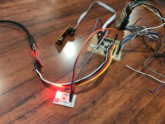
The LDR module is now integrated with Alarm device. According to the set alarm the device will open the curtains. When a particular intensity of light falls on the device the alarm will stop. LDR module on detection of light passes the signal to the alarm device to stop the motor.
The Ouput of the above program is shown below. The motor rotates when alarm is triggred. The number of revolution of the motor can be controlled from the program itself.
First i tried with Rack and Pinion mechanism to change the rotational motion of the motor into linear one. Then tested this mechanism using the following code.
In this code motor is rotated clockwise and anticlockwise for fixed number of steps.
const int stepPin=12;
int a=1;
const int dirPin=13;
const int MS1=9;
const int MS2=10;
const int MS3=11;
const int ENBL=8;
const int LEDpin=13;


void setup() {
  // put your setup code here, to run once:
pinMode(MS2,OUTPUT);
pinMode(MS3,OUTPUT);
pinMode(ENBL,OUTPUT);
pinMode(stepPin,OUTPUT);
pinMode(dirPin,OUTPUT);
pinMode(MS1,OUTPUT);
pinMode(LEDpin,OUTPUT);
digitalWrite(MS1,LOW);
digitalWrite(MS2,LOW);
digitalWrite(MS3,LOW);
digitalWrite(ENBL,LOW);
digitalWrite(LEDpin,HIGH);
}

void loop() {
  // put your main code here, to run repeatedly:

while(a==1)
{digitalWrite(dirPin,HIGH);
for(int x=0; x<150;x++)


{

  digitalWrite(stepPin,HIGH);
  delay(100);

  digitalWrite(stepPin,LOW);
  delay(100);

  }
  a=0;
}


while(a==0)
{digitalWrite(dirPin,LOW);
for(int x=0; x<150;x++)


{

  digitalWrite(stepPin,HIGH);
  delay(100);

  digitalWrite(stepPin,LOW);
  delay(100);

  }
  a=1;
}
}
The problem identified by me using this mechanism in my final project is the length of rack. The required length would be more which is again difficult to mount.

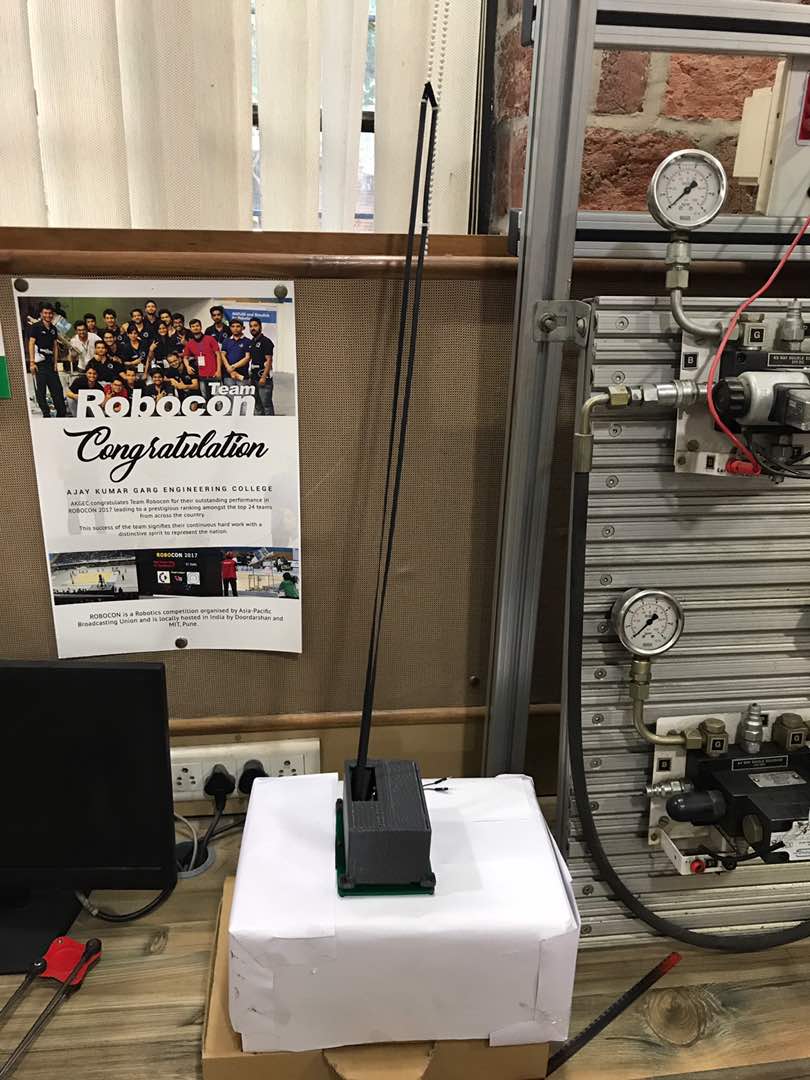
I also tried belt and pulley mechanism for my project. I concluded this mechanism is useful and easy to implement for my project.
I used the DS3231 RTC library for Arduino written by Petre Rodan (has licenced his work under GNU GPLv3). I modified this code to work for stepper motor. In this code alarm triggres according to the set alarm and it rotates the motor for fixed number of steps. This open the curtains at the alarm time.
Copyright notice for this file
Now to close the curtians motor is again rotated for the same number of steps but in reverse direction. In the final presentation the closing of curtians is shown immediately use to show the basic functionality of the code. Closing time can also be set according to the requirement through hard coding. Closing of the alarm in between is not implemented yet, but it could be implemented in the future.
// during an alarm the INT pin of the RTC is pulled low
//
// this is handy for minimizing power consumption for sensor-like devices,
// since they can be started up by this pin on given time intervals.

#include
#include "ds3231.h"

#define BUFF_MAX 256

// time when to wake up
uint8_t wake_HOUR = 19;
uint8_t wake_MINUTE = 04;
uint8_t wake_SECOND = 9;

const int stepPin=12;
int a=1;
const int dirPin=13;
const int MS1=9;
const int MS2=10;
const int MS3=11;
const int ENBL=8;
const int LEDpin=13;

// how often to refresh the info on stdout (ms)
unsigned long prev = 5000, interval = 5000;

void set_alarm(void)
{

    // flags define what calendar component to be checked against the current time in order
    // to trigger the alarm - see datasheet
    // A1M1 (seconds) (0 to enable, 1 to disable)
    // A1M2 (minutes) (0 to enable, 1 to disable)
    // A1M3 (hour)    (0 to enable, 1 to disable)
    // A1M4 (day)     (0 to enable, 1 to disable)
    // DY/DT          (dayofweek == 1/dayofmonth == 0)
    uint8_t flags[5] = { 0, 0, 0, 1, 1 };

    // set Alarm1
    DS3231_set_a1(wake_SECOND, wake_MINUTE, wake_HOUR, 0, flags);

    // activate Alarm1
    DS3231_set_creg(DS3231_INTCN | DS3231_A1IE);
}

void setup()
{
    Serial.begin(9600);
    Wire.begin();
    DS3231_init(DS3231_INTCN);
    DS3231_clear_a1f();
    set_alarm();
    pinMode(MS2,OUTPUT);
pinMode(MS3,OUTPUT);
pinMode(ENBL,OUTPUT);
pinMode(stepPin,OUTPUT);
pinMode(dirPin,OUTPUT);
pinMode(MS1,OUTPUT);
pinMode(LEDpin,OUTPUT);
digitalWrite(MS1,LOW);
digitalWrite(MS2,LOW);
digitalWrite(MS3,LOW);
digitalWrite(ENBL,LOW);
digitalWrite(LEDpin,HIGH);
}

void loop()
{
    char buff[BUFF_MAX];
    unsigned long now = millis();
    struct ts t;

    // once a while show what is going on
    if ((now - prev > interval) && (Serial.available() <= 0)) {
        DS3231_get(&t);

        // display current time
        snprintf(buff, BUFF_MAX, "%d.%02d.%02d %02d:%02d:%02d", t.year,
             t.mon, t.mday, t.hour, t.min, t.sec);
        Serial.println(buff);

        // display a1 debug info
        DS3231_get_a1(&buff[0], 59);
        Serial.println(buff);

        if (DS3231_triggered_a1()) {
            // INT has been pulled low
            Serial.println(" -> alarm1 has been triggered");


while(a==1)
{digitalWrite(dirPin,HIGH);
for(int x=0; x<100;x++)


{

  digitalWrite(stepPin,HIGH);
  delay(100);

  digitalWrite(stepPin,LOW);
  delay(100);

  }
  a=0;
}

delay(1000);

while(a==0)
{digitalWrite(dirPin,LOW);
for(int x=0; x<100;x++)


{

  digitalWrite(stepPin,HIGH);
  delay(100);

  digitalWrite(stepPin,LOW);
  delay(100);

  }
  a=1;
}
            // clear a1 alarm flag and let INT go into hi-z
            DS3231_clear_a1f();
        }
        prev = now;
    }
}

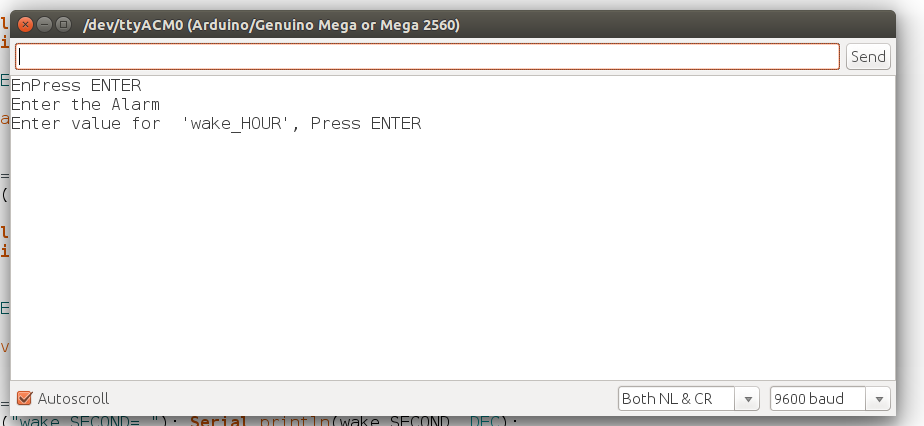
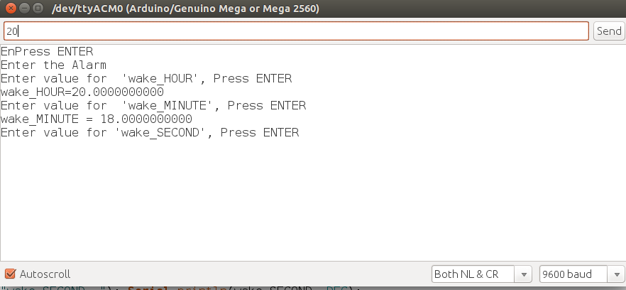
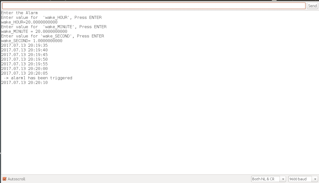
In the previous programs the alarm setting is hard through har coding. Below you can find the modified program in which alarm can be set by the user through serial monitor window.
I also tried working with processing to make GUI for my alarm system. I followed the tutorial given on this link. The GUI made using processing is shown below.
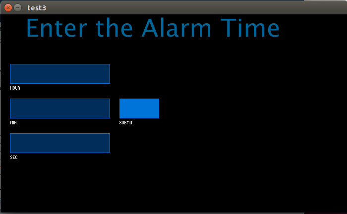
Below you can find the code written in processing. In this code the values of alarm time in the form of hour, minute and second is taken from the user. After pressing the submit button these values are taken in dummy variables in the code. These values are stored in variables, next task is to send these values to arduino through handshaking.
The problem whi while implementing handshaking is that, i am able to send only value of alarm hour from processing.
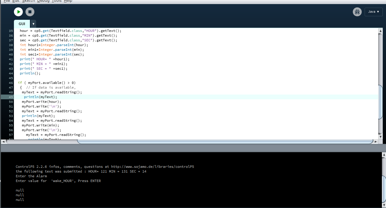
I will be contuinuing this work after learning more on coding part of the processing.This can be considered as one of the future developement in the spiral development of the project
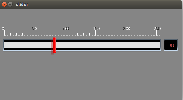
I will be adding slider for changing the motor speed and hence changing the opening and closing of curtains. I used processing and followed this linkfor code
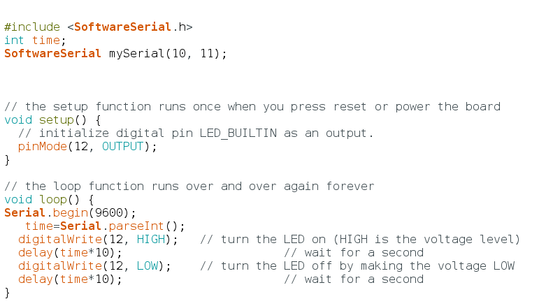
First i implemented the slider to control the delay of LED blinking.The snapshot of arduino code and processing code are shown below.
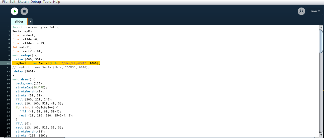
Next i implemented this slider to change the speed of stepper motor so that curtains can be opened with and closed with changing speed. I will be using this slider to change the delay timing in the main program. The code is attached below.
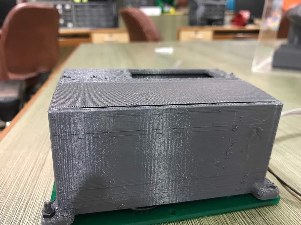
Making a molding and casting part would result in a product of better finish and it requires longer tools to reach depth of the model and such a lengthy tool isn't available in the lab. 3d printing provided a way to create a decent enclosure without too much complication required in design.
I used laser cutting to make initial test covering for the system.
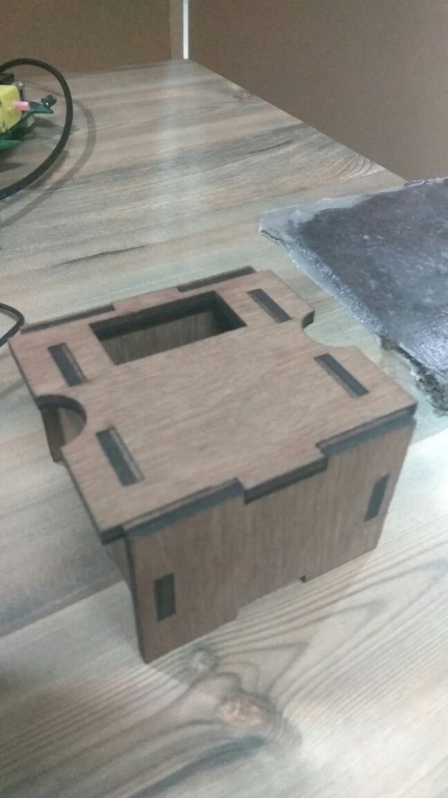
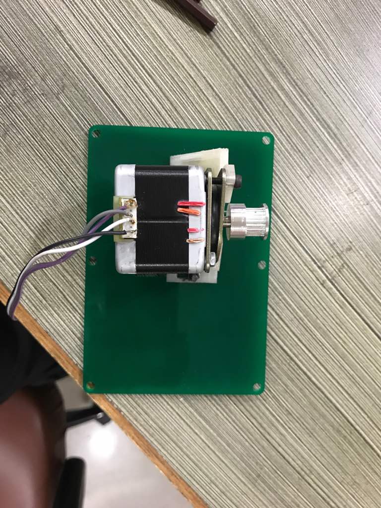
Casing for motor and packaging of the electronics is developed using NX.
The motor mount design is being developed using onshape, the snapshot for the same is shown below.
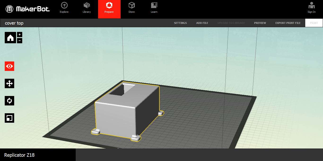
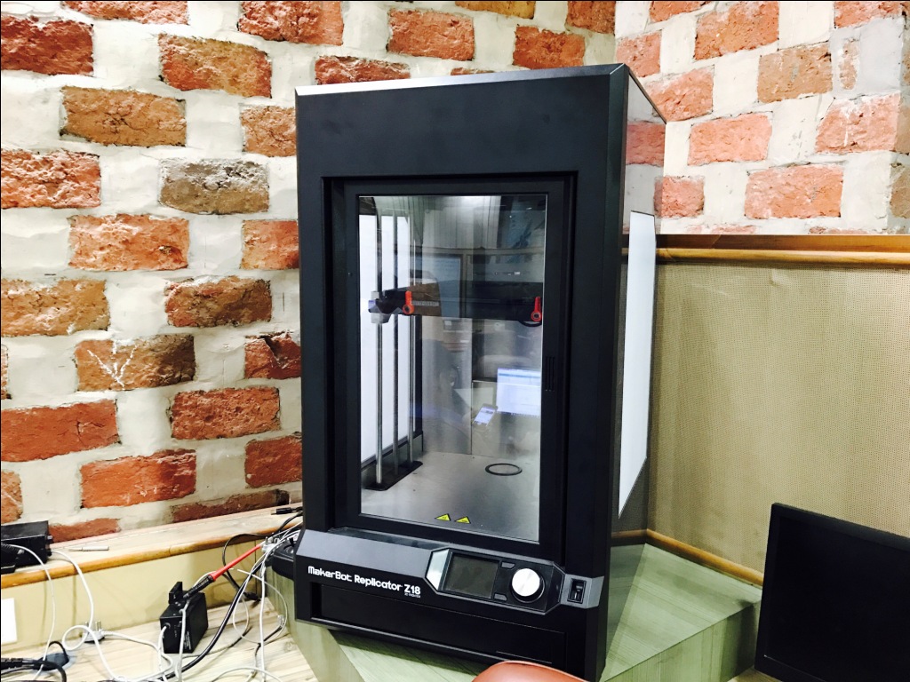
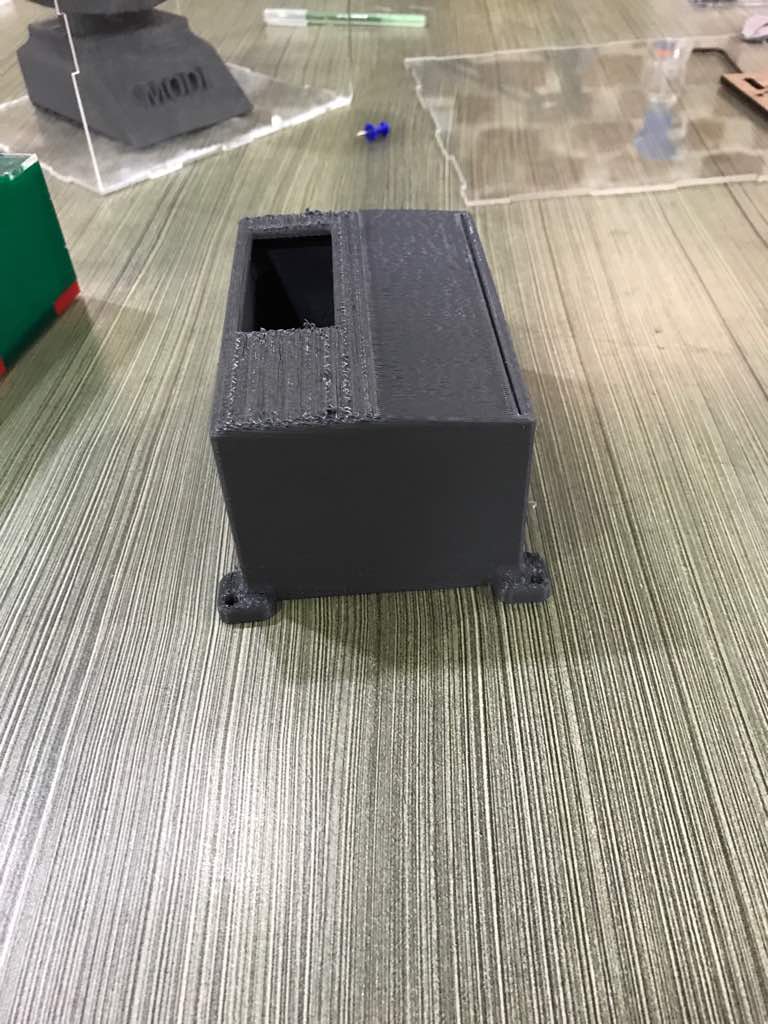
The above file is printed suing makerbot 3D printer.
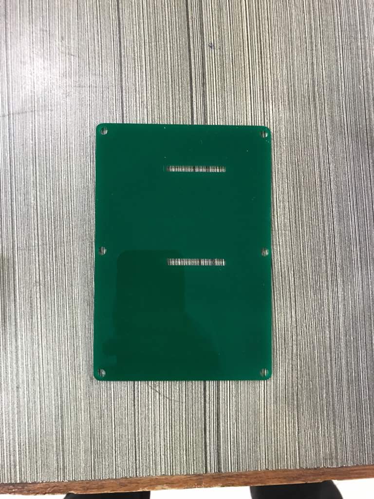
The base plate is developed using laser cutting machine.
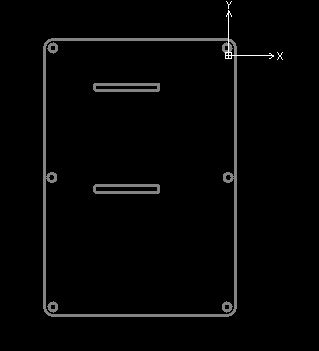
Laser Cutting of acrylic sheet.
Stepper Motor (available in fablab)
A4988 driver (2$)buy
DS3231 REAL TIME MODULE (2.5$)buy
Belt and Pulley Mechanism
Acrylic Sheet(8X4).buy
All other materials are easily available in our fablab