Electronics Design
Week 6: Assignment
This week's assignment is to redraw the echo hello-world board adding a button and led, while checking the design rules and making it. Optionally, we could simulate and measure its operation for extra credit.
Circuit Design
Steps
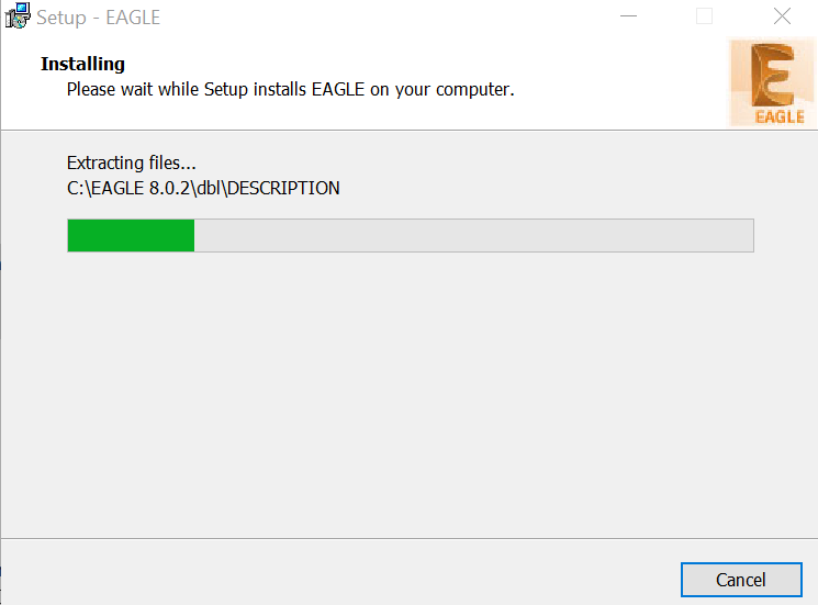
- I decided to use Eagle software to design my board. So, I went to the Eagle's site and downloaded the 64 bit Eagle software version 8.0.2
- I then loaded the much discussed FabLab component library, fab.lbr and placed it into the lbr folder in Eagle installation. This allowed me to load the FabLab components into Eagle.

- Since, this was the first time i am working on eagle software. So, have undergo the following tutorials.
- Fab Academy Tutorial
- Youtube videos by Jeremy Burns: Part 1, Part 2.
- One of my friend from Electronics department also helped me in understanding eagle software.
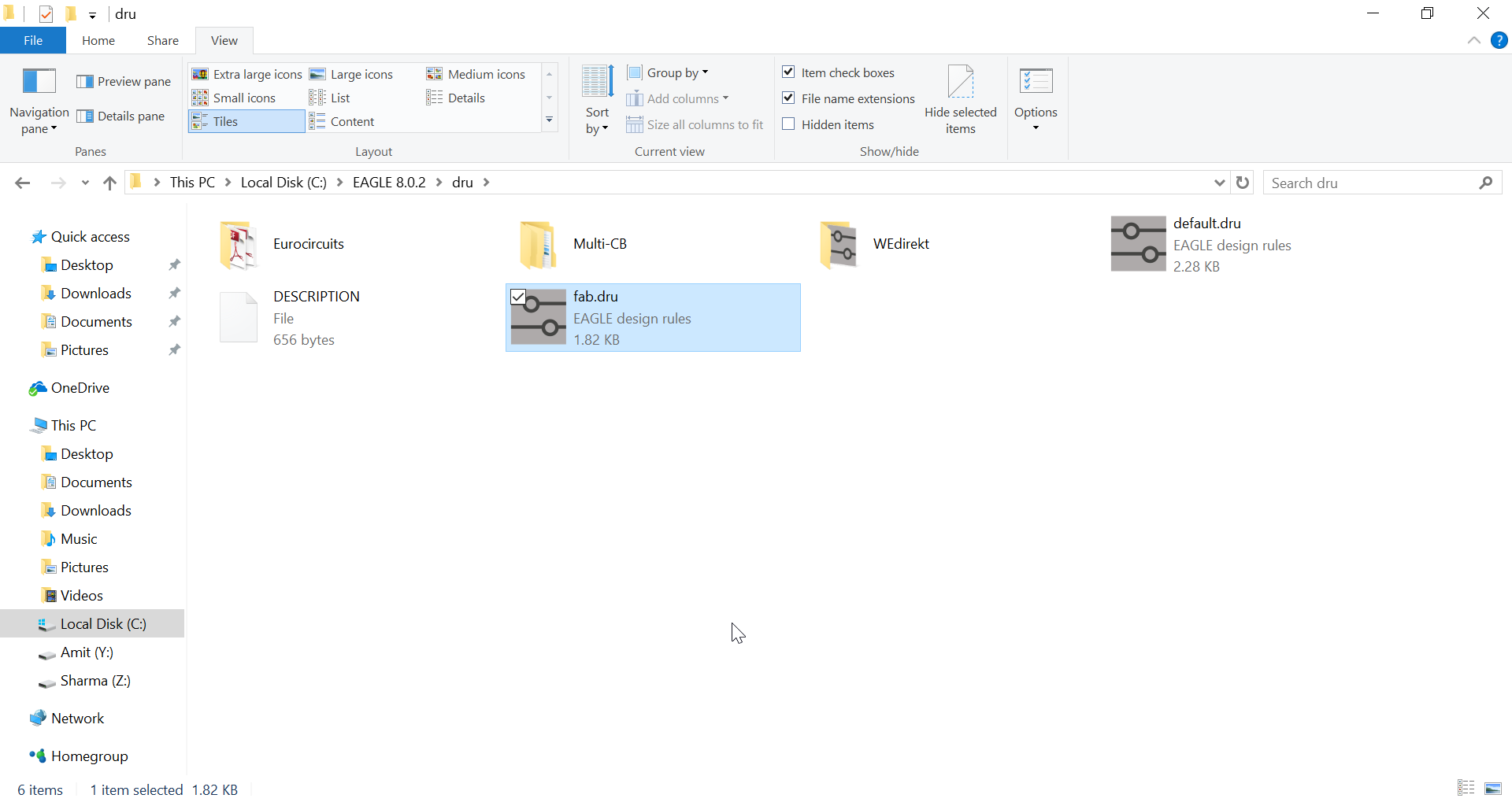
- Similarly, download fab.dru (design rules) and place it in the dru folder in the Eagle installation.
- Create a new project in Eagle software and add a schematic to it. Start adding components from the library (look for components directly under the Fab folder in the Add Dialog)
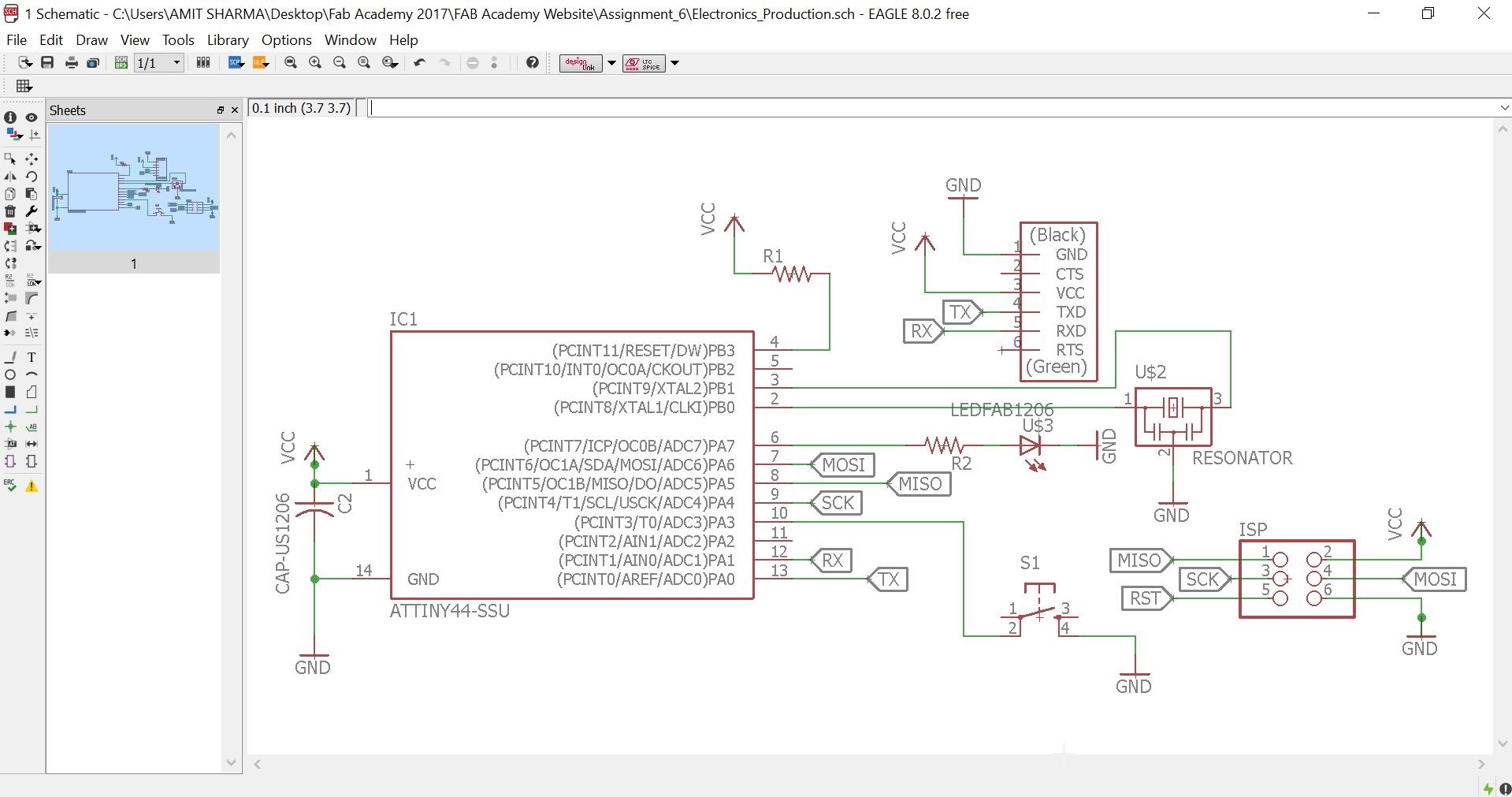
- Following components was added to the Schematic:
- ATtiny44-SSU: datasheet
- 20mhz resonator: ATtiny has an inbuilt 8mhz clock, but this one is faster and more accurate
- 6mm Switch Omrom
- AVR ISP SMD header: for programming the board
- FTDI SMD header: powers the board and allows it to speak to the computer
- 10K resistor x 2
- 1µF capacitor
- GND: Ground
- VCC: Power supply
Autocad 123D
I thought of using Autodesk 123D for the schematic desing but AutoDesk is closing this software in early april. So, I didn't felt like using outdated software. Autodesk is consolidating the required tools and features into key apps such as Tinkercad, Fusion 360, and ReMake.

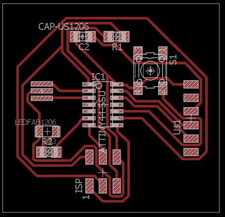
Layout
With the schematic done, switch to board view. At First, I attempted Autorouting. But, I was not getting 100 percent optimised value. So, afterwards I did manual routing and the final layout is shown below.
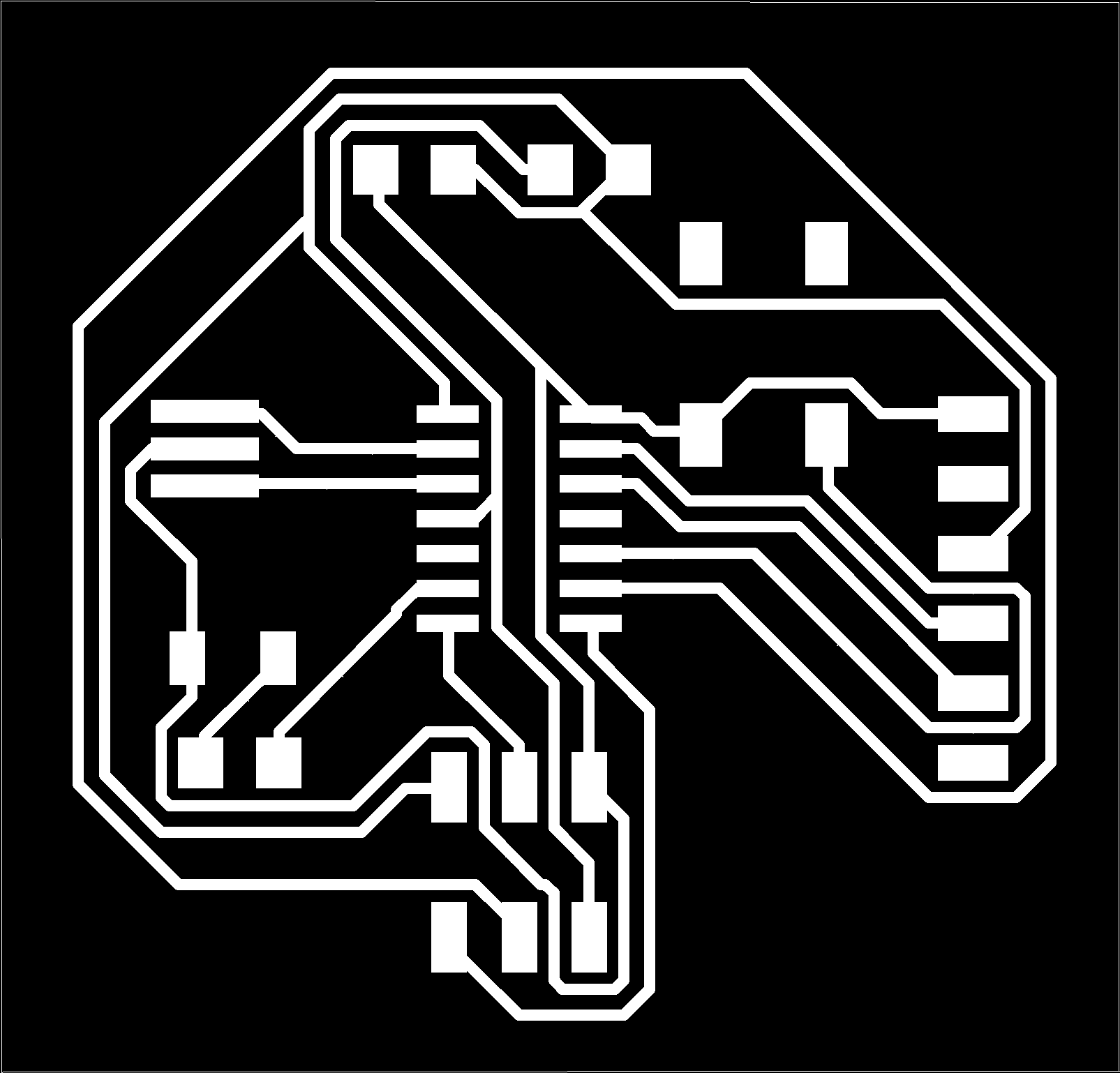
Milling
Export the layout as a monochrome png at 1000 dpi and also create the outline image for milling, as shown below.

Steps for Milling
- Made schematic of my board using Eagle 8.0.2. After completion of my schematic, I switched to board view and routed my board and exported the monochrone image (.png). This .png image is vectorized using Inkscape and saved as .eps
- .eps file is imported to Aspire 8.0 and it's tool path is created for the routing. After creating the tool path .rld file is generated.
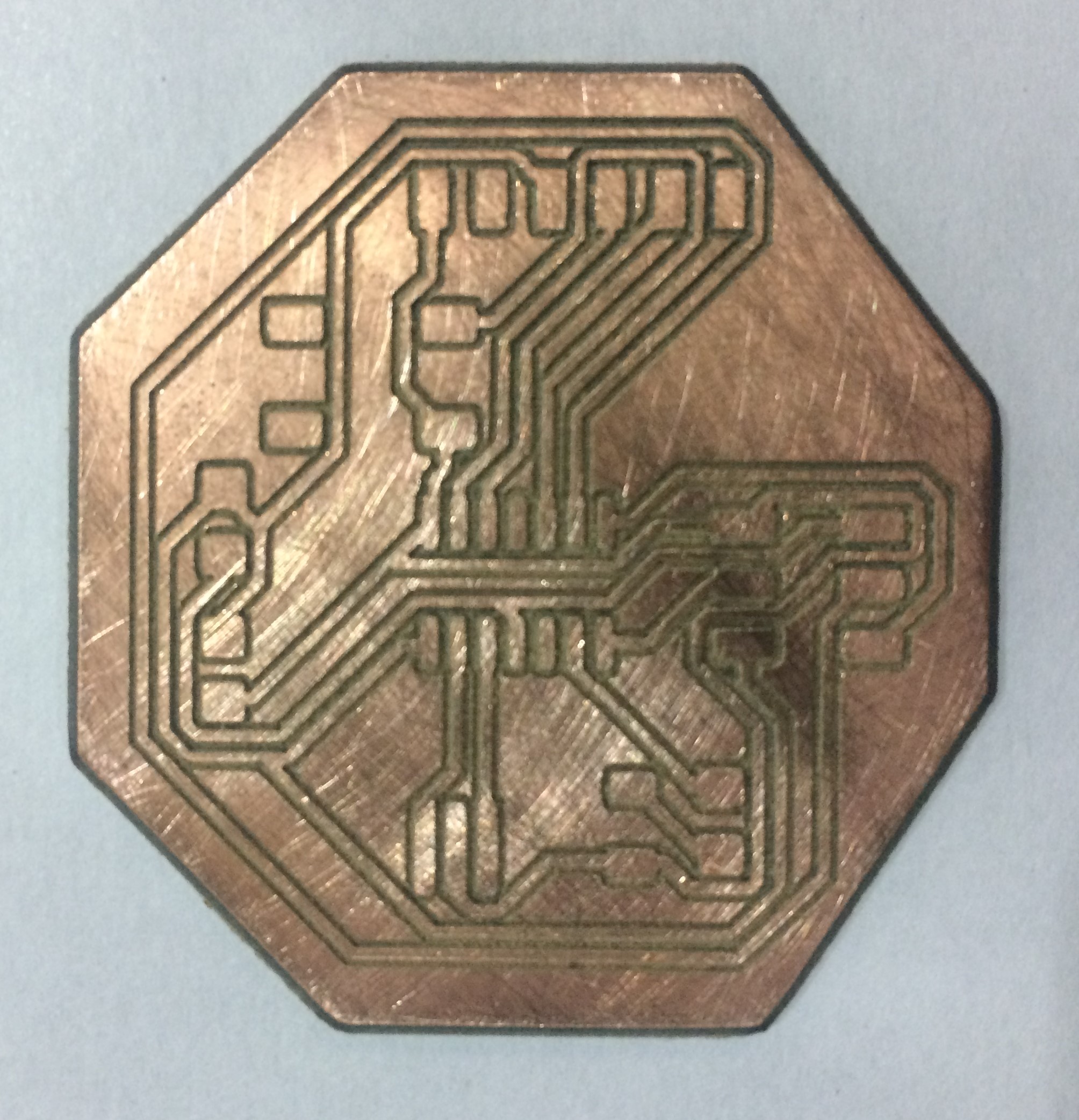
- .rld file is feed to the Roland EGX-600 machine for milling the board. Final milled board is shown below:
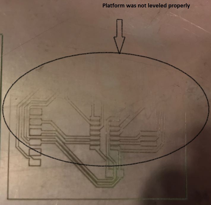
Point to be ponder while milling and problems faced by me during Milling
- Make sure the base of the machine is leveled. otherwise you will face the following problem.
- Make sure while cutting the traces and outline, origin is same.
- Space between the traces should be sufficient, to avoid any short circuiting.
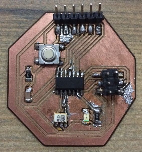
Stuffed Board
Testing the board
Steps
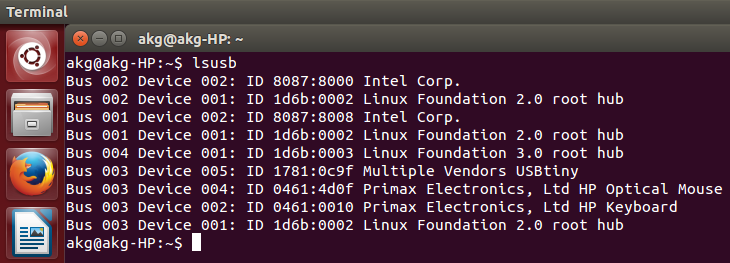
- Make sure your FABISP is connected to the computer. To do so use the command line as shown below.
- To check whether, the fuses are connected properly, use the following command line.
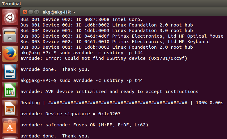
- If your ISP is detectable and fuses are ok then it's time for programming your board.
Programming the Board
Steps
- I used Arduino 1.8.1.0 for programming my board. Therefore, first step was to download it.
- Next step is to add ATtiny44A to the library of the Arduino. Reference can be made on this link ATtiny44A addon.
- Connect FabISP to the computer and hello FTDI to the ISP using the 6pin header cable.
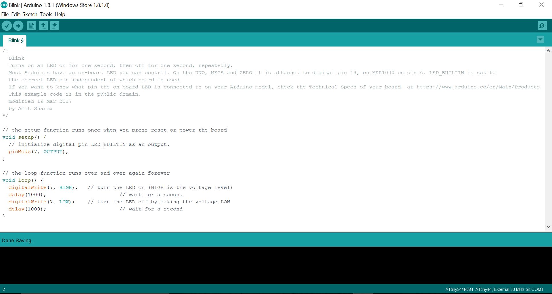
- Following parameters need to be set in the arduino software, as marker in green below:
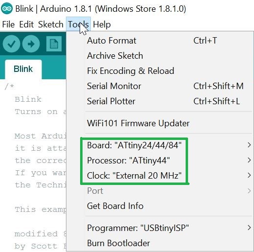
- Use Burn Bootloader, i.e. last option in tools menu bar.
Blink Led Programming
echo Hello Board Programming
Steps
- Download Neil's Hello world program and it's Hello world program.
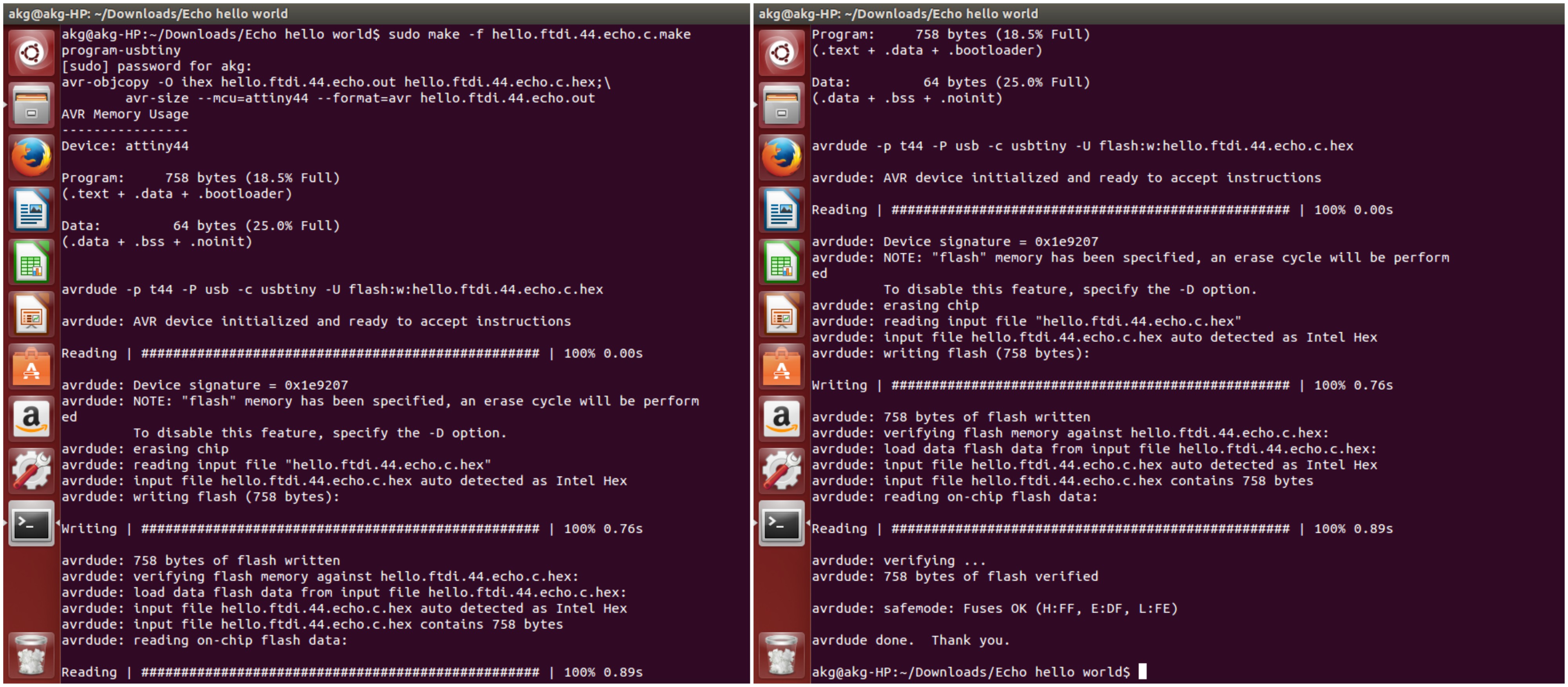
- Next step is to burn your program in the ISP, for that move to the folder where both the program file and make files is being saved and write the following command line in terminal.
sudo make -f hello.ftdi.44.echo.c.make program-usbtiny
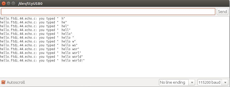
- Now connect your board with FTDI. FTDI is used for communication, it converts USB to serial communication.
- To test the program open Arduino and go to serial monitor. Type whatever message you want to display.