This week's assignment is to add an output device to a microcontroller board you've designed and program it to do something.
My Work Plan
Will Design and fabricate a board to make a servo motor run.
Will Document, how I made my board and provide my schematic and board files.
Illustrate suprises along the process.
Describe the problems and how I fixed them.
Document what the board does, what protocol it uses and what I learned along the process.
Step 1
After Neil's lecture on output devices, I had a detailed discussion with my local instructor regarding this week's assignment and since, I am a beginner in electronics. So, I decided to take up comparitively easier task, of designing and fabricating a microcontroller, which can derive a servo motor. Next day itself I started doing some research on Google & Youtube and had gone through, many tutorials on 'How to make Schematics on Eagle'; 'How to finalize Components, need to be connected on the board'; 'How a servo motor works'; 'What is the difference between servo motor and geared motor'; etc. After going through all these tutorials and videos, I got a brief idea about working of servo motors.
Step 2
Before, starting the designing of my board, I decided to run my motor using ARDUINO MEGA 2560. Steps to do so is as follows:
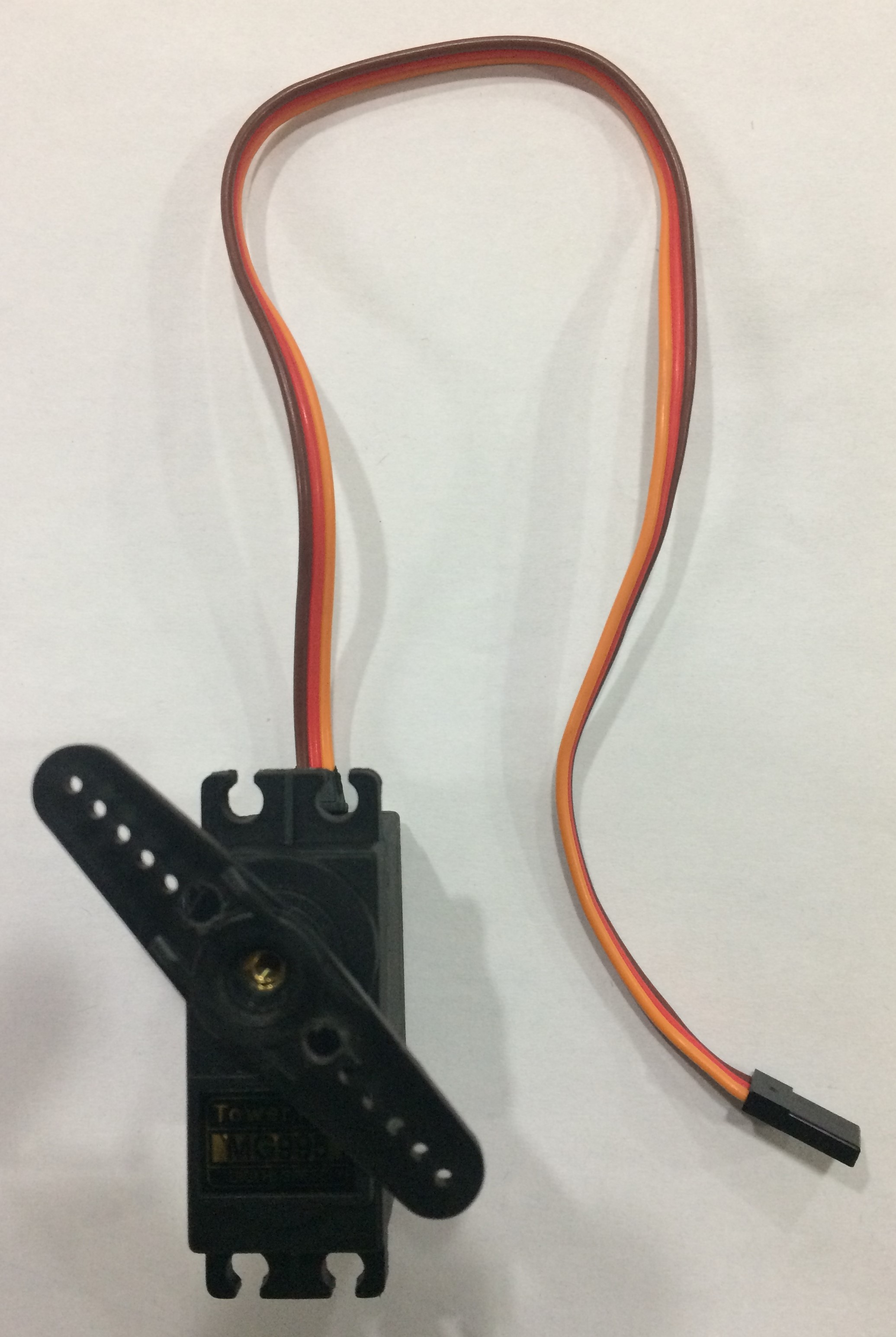
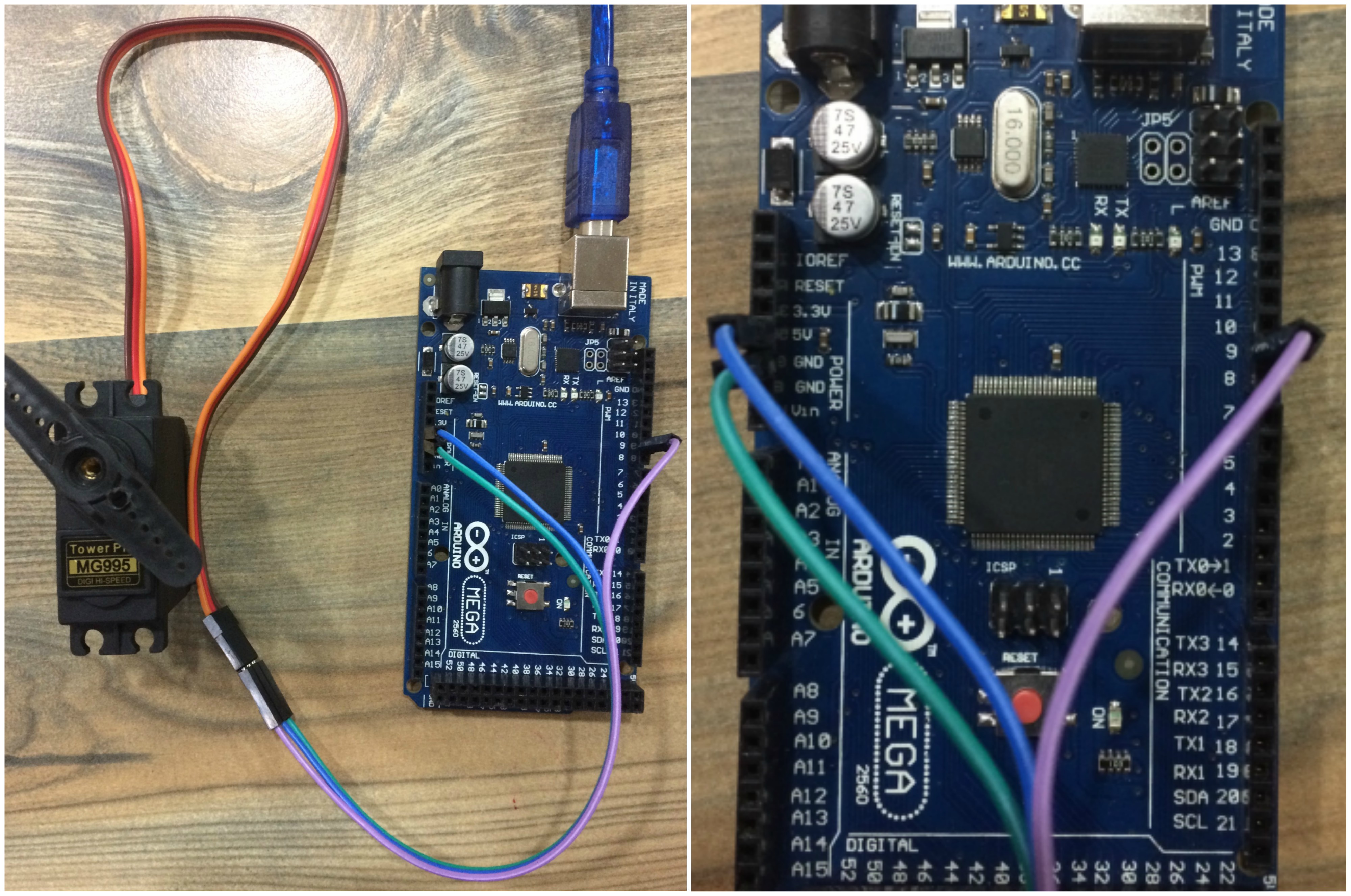
Identify the GND, Positive and Signal wire of servo motor in hand. In my case Brown = Ground; Red = Positive & Yellow = Signal. This data can be acquired by surfing a bit on google.
After identification of pins, Corresponding connections are made with ARDUINO MEGA 2560. i.e. Ground is connected to Ground, Positive is connected to 5V and Signal is connected to Pin 9.
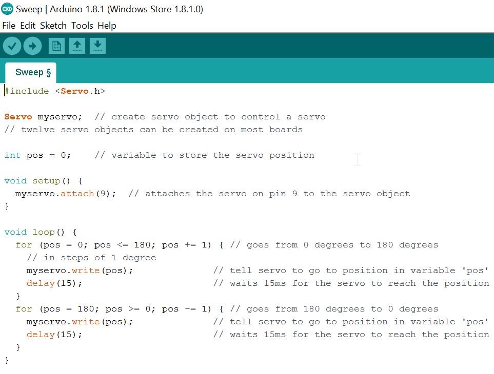
Now, I just pluged in the USB to the laptop, burned the arduino C program, which is availabe in examples of the arduino and my servo started reacting as shown below.
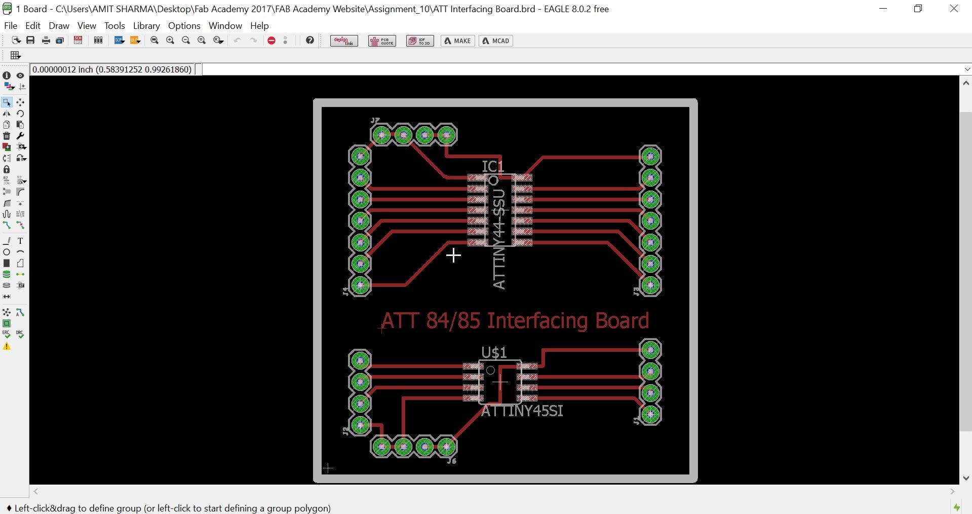
After tesing the servo motor with ARDUINO, I started making schematic diagram on EAGLE 8.0.2 for my microcontroller board. Since, in our Assignment 4 (Electronics Production) and Assignment 6 (Electronics Design), we have already studied about the production of PCB and I have followed that very same steps to produce my PCB, as discussed below:
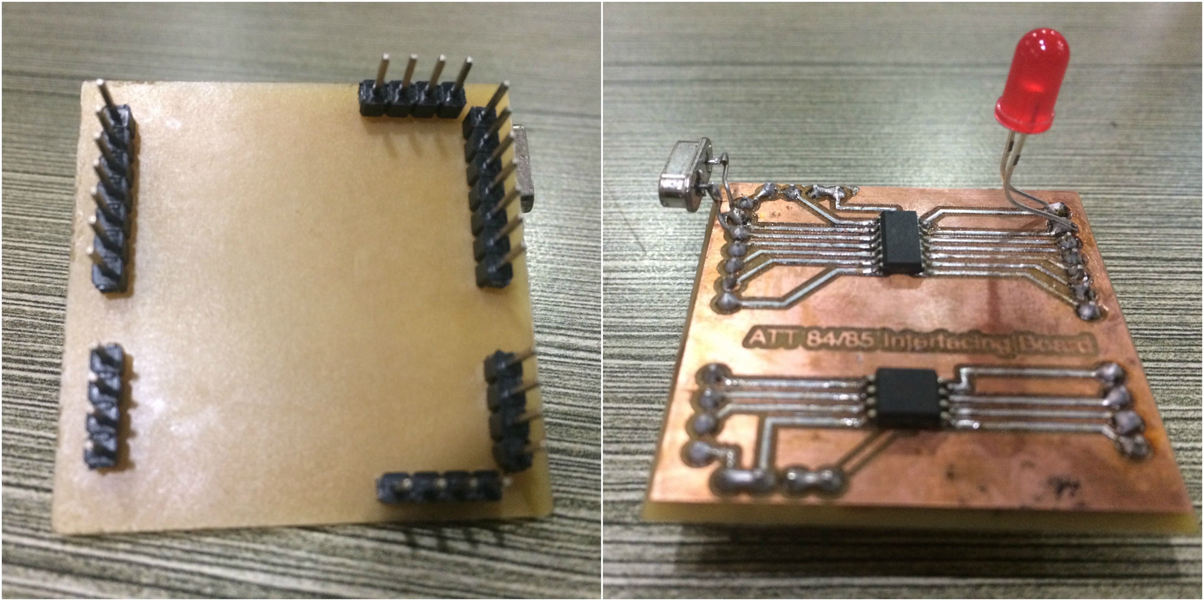
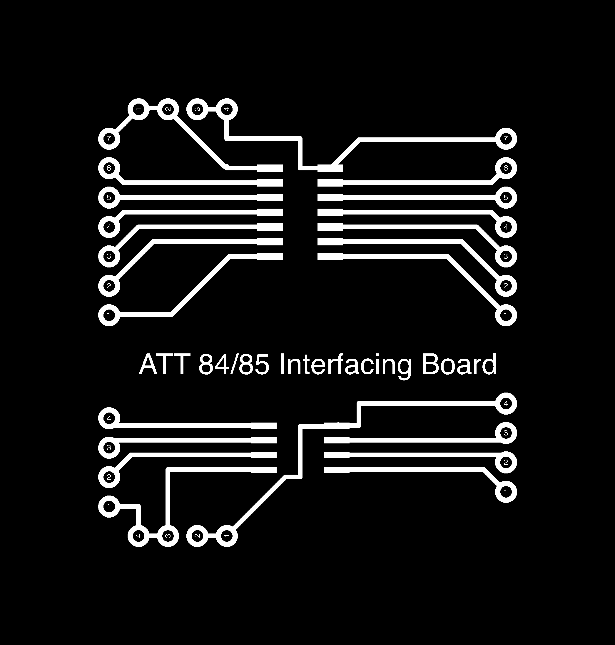
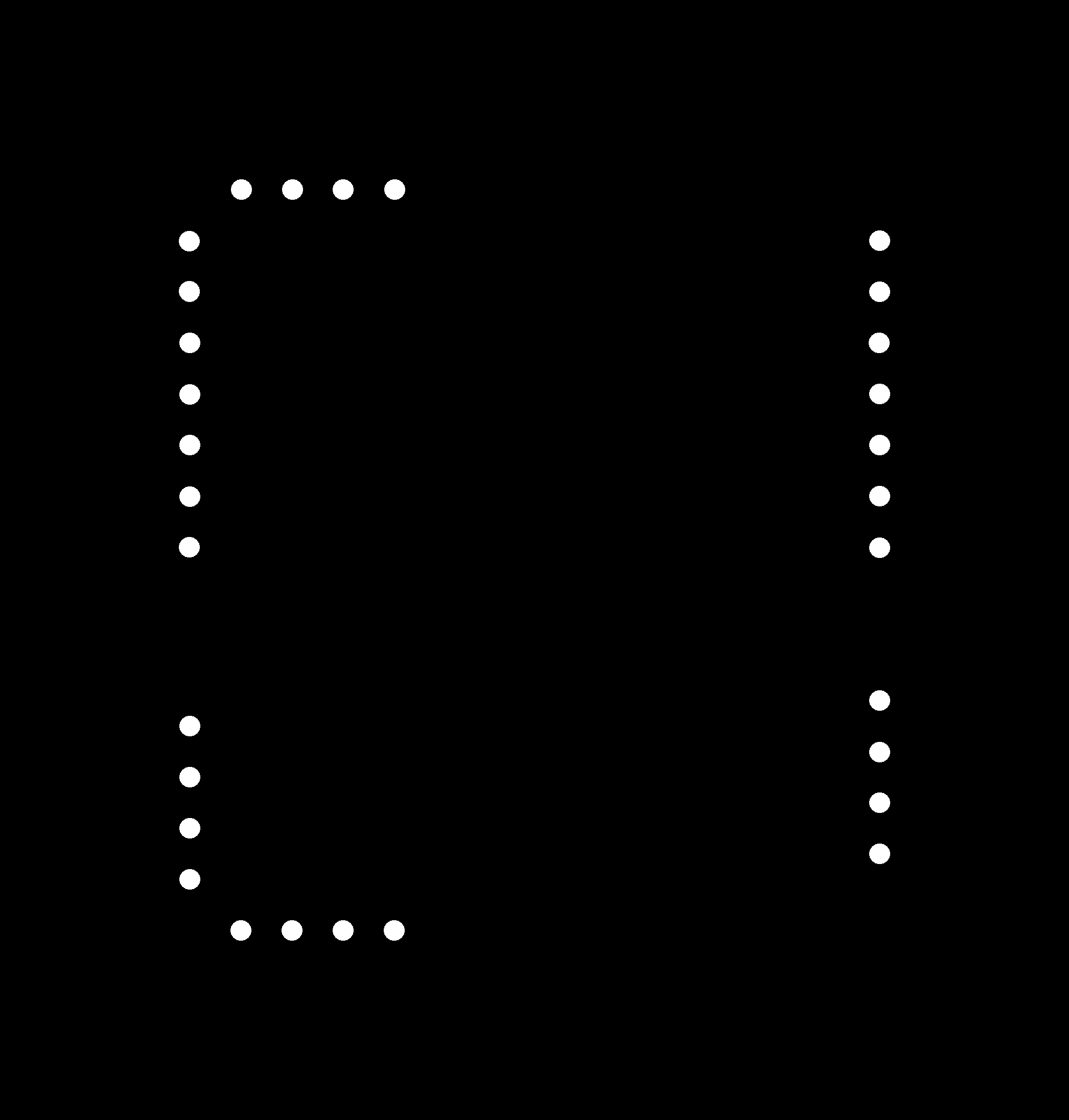
Prepared my schematic design on EAGLE 8.0.2 and then, developed board. I installed both Attiny 44 and Attiny 45 on my board, so that both can be programmed independentally for developing any application.
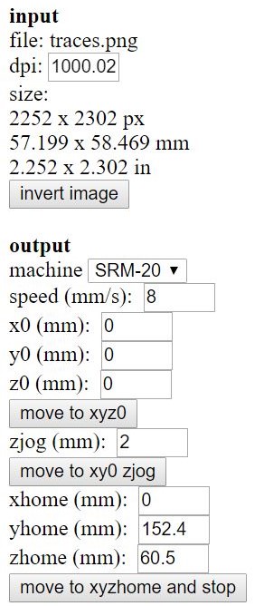
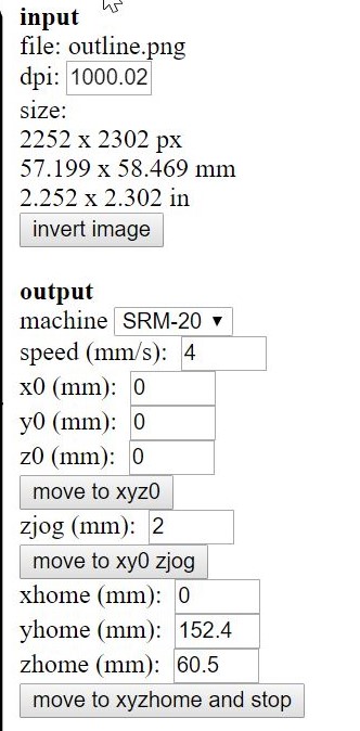
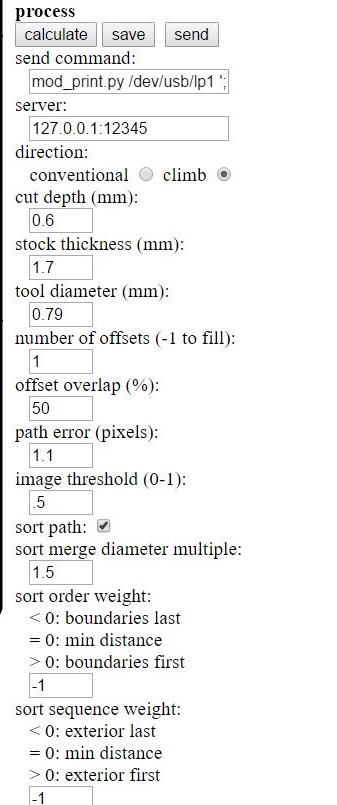
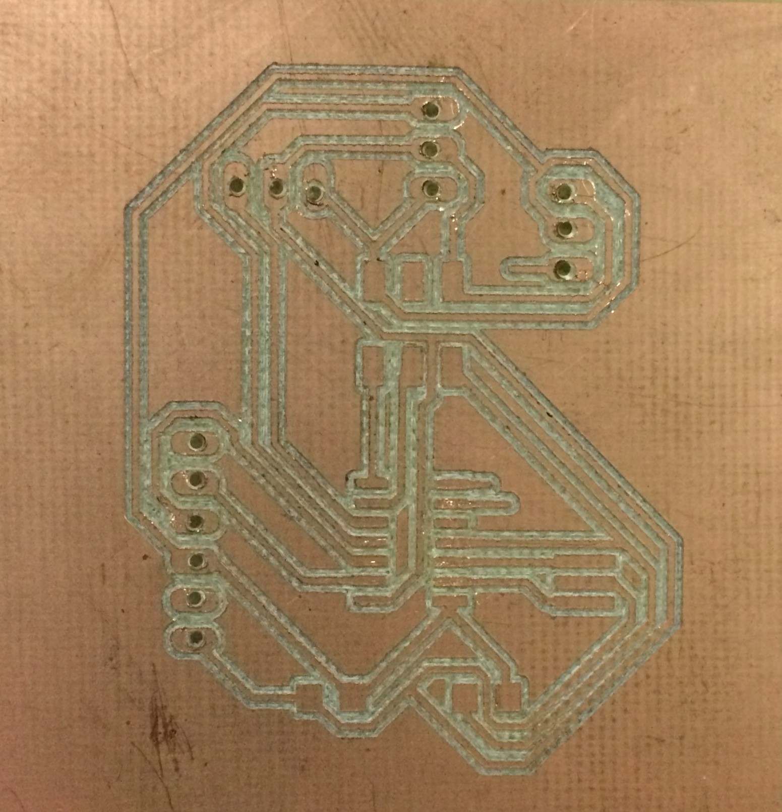
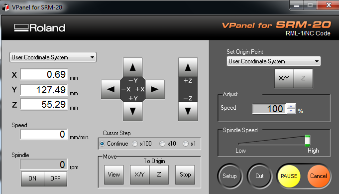
Created .rml files are fed to the V panel of SRM 20 Roland machine and board is developed.
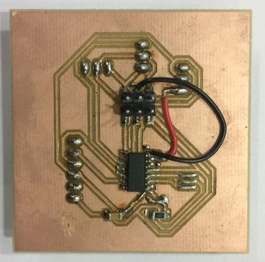
Developed board is stuffed with all the required components as shown below and Arduino C program is burned to the microcontroller.
Problems Faced
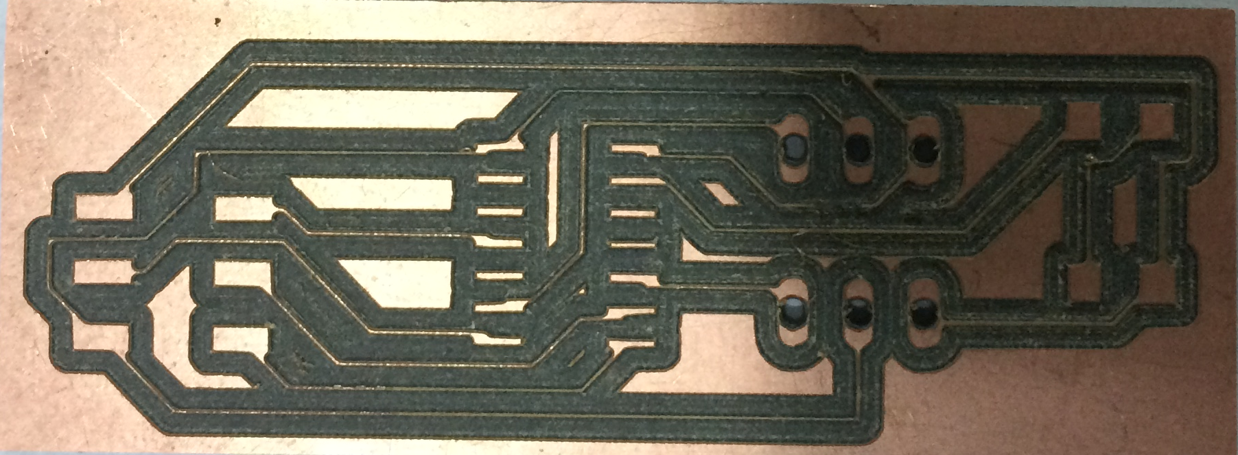
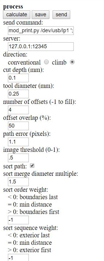
When I developed my first board, the developed traces was very thin and not appropriate for soldering, as shown below. Therefore, tool dia. is set from 0.2mm to 0.35mm in fabmodule and another board is routed. So, before actually going for routing make sure, right parameters are set, although this comes with experience.
After developing my second board with decent traces, when I got it checked by my Local Instructor, I found that my board is not having right components, connection and it won't work properly. Therefore, make sure while making the schematic that, right connections are given to components and correct component are placed onto the board.
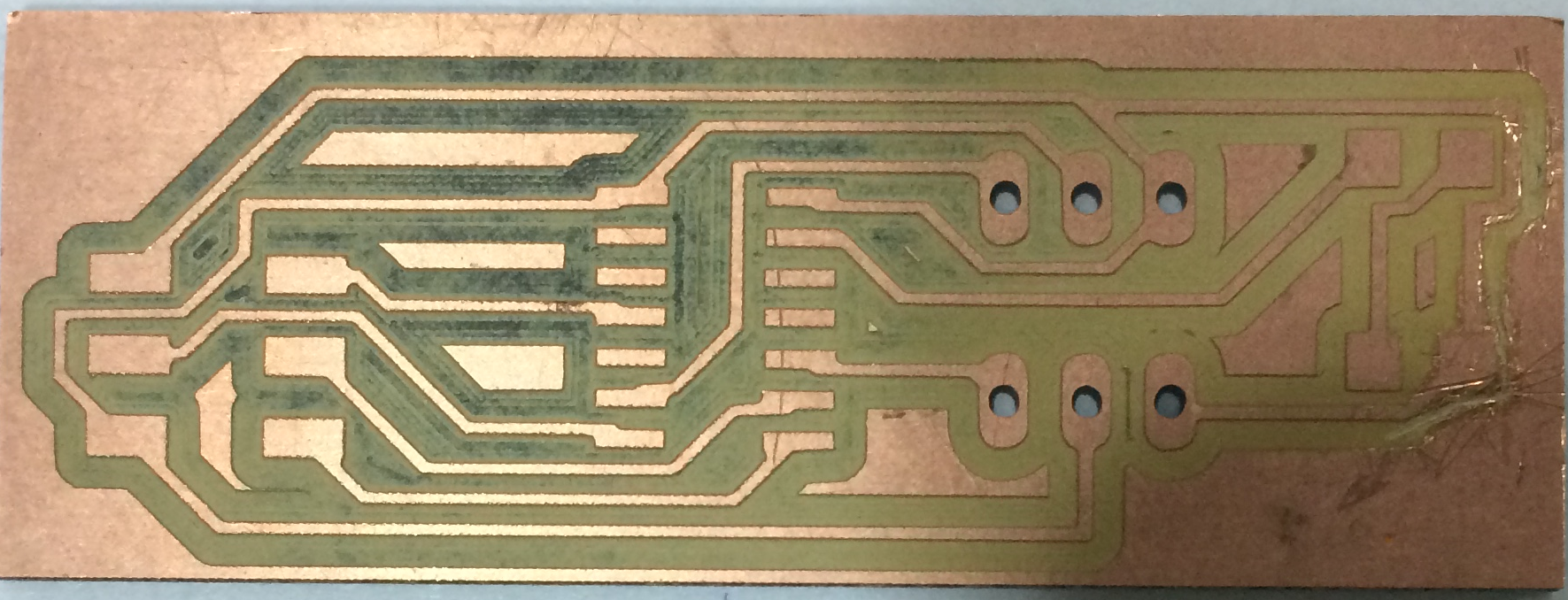
After two unsuccessful trials, I started making my third board, in consultation with my local instructor and this time all went well. But, while making the connections VCC and GND got interchanged and attiny 44 burnt. This is very important point to ponder and utmost focus should be paid while making the connections. I tried to replace the burnt attiny 44 with another one but while taking it out, copper traces also came out along with it. So, again I routed another board as shown above and stuffed it with the mentioned components.
With the developed board, using attiny 45, I was not able to burn bootloader because of the error "mismatch signature". I tried understanding this error but didn't get any satisfying explanation.
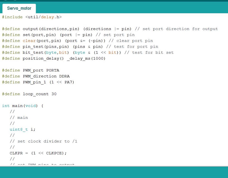
Afterwards I tried attiny 44 and basic codes from the examples of arduino is dumped but no output is detected, that's because signal to servo motor should be given from PA6 or PA7 pin, which I didn't do. Therefore no PWM is generated.
I created one more board, rectifying all the previous mistakes i.e. Signal to servo motor is given to PA7 of attiny 44.
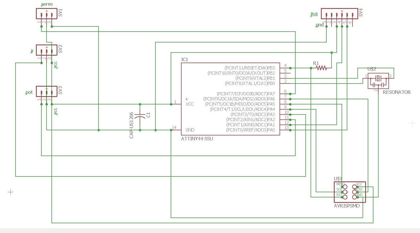
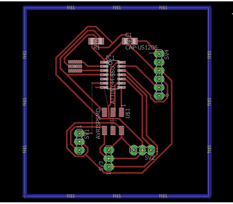
Schematic of the new board
This time while designing this board, I gave provision for IR distance measuring sensor also. So, that this same board can be used for Input devices assignment.
After converting Neil's C (two-channel, software PWM) program for one channel, I burned it to the microcontroller (attiny 44) and started working but after running for 1-2 minutes laptop was turning off. So, I connected it to the destok and it worked fine after words.
Questions
Why Laptop was getting turned off after dumping the arduino program to the microcontroller?

