I will do a wall-mounted drawing machine with Charlie. He had the initial design in Fab Academy 2016; you can see his animation and his prototyping here. He is now in the UK and I am in Aalto Fablab so we will try to each do working prototypes at our respective ends. I will first make a cardboard half-size prototype and then the full size pieces from plywood. We want to use the stepper motors as rotational (not linear motion). UPDATE: Charlie will work on the mechanical design part and I will work on the electronics. I need to do this also to catch up on previous assignments.
Design considerations:
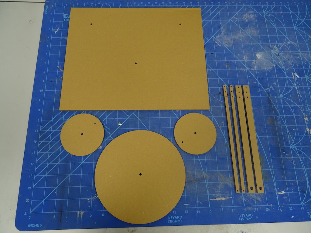
-a flat piece as the base, the size that will fit in the laser cutter (e.g. 610 x 914mm) (so change Charlie's design/dimensions)
-3 discs, the paper will sit on the biggest one (how? by magnets?)
-2 arms that can have different holes, the pen will be attached to the point they meet
-3 stepper motors. (Note: I don't have Nadya's kit here, Charlie has it there, so I'll make the dimensions according to whatever stepper motors, shafts, etc. we have here.)
-the discs will be programmed to move at different speeds so that will change the end result of the drawing (and the arm lengths can also be adjusted to make another change)
-a frame on the back of the base that can hide the motors and can be used for hanging the machine on the wall
-each piece should be thin enough - it should be light overall for hanging - but sturdy enough that the pen doesn't wobble
-will the pen stay in place when it is hanging vertically rather than sitting on a table?
-the gestalt board. (Charlie has one there, shall I make a new one here with Solomon's help?)
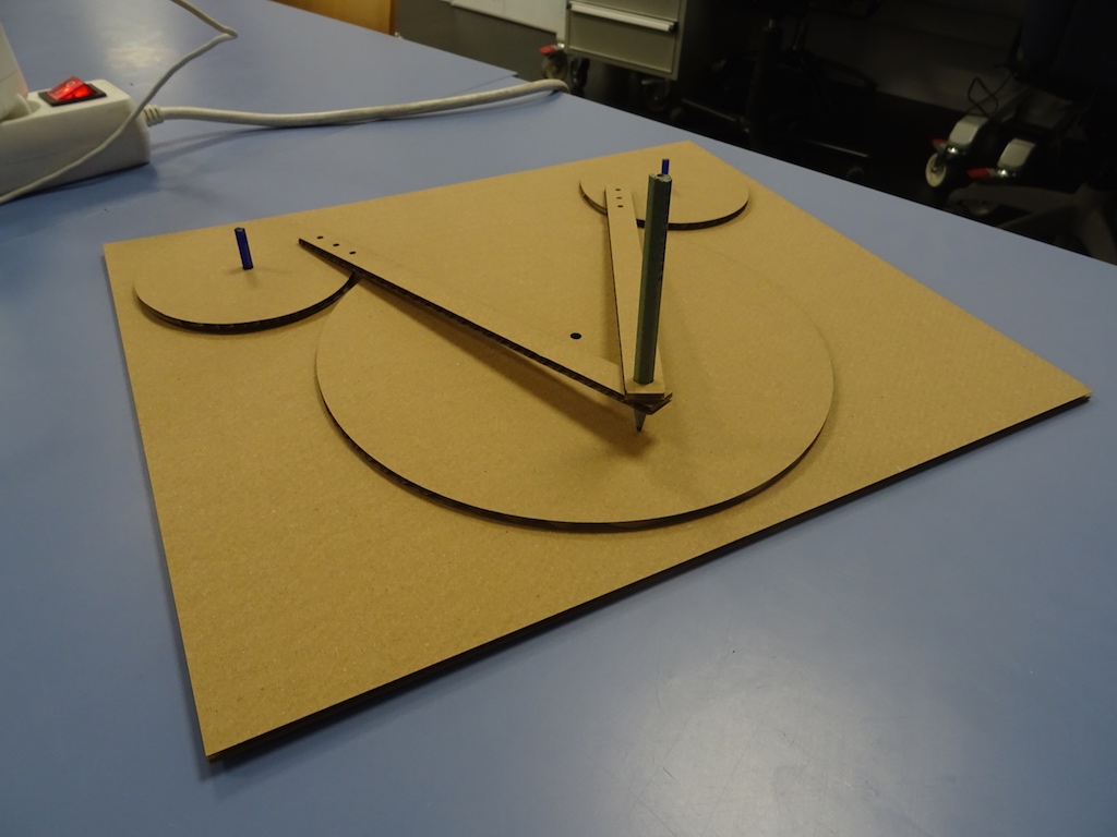
half-size cardboard cutout.
The arms are thin (aesthetically) - and I should make them fit a pen even at this half size scale. I also change the arms into rounded rectangles (also an aesthetic decision. Might do this later to the base rectangle also).
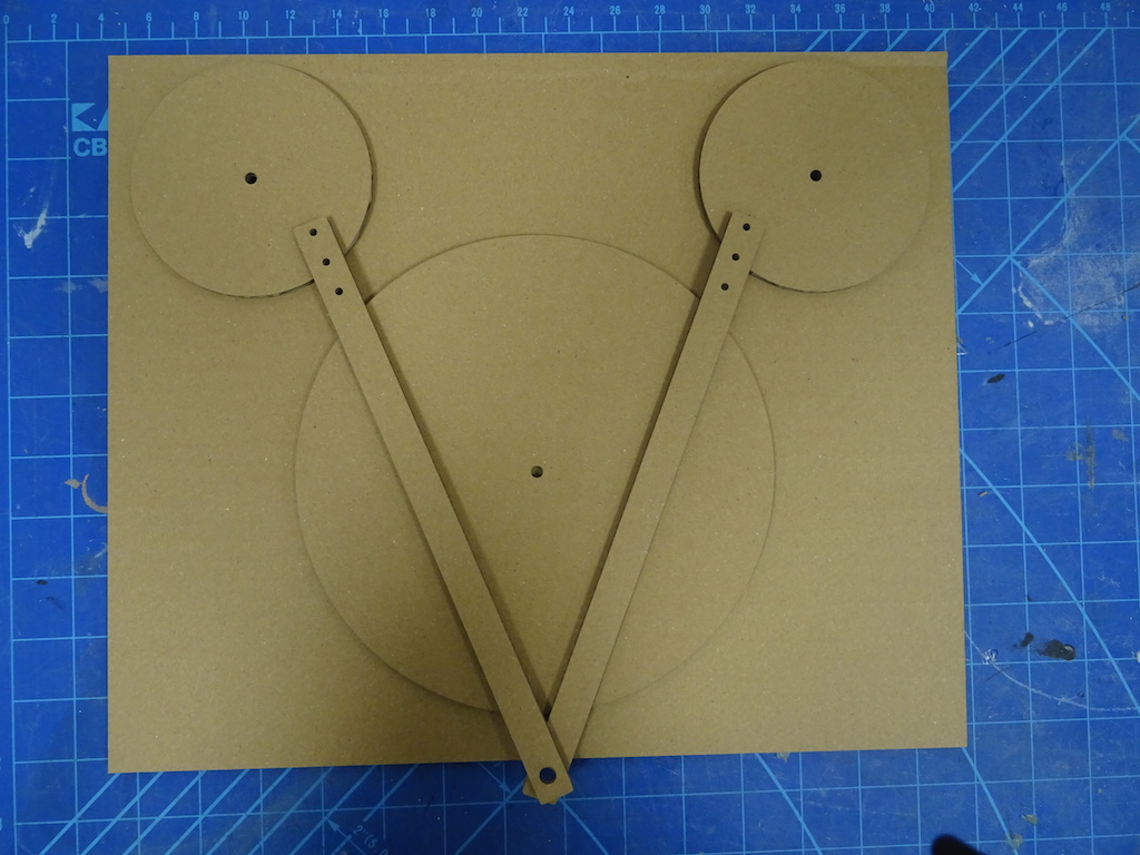
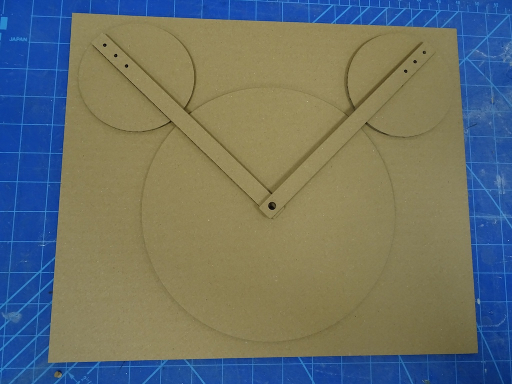
The arms extend beyond the disc where the paper would sit when the smaller discs are at their lowest point. The pen will sit in the large circle where the two arms meet. Change arm length. Then I also look at the relationships between the discs and the base - the borders. I adjust where the three holes are on the base.
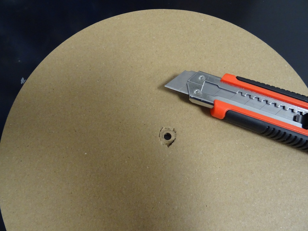
Now I need some pins to attach the arms to the small discs so I can simulate how the arms will move. The discs are supposed to move at different speeds. The arms are shorter, but I'm not sure how to determine the relationship among the arms and moving discs. This will be Charlie's task, but having this prototype helps me see how the thing will work. I find some small screws and 'countersink' them into the cardboard by hacking with a utility knife.
I cannot operate all the discs since I only have two hands, not three, but this starts to give me the idea of how it will go.
Now I have three stepper motors but no Gestalt node boards. I ask Solomon if he can order them from Jean-Luc and if they will arrive in time. (They hadn't been ordered earlier because I don't have a local instructor and the mails about ordering were not going to Solomon.) (No answer yet - maybe on Monday.) If not, then I will have to make the boards.
Charlie recommends that I do the milling of the Fabnet USB boards and catch up on the electronics lessons and assignments from previous weeks. Good idea.
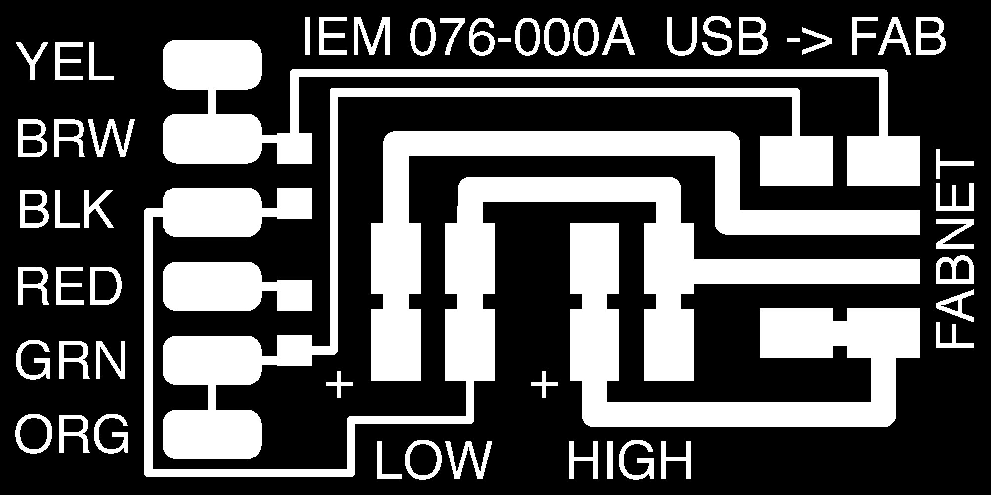
I started off with checking this page and getting the traces file from there. (Later I checked through all kinds of Machines that Make and Fab Academy machines assignment pages to see what others have done.) There is no outline file, so I think I'm doing the smart thing by copy pasting the FabISP outline, rotating it in Illustrator and fitting it to the size of the Fabnet board - exporting it as a png. See file below.
As there were so many problems with the Modela last week, we take the spoilboard completely off and instead use another PCB board as the spoilboard. Niklas says the chunk feels loose. Every time we go to change the endmill, the allen wrench gets completely stuck in the screw - so tightly stuck that we cannot get the wrench out without near violence.
Then when it comes to the traces, I did not change the artboard size so we have to adjust the x and y values to try to centre the outline on top of the traces. When we open the outline file, it is "soft" and there is an extra cutting line that must have come in during the Illustrator process. (I either forgot to take a screenshot or it is on some memory stick somewhere.) The first image file is the one in the tutorial and the second one is my wonky outline. Niklas says, do it in Photoshop. There is no drawing program on this computer (the one that talks to the Modela) so just to keep pushing on, we continue.

We do end up with two boards. One is relatively clean; the other is not. Niklas shows it to Solomon and says something like, it seems to be skipping steps on the z. They both also wonder about how flat the bed is - it seems to cut at different depths.
In order to speed up the new milling job, Niklas opens the traces file in Photoshop and changes the canvas size in order to accommodate both outlines and two traces so it will mill side by side.
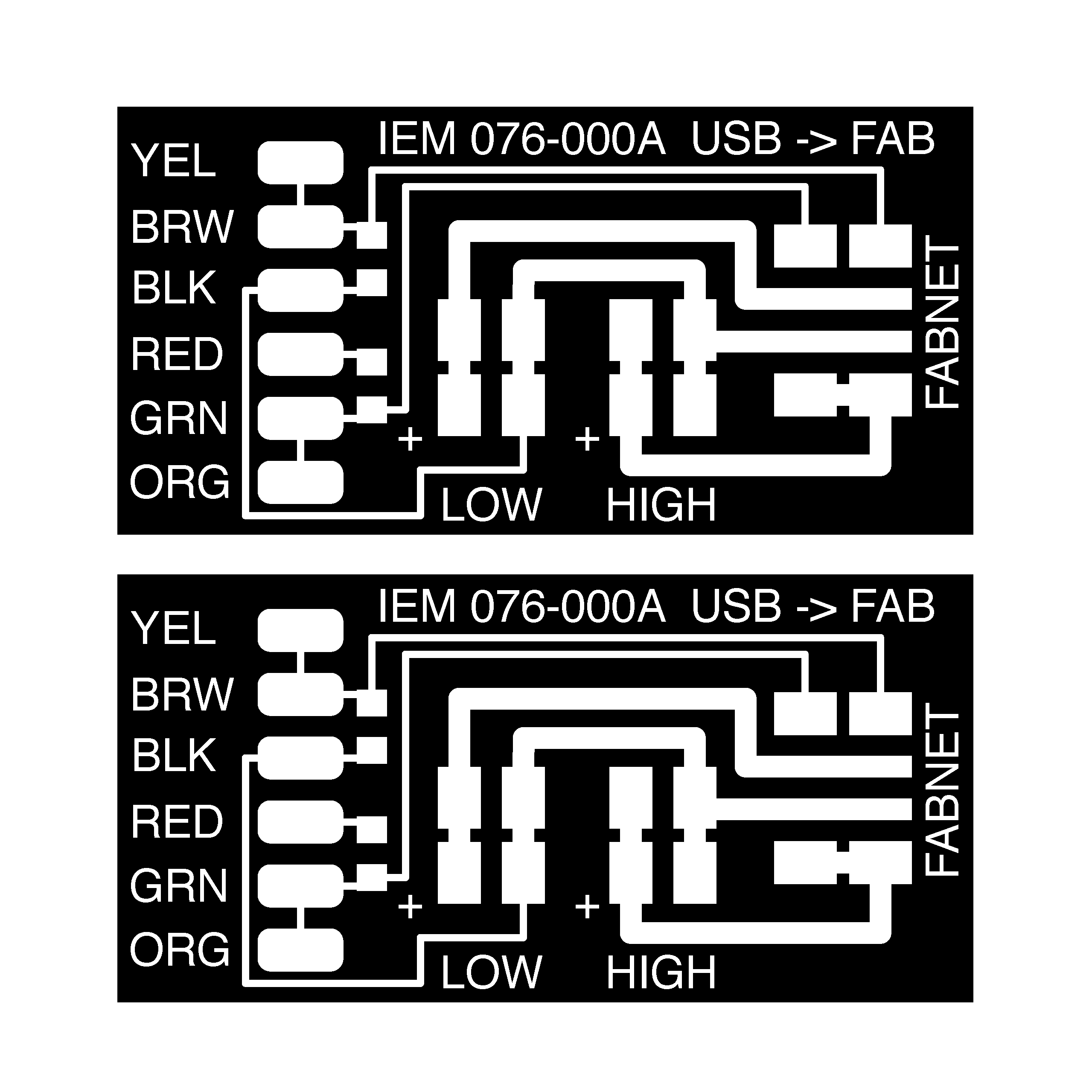
Then he creates an outline file on another Photoshop layer and I save each layer as a separate png. I will do this myself later when I make my own board.

Even after this little task, we decide not to mill new boards and to use the not-so-great boards anyway, just to save time. Niklas suggests using a pin connector from a cable in order to keep the two 4-pin headers in the right position while soldering.
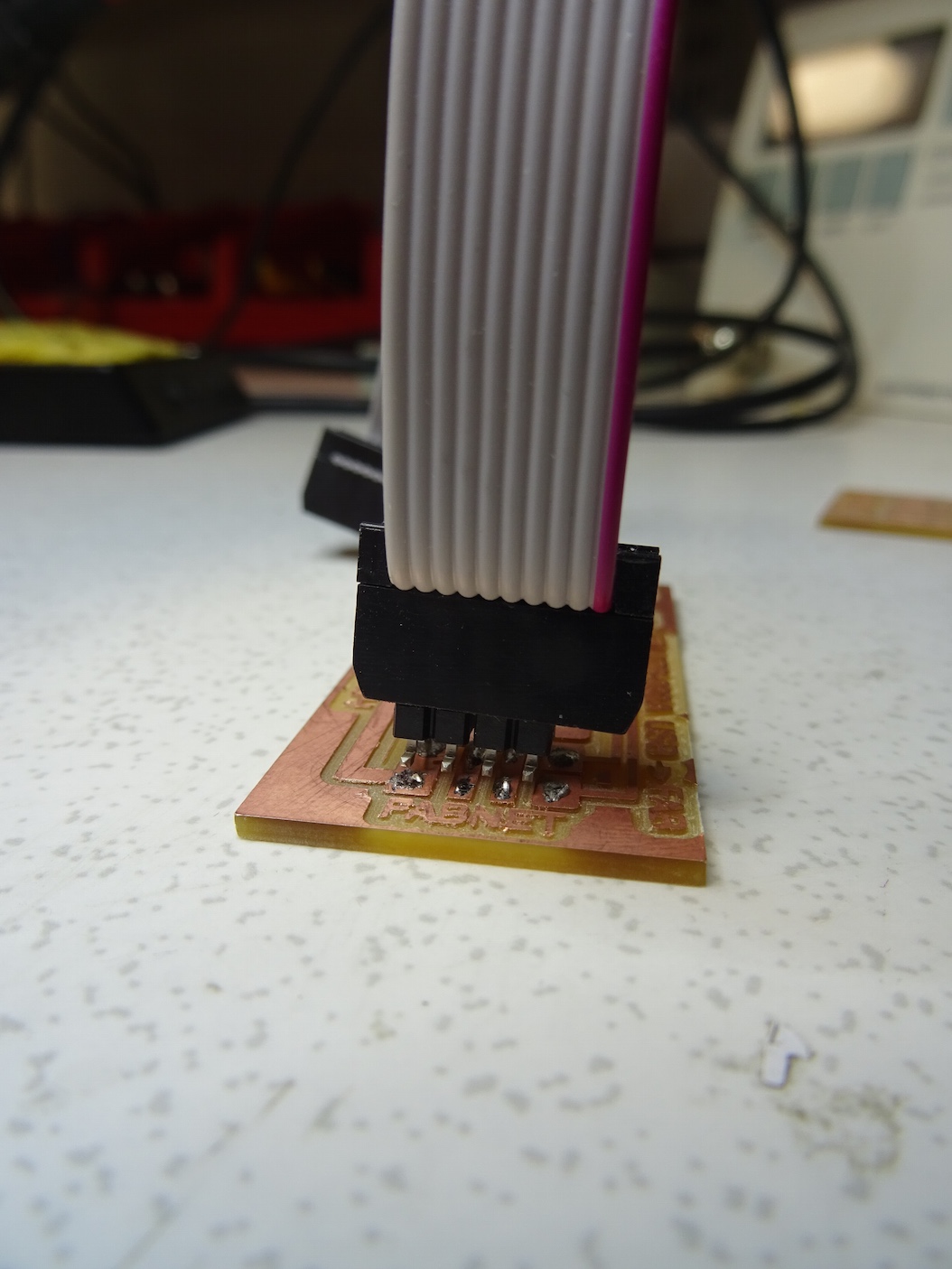
I do both headers for the 'Fabnet' and then the headers for the two power supplies. The FTDI cable I have has a pin connector on its end that we don't want to break off, so I take the six colours of wires and solder them on.
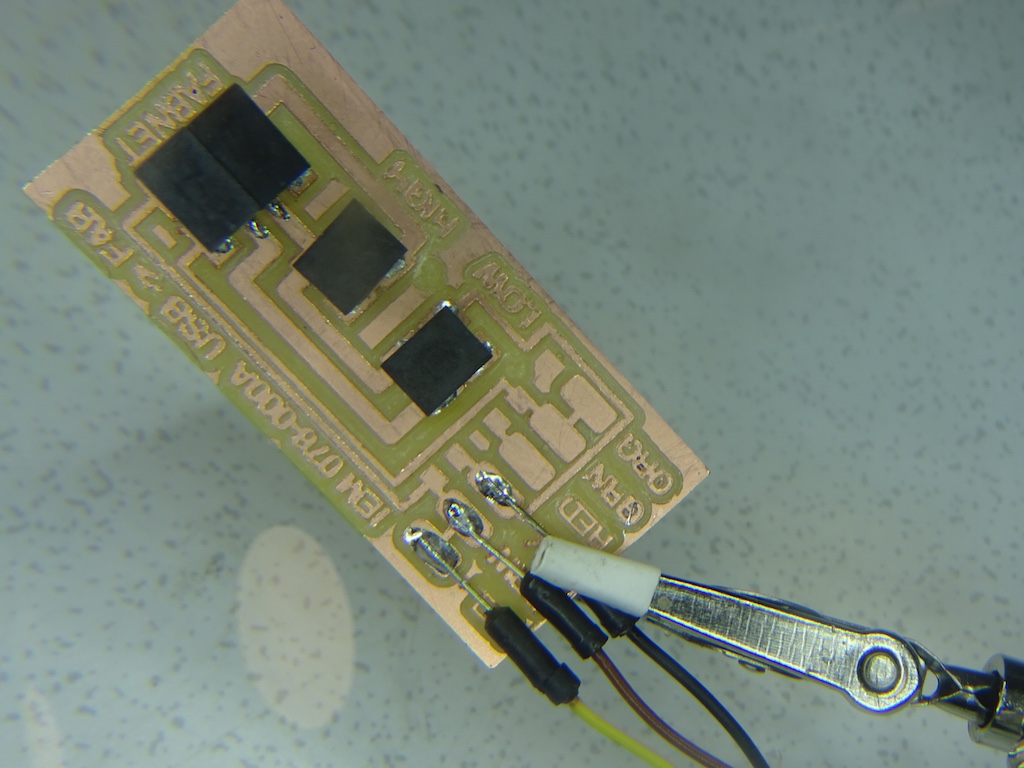
They seem fragile. I might need more solder but also maybe some kind of protectory-covery-thingy. I cannot put the resistors on now (none in stock). Solomon had told me to google the FTDI cable but I didn't know what I was supposed to be looking for. Later I find this 2015 tutorial and I realize that I had better check the cable too in order to check the wiring.
I haven't even begun with any programming yet, and I'm often feeling overwhelmed. Of course this comes from not having done the previous weeks' assignments in order and carefully, with lots of background research at each step. Even then - I often feel over my head.
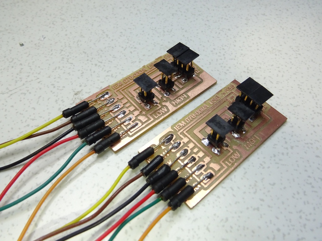
I check a few local workshops on this campus but they have so few surface-mount resistors and not the ones I'm looking for. Charlie suggests the obvious, which is just to use through-hole ones. argh
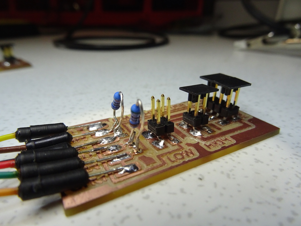
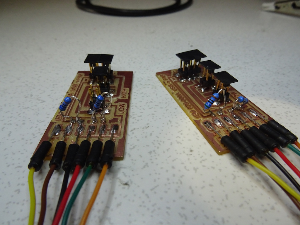
So the Fabnet gets packed away carefully and flies off to the UK. There was a piece of packing foam from something that had been delivered here; it seems it will protect the sticky-uppy resistors. And weirdly it's exactly the same width as the cardboard box I'd brought from home. We love re-use and recycling.
I do a bit of DIY service design on the package so Charlie can get the coffin back out of the grave-pit, as it were. He asks for an 8-pin connector, but we don't have any in the lab so we will both have to find those elsewhere.
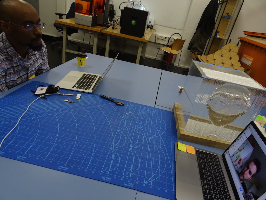
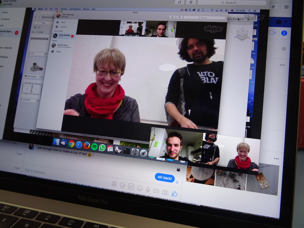
We try to keep each other updated by email and by Skype. It's a challenge to be working on one machine that is to be in one physical location. For my own learning I will make my own version here that might (or might not) be 'networked'. For Charlie's machine, Charlie, Niklas and I will check the programming of the gestalt nodes over Skype once the Fabnet has arrived.
I have my own stepper motors and drivers here and would still like to make a version of the drawing machine here, which means making or getting my own board of some sort (to replace the Gestalt nodes I don't have).
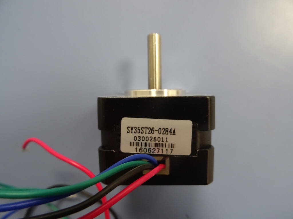
The stepper motors are these ones, www.pololu.com/product/1207, specifications;
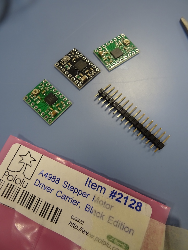
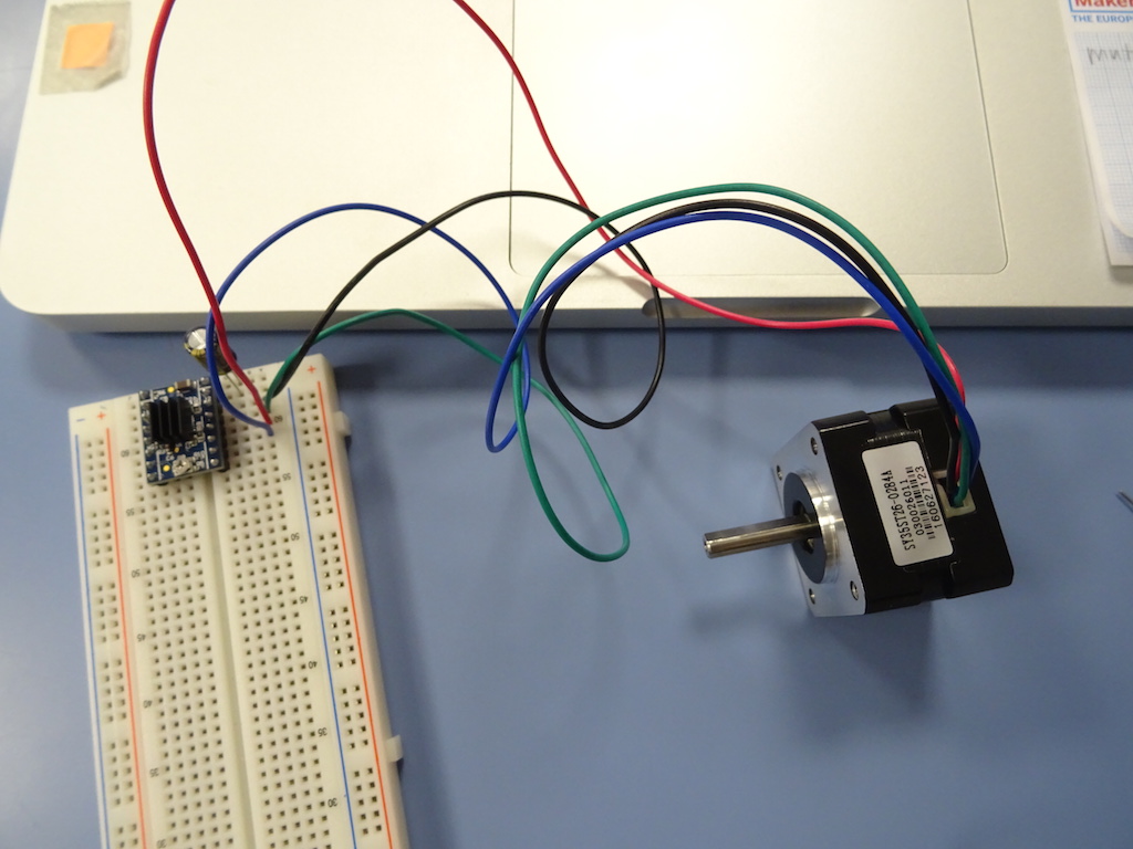
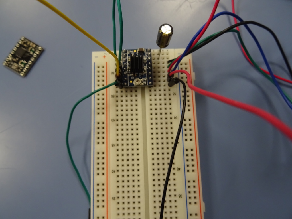
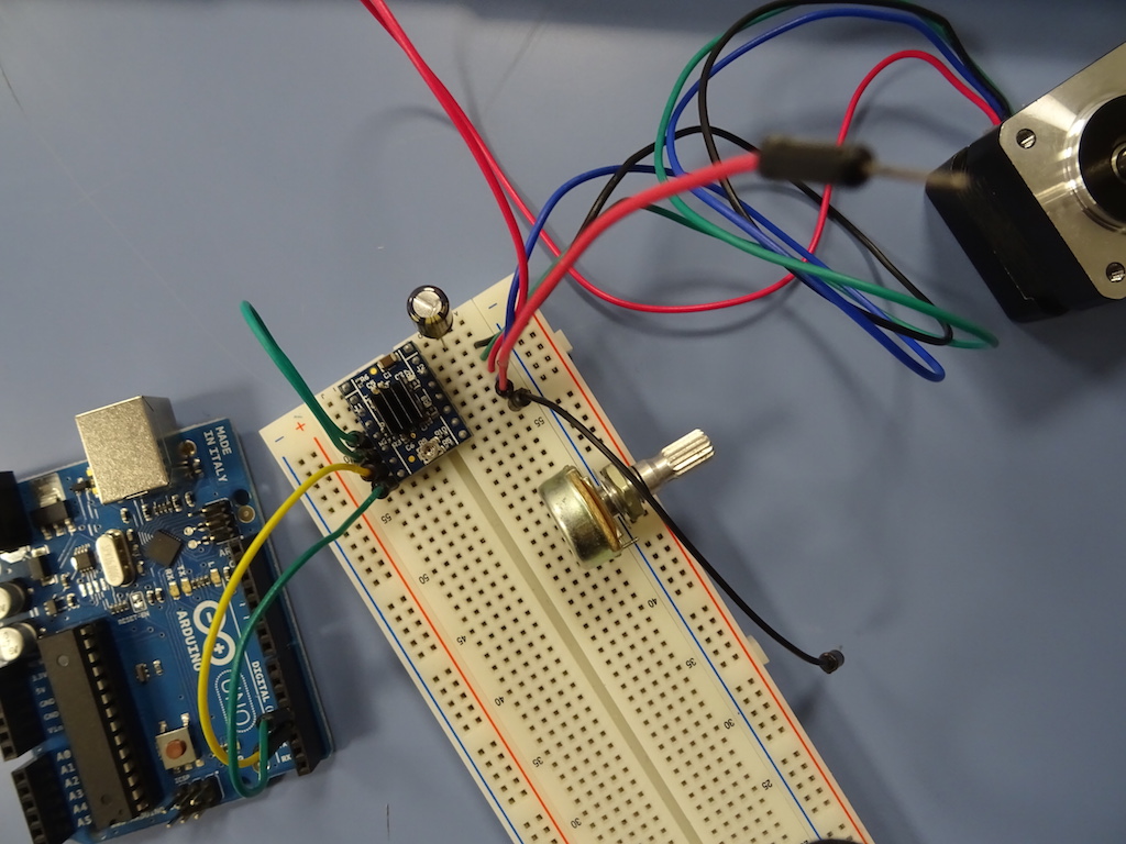
the drivers are these A4988s: I have two green ones, www.pololu.com/product/1182 and one black one www.pololu.com/product/2128. I start by learning how to connect the driver and the motor on a prototyping board. Because I'm a beginner Niklas suggests we try connecting everything and using an Arduino as the microcontroller, just so I can see how it works and how the motors will turn. This tutorial explains there is a 47 µF 'decoupling capacitor' needed to protect the board from 'voltage spikes'. Screenshots below.
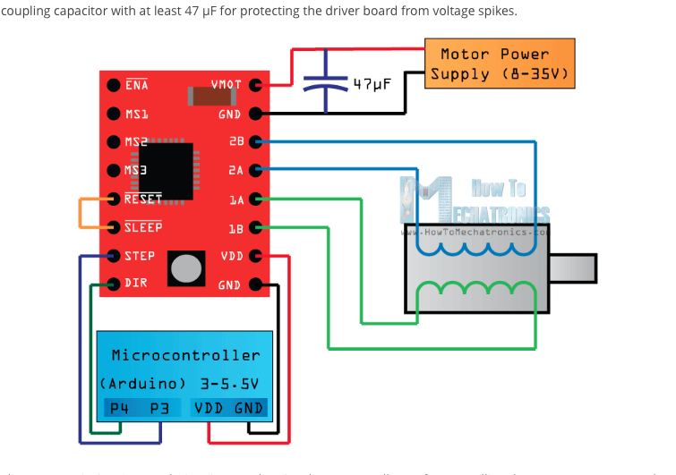

We start connecting everything. The tutorial says to connect the RESET pin to the SLEEP pin. We will also do this test in full step mode so I don't connect anything to MS1, MS2, MS3 pins.
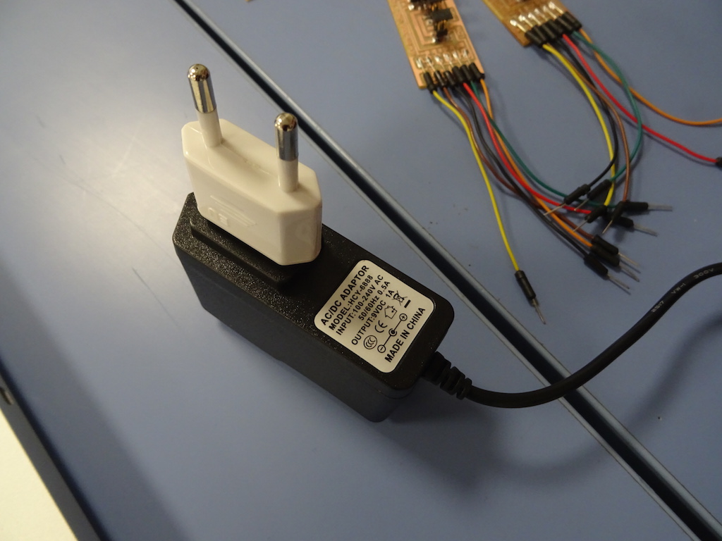
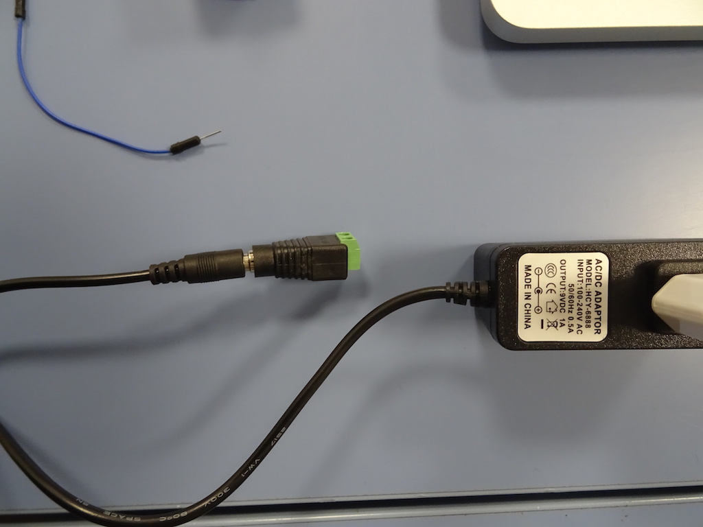
We look for a power supply and find something that seems to fit. The stepper motor data says 7.4 V min, amps 280 mA. Niklas says it should have more voltage and more amps to drive more motors, but it will do for now.
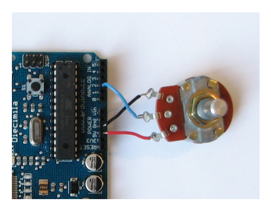
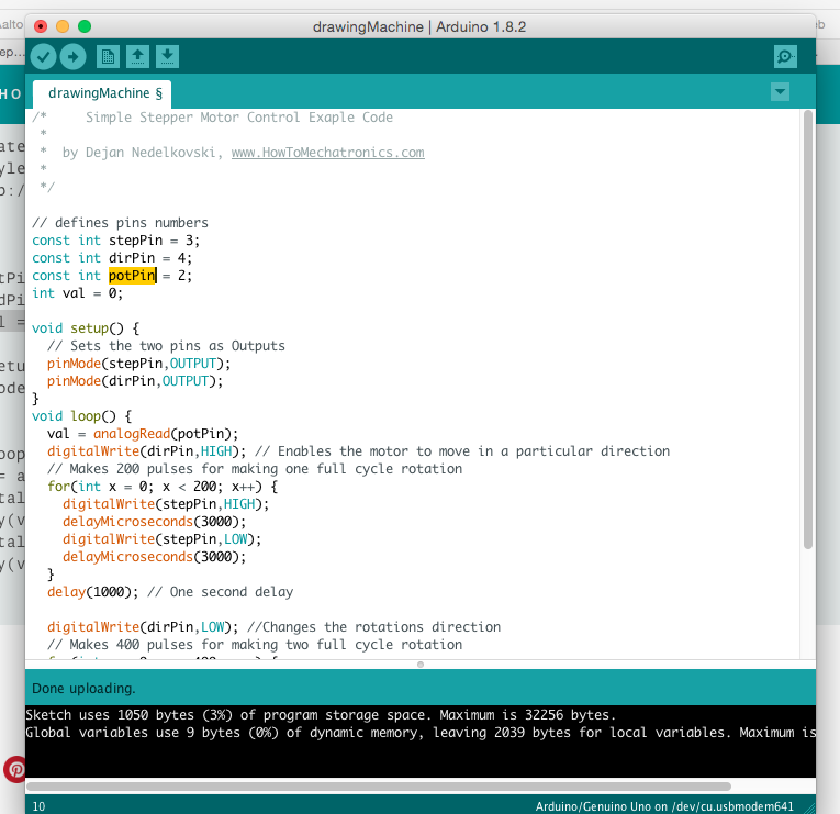
Niklas suggests using a potentiometer to control the speed of each disc manually. There would be no need for a computer with this simple machine. We could hook up a potentiometer and I could see how it works. It's an appealing idea. We find this tutorial and we connect a 10K potentiometer to the board, and everything to the Arduino.
screenshot from tutorial
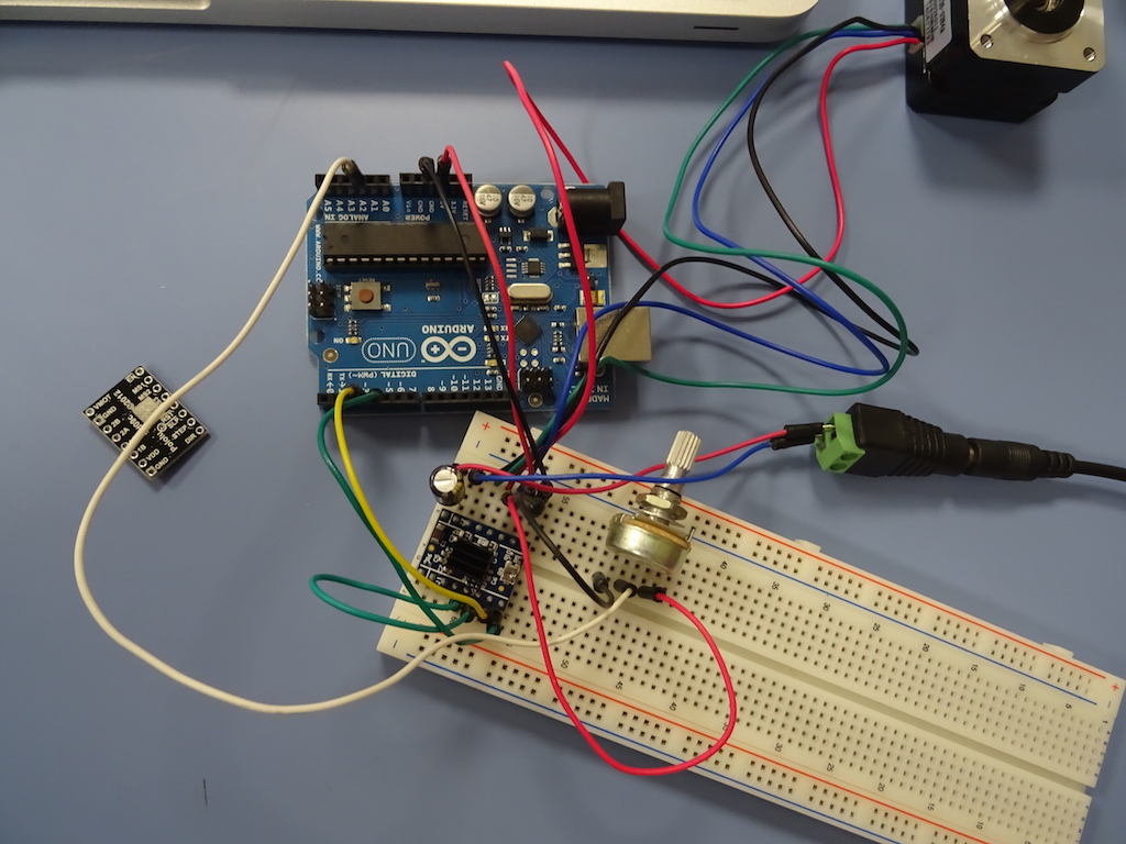
We disconnect the power and ground from the Arduino so we don't blow it and plug it in to the computer. I open the Arduino program, open a new file and save this as a new file. We check the example code from the Mechatronics tutorial and just copy paste. Press the arrow and it will start compiling and upload the code. Don't forget to go to Tools -> Board and choose Geniuno/Uno, and Tools -> Port and choose the USB.
We plug in the power without touching anything (!) and nothing happens. We unplug the Arduino and remove the power and ground wires from it. We suspect the power supply and choose another one. It's difficult to find one, as the cables ended up in a few places after the lab moved here; it's so busy that no one has had time to really go back through boxes and drawers and put things in their proper places. Power and ground back into the Arduino, plug it into the laptop, plug in the power - and it works!
to be continued. Niklas makes some adjustments to the code. notes to self - see notes of 20.04 on coding. soldering the drivers / pins. then the full board with 3 motors, 3 drivers, 3 potentiometers. and a video.
Fab Academy goals:
Work and communicate effectively in a team and independently.
Design, plan and build a system.
Analyse and solve technical problems.
Recognise opportunities for improvement in the design.
Cindy's goals: (a) Make a machine in a way that I can also catch up on previous assignments. In progress. It is a lot slower than I thought it would be: can I do the machine at the same time as the assignments? Can I replace some exercises with machine boards? To be determined.
(b) Make a machine with a colleague in another country without a local tutor. In progress. We communicate by Skype and email and it goes well. Being both physically here or there to test and make would obviously be much easier. And I am getting good help from a part-timer in the lab.
(c) Make a machine that is nice looking, works and within my beginner capabilities. In progress.
Notes and reflections to come.
Notes and reflections to come.