Once upon a time, in a former life, I was coaching a person in English written communications. She was working for a regional development authority and had to do all kinds of reports and slideshows in English - so I was helping her. We were working on a document in Word - she had it up on the big screen. Every time she made a change and wanted to save the document, she moved the mouse to File at the top of the interface, clicked on Save As, and saved the document with the same name. She obviously had never learned the Ctrl-S shortcut. It drove me a little batty, but I didn't say anything.
Now the shoe is on the other foot. I'm so slow at using Eagle that I can imagine Niklas is just tearing his hair out when he watches me. He doesn't use Eagle much himself, but he just knows enough that he picks up the shortcuts fast and can just use the software at ten times my speed. Faster. Then I can't find the right component, with the right labels, the right size - I have to search for it because making one would take even longer. Then I don't know what exactly needs to be connected to what and why. What would take someone else an afternoon has taken me two days. Over and over in my notes I have written, 'This is not fun.' Neil says several times in the lecture not to get overwhelmed, but every day I feel overwhelmed.
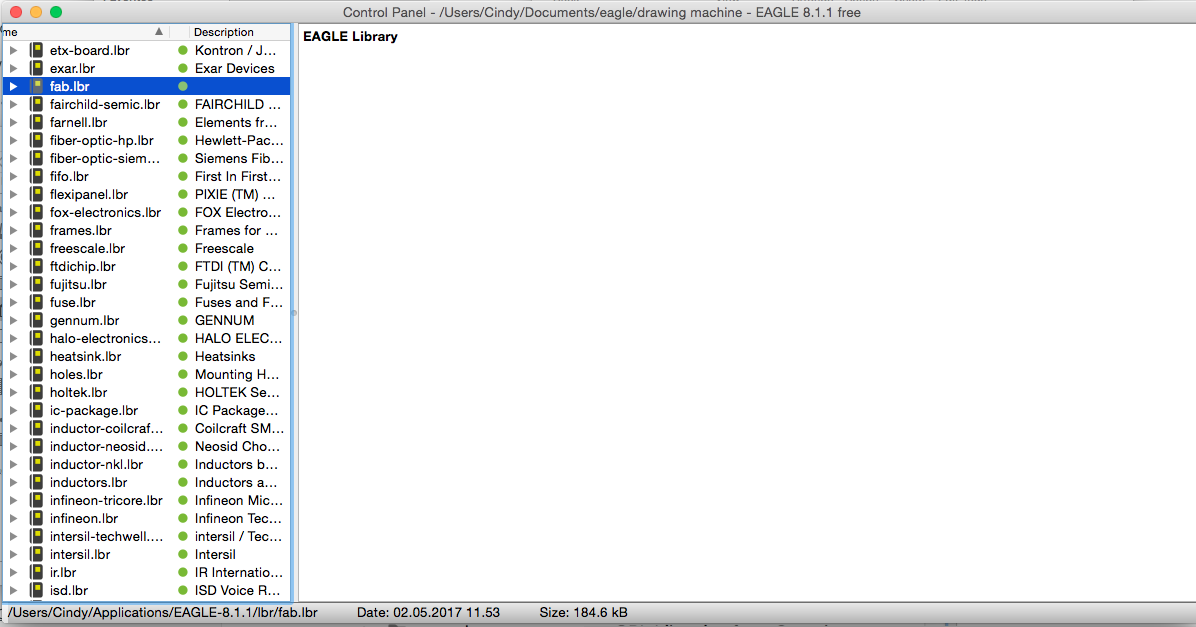
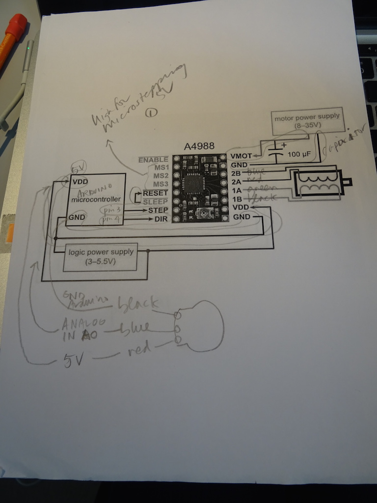
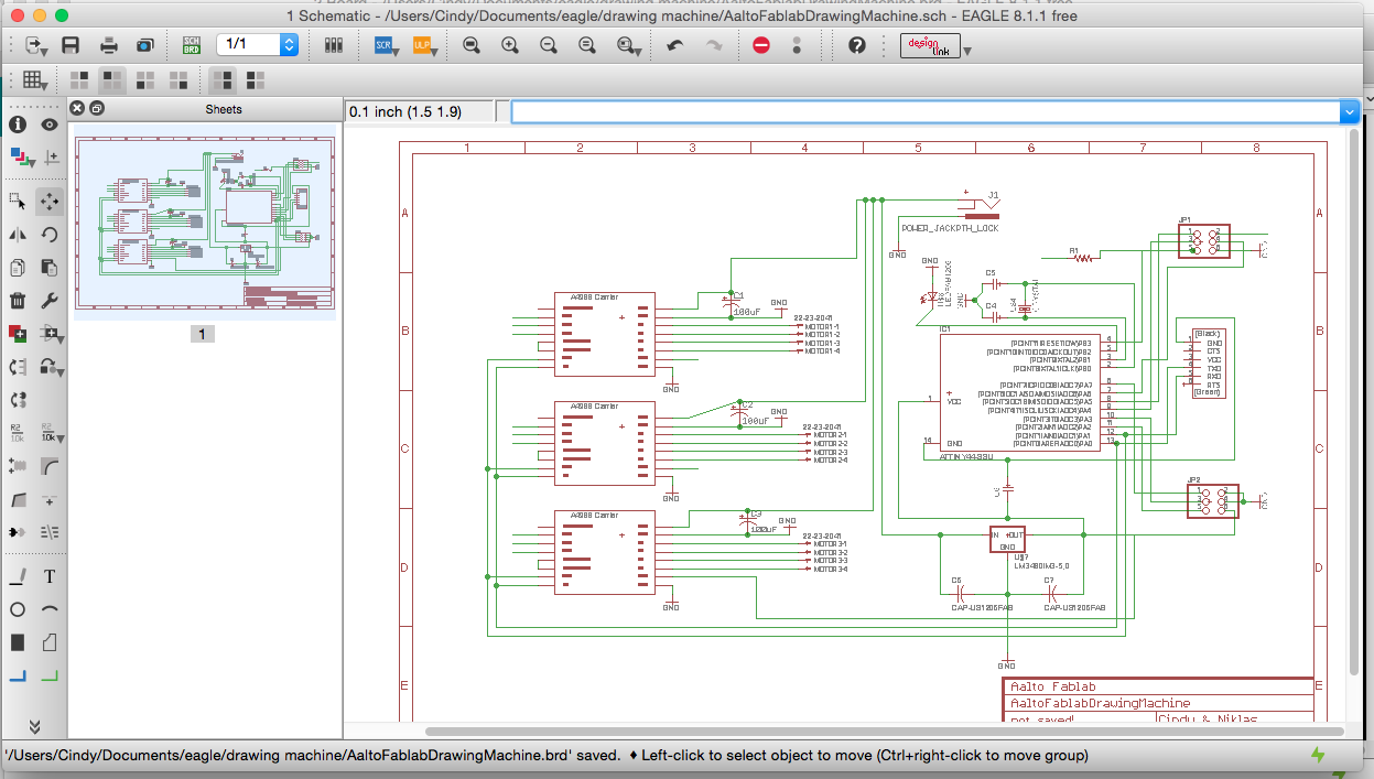
But back to what I'm doing. Since I have to do a separate board if I want my machine to work, I combine this week's assignment with my stepper motor board. (note to self - put in link to the machine page.) We got the motors to work with the potentiometers and an Arduino, so my intention is to draw that up. I download Eagle and go through Sparkfun tutorials (here and here) and the Fab Academy tutorials. The Fab Academy tutorials are all worded in a way that there is some existing schematic for the echo board to start with - but all the links are dead. Wendy tells me that we should start from scratch - that is the idea. OK. I get the fab library and add it - and cmd-click the dot to 'Use' the library (turning it from grey to green).
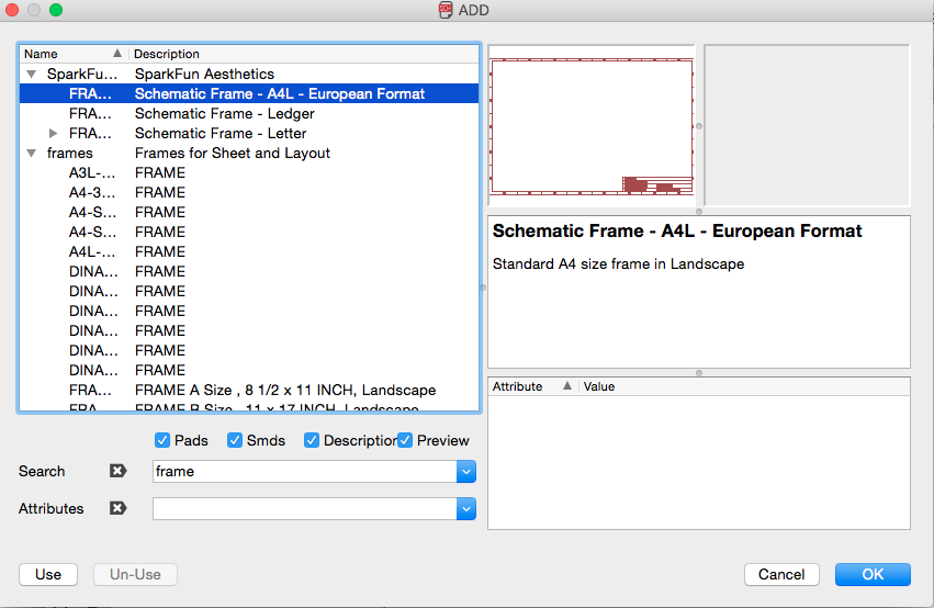
I decide I want a frame for my schematic so use one from Sparkfun.
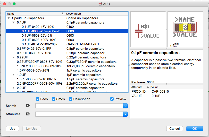
Then I just try to find the components, which takes hours. Or too long. If I can't find the component then I try to find an existing file or library. And what size? Good grief, there is the size too. What components are the ones we have? Go back to the component tower. What are the standards? I don't know. Can't I just put something here and hope for the best? What a mess.
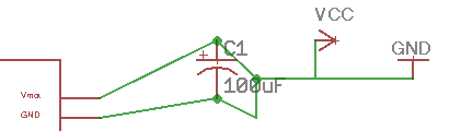
Connect up the stepper motor driver. Use 'net' instead of 'line' as the tutorials say. Hit the little circles at each end of the capacitor. Wait a minute - I shouldn't draw the lines like that because it makes connections to the lines - not the capacitor.
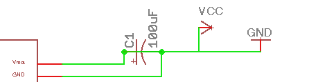
When I move them I see they are connected and shouldn't be. I also click on Show in the top right of the toolbox to see what is connected. And of course power needs to be coming in and not out. Let's fix that later. This is so slow. I'm so slow. I need a drink but it's the middle of the day.
So now I have the drivers and motors connected, with the power going the wrong way, and I would like to label which colour wires of my particular motors go to which pins. How can I do that? Let's put the Arduino there. Niklas suggests making another small board for the potentiometers, so one ribbon cable will go from the driver board to the potentiometer board - which will connect all three potentiometers. I will need a header for that cable.
Then Bas suggests that I have to do the assignments anyway, so I could rather make a board (the echo board) to which I can add my motors and potentiometers. Argh. I don't know if I can do this. Niklas and I check the ATTiny23, but it only has 2 analog input pins and we need 3 (because I want to use 3 potentiometers for controlling the speed of the motors). The Tiny45 has enough inputs but it has only 2 output pins instead of 3 (3 motors). The ATMega328-PU seems to be the right one, but it cannot be milled: the traces are too small for the milling machine. I don't think I will be able to solder at that level. And then I would have to learn etching. I would really really really like to finish this damn machine before October. I also have other assignments not done - not to mention my Real Job. I would really just like to get the machine done using Arduino and do the assignments separately - or for my final project. But Niklas argues, to be helpful, that then I would have the board design for the mega. I am not sure what I need for my final project - is it a mega? How should I know? How much longer do I have to do Fab Academy before I know? I'm so confused. The Fablab is out of ATTiny44s - we hope they have been ordered from another workshop - because it would work (enough pins) and it is also the one on the echo hello board. Hooray! Yes, the other workshop has ordered some in.
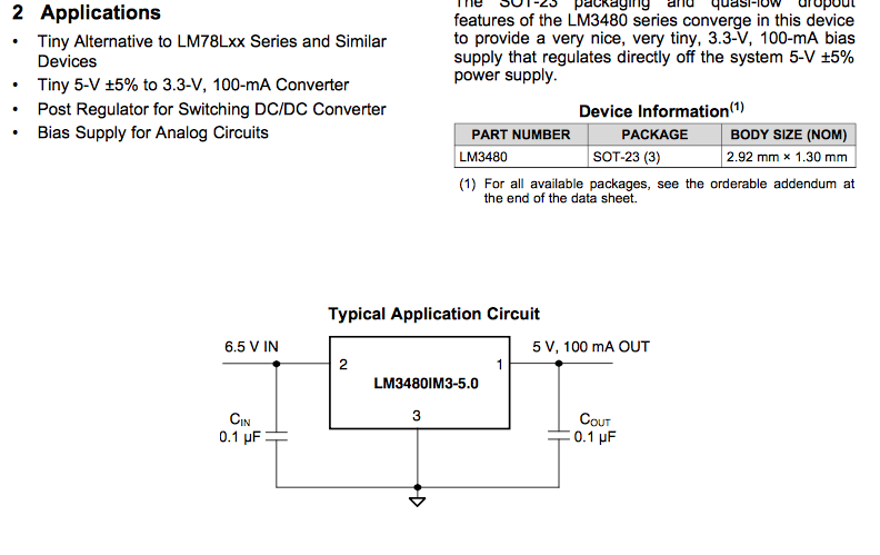
So change of strategy. Add the FTDI header, the header for the cable to the potentiometers, the header for the programmer and its resistor, the LED and its resistor, the crystal and its capacitors. Niklas recommends a 12V voltage regulator that we have here. He says its package size is SOT23-3 (how far away the legs are from each other). It needs two capacitors of 0.1. Can we find the component in the existing library? The datasheet is here). It should be connected like this:
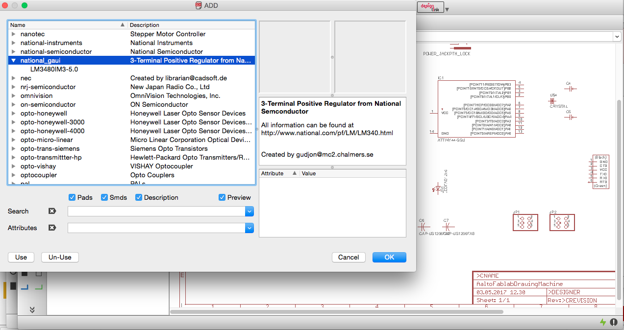
After looking and looking I find the LM3480 Eagle library file here). I download it and put it in the library folder (Cindy/Applications/Eagle-8.1.1/lbr). In the Control Panel view, View -> Refresh. Click open the Libraries and click (or command click, Mac, clicking on Use) on the new library to turn the grey dot to green. Click on Add in the Schematic view and find the part to add it.
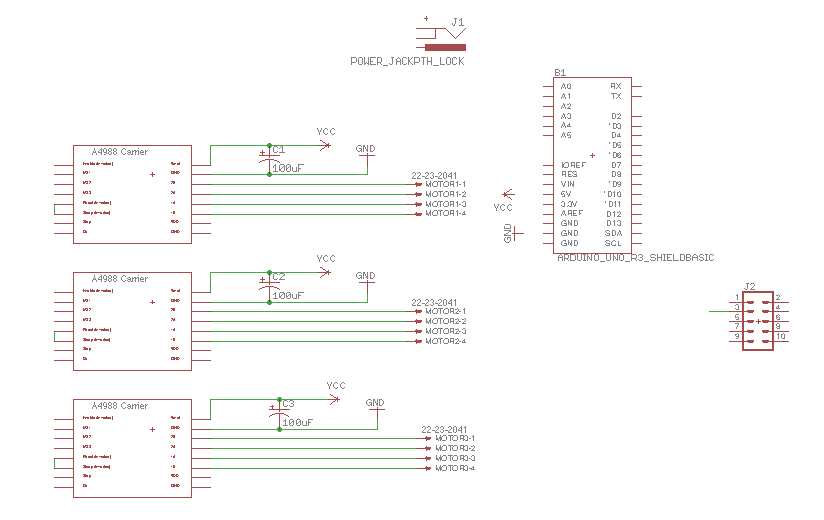
The drivers: RESET and SLEEP are connected to each other. I don't remember anymore why. STEP and DIR: on the Arduino they were connected to pin 3 and pin 4 - where now? If it turns only in one direction then we could have the DIR high (or low) all the time. This is fine. For this drawing machine, it doesn't need to change directions.
DIR - high - one direction, low - the other direction. DIR pin is high - always 5V. STEP is getting pulses which moves it forward. high to low. I'm just writing this down while my brain is lagging behind. When Niklas or any Fab Academy instructor says anything, I hear askfweogdfk serial vdeowfnfgkjs wlei kkefjw resistor evrwekfksdjf weoriwekf step ergkejfkr e ritoerj platform. Very little makes sense. Sometimes it does - later - but I would rather this were less complicated now because I feel like I'm doing a degree in electronics in only two weeks. OK, concentrate. Connect driver STEP to Tiny pin 12; DIR to pin 13. The power supply will supply 12V power to VMOT via the 100 UF capacitor and ground to ground. VDD needs to be connected to 5V and GND to GND. At some point we label the 5V net, which I explain below.
When we did the testing with the breadboard, full step mode was too fast so we changed to microstepping. (note to self: put in the link to the documentation on the other assignment.) This means that pins MS1, MS2 and MS3 should be connected to 5V. The stepper motors can be connected to a four-pin header, which I have renamed MOTOR1, MOTOR2 and MOTOR3. Pin 2B to the blue wire, 2A to red, 1A to green, 1B to black. I find it much easier to keep track (or not) of these things with traditional paper and pencil.
And the FTDI header. God, this is taking forever. I'm starving to death and withering away from lack of liquids. Niklas must be frustrated because I'm so slow with the software and with understanding this. I find this drawing by Yado Sharon which helps clarify to me what should be connected to what. GND to GND on the Tiny. Niklas says don't connect CTS. He's not sure if we need to connect VCC - the Tiny is already powered from the power supply, right? We're not sure. We leave it unconnected. TXC to PAO and RXD to PA1. RTS to nothing.
And the programming header. In Yado's diagram and the Fab Academy tutorial, pin 6 to GND. pin 4 MOSI to PA6. pin 2 to 5V. pin 5 to a resistor and PB3. pin 3 SCK to PA4. pin 1 MISO to PA5. Now I'm getting a bit lost again.
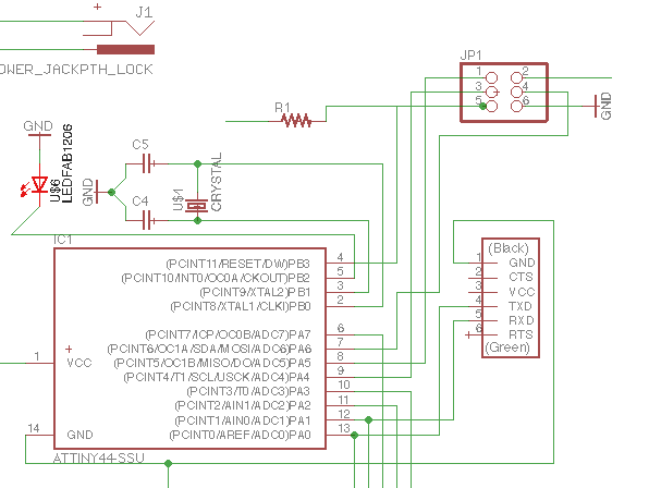
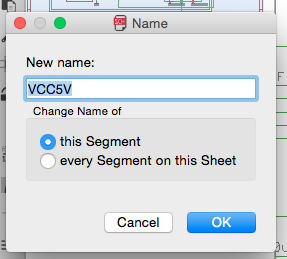
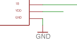
The crystal and capacitors to PB0 and PB1. The regulator and its capacitors. Actually I'm probably out of order here, as I probably connected these earlier. (Neil is right, document as you work because you lose a lot when you try to do a few days later.) From the power supply 12V to the regulator - which will then have 5V coming out. We name the networks to separate the 12V from the 5V. Click on Name and then click on the line: rename all the 5V lines as 5V. Then when there is a line (net) coming from a pin, such as the driver VDD, rather than physically drawing the net-line and connected it, I just need to rename it VCC5V and it will be connected to that net.
Still??? That damn LED just so I can satisfy that damn assignment. I connect it to PB2 but now where is the resistor? Too tired. Check it later with Niklas. Finally, the header for the potentiometers. Each potentiometer has 3 wires. For the header, 2 and 4 to GND. pin 6 to 5V power. pin 5 to PA2. pin3 to PA3. pin 1 to PA6, the last one left. The pins connected to the FTDI header can double up with the driver connections, as they will not be used at the same time (PA0 and PA1). Now I have to remember these pins for when I draw up the potentiometer board.
That was exhausting. I haven't even begun with the traces yet. And I haven't labelled the values. This is useful - but there would be other assignments that would be more useful for me to be doing right now. Instructions and objectives to "understand the data sheet" and draw a circuit - it is not that simple. It is not something one can just pick up in a week or two. It is not just about designing something simple using the software - that I could do. But understanding all the elements that go into the circuit design, what resistors do I need? why? what diodes? what capacitors? where?
I really think the Fab Academy instructors massively underestimate the ability of beginners to take all this in. (And yes, I'm at a great disadvantage because I'm alone and I don't have a local tutor.) But I have been doing all kinds of tutorials and reading all kinds of things - I have been asking Niklas and Solomon and other people in the lab - and still I cannot absorb enough information to be able to accomplish this in one or even three weeks. It is very very very frustrating. And I have not been able to get to other assignments that I would find much more enjoyable because of this freaking machine assignment.
I do totally get why we are asked to do these assignments, on time, in order, and do understand what Arduino is without just blindly using an Arduino board, and that the assignments are simple and step by step. But really - they are not that simple. There really needs to be some flexibility in allowing people to do assignments at their level. I don't have the Gestalt boards here so I'm instead using an Arduino - and that is discouraged. I understand why, but then it took me two days to draw the board, not to mention draw the traces, mill the board, solder it, test it or program it. Is that going to take me another two weeks? Probably. So my struggle continues.
Notes and reflections to come.
Notes and reflections to come.