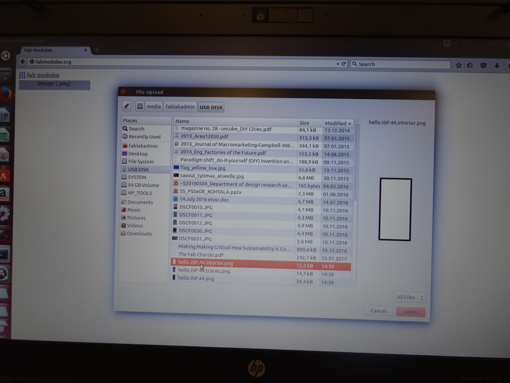
I have to catch up on this assignment, so I mill the Fabnet USB boards needed for the machine group project. (I do two - one for me and one for Charlie.) (Of course later I realize this is not the Fabnet but the FabISP.) This is the first time I'm using the Modela, so Niklas goes through it with me.
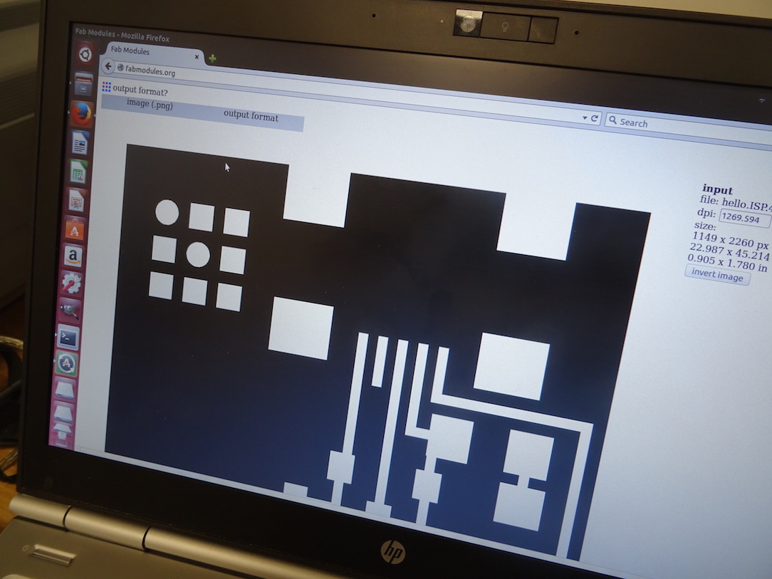
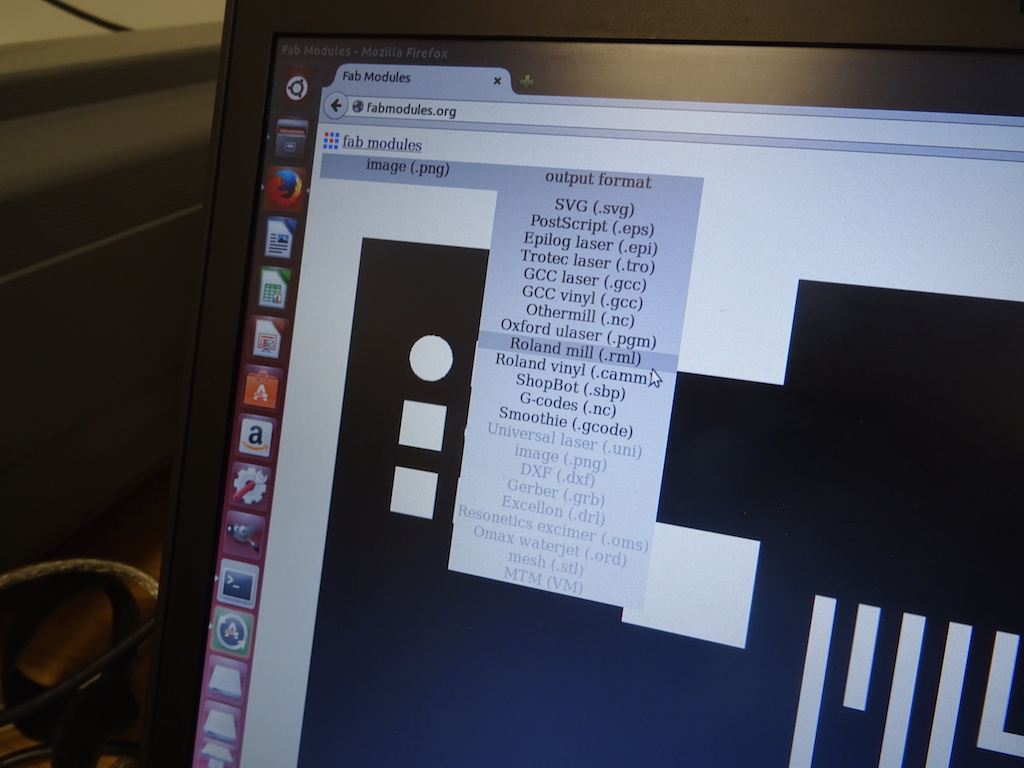
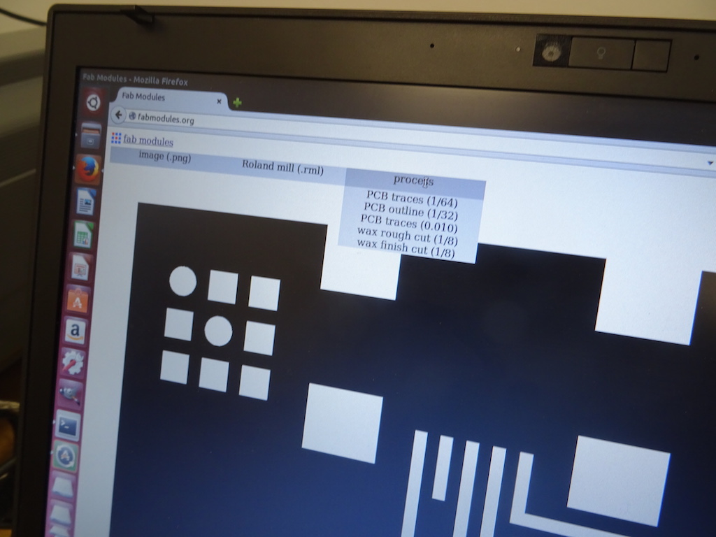
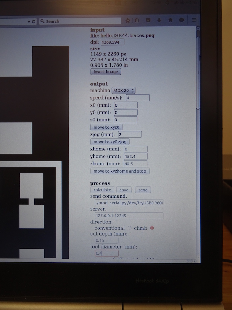
-choose which image, choose which output format (Roland mill), choose which process (PCB traces (1/64)).
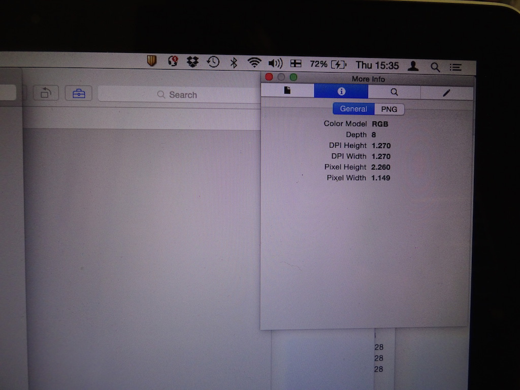
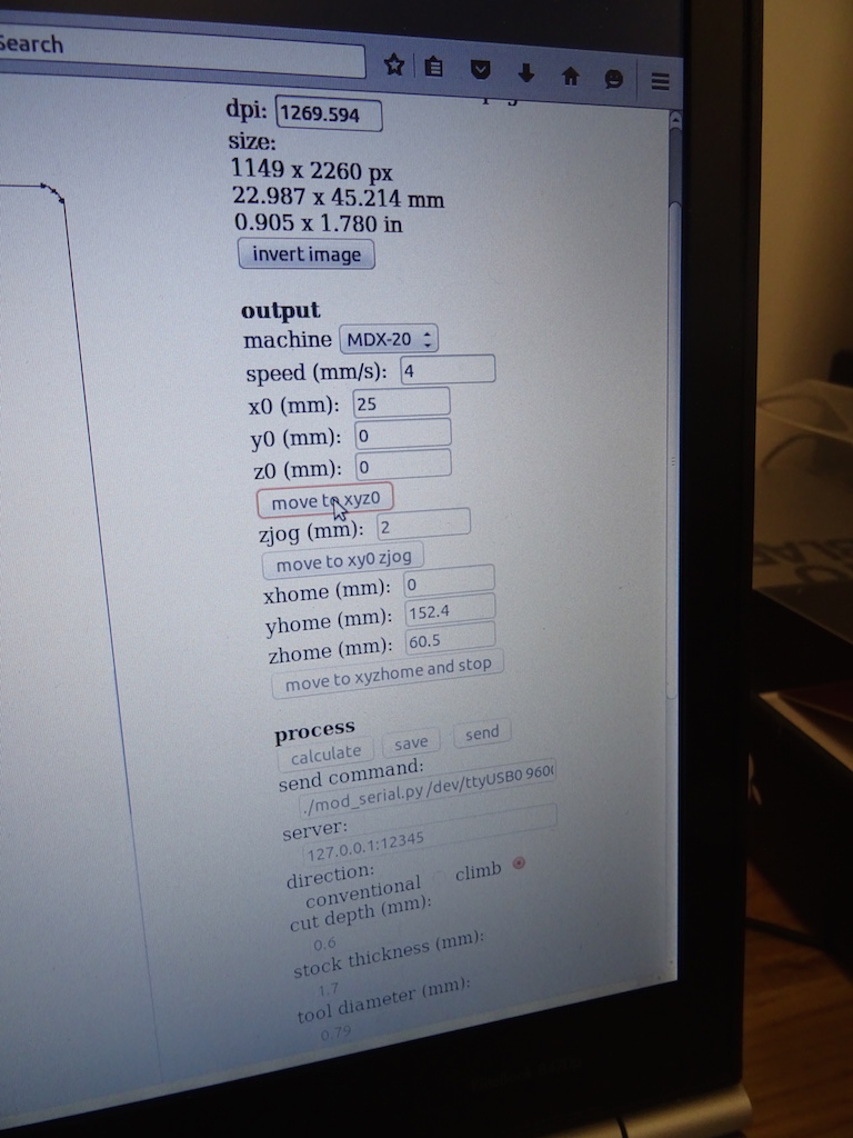
-check the DPI.
-choose the right machine.
-add ./ to the 'send command' field before 'mod_serial...'.
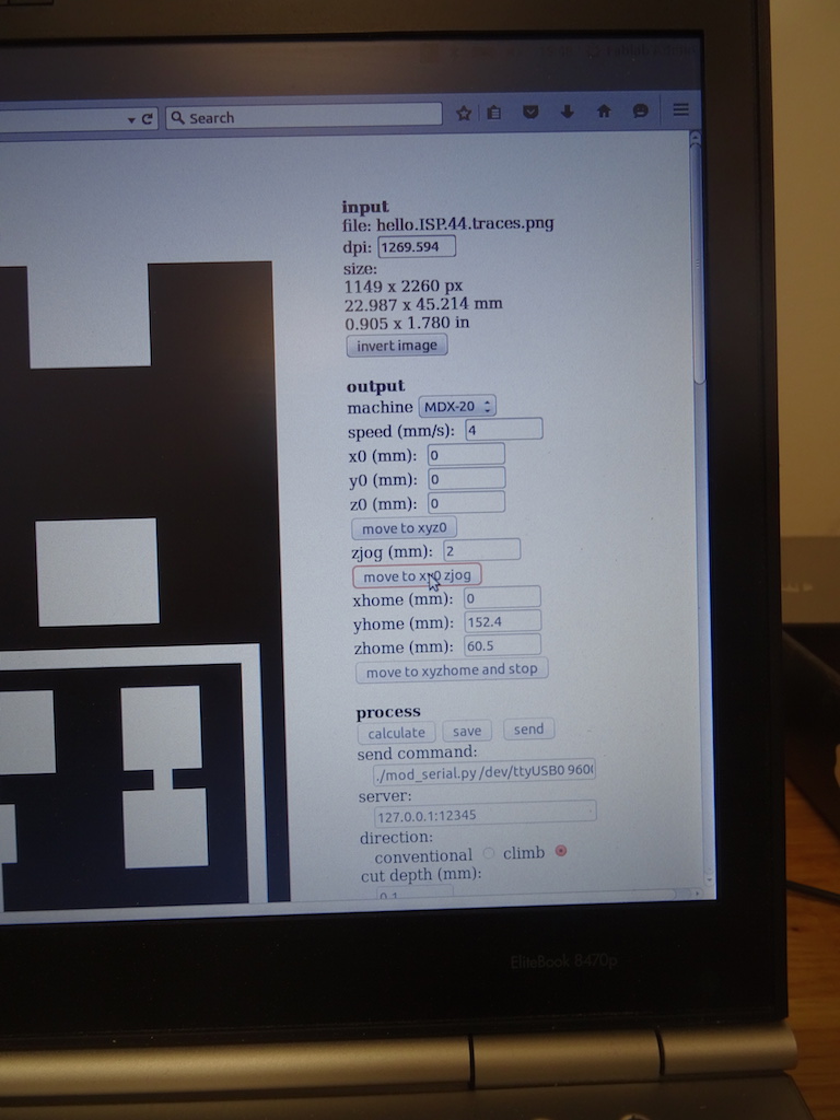
-test by pressing 'move to xyz0'.
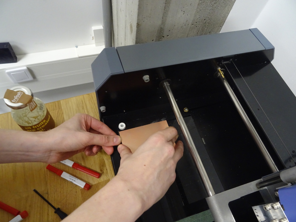
-put in a 1/64 bit, but not tight, and quite high up.
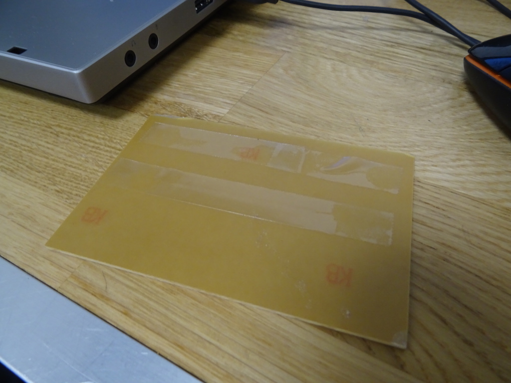
-tape the board to the spoilboard with double-sided tape. (make sure the spoilboard is there.) press the board down with something (not your fingers, to avoid fingerprints).
-press view.
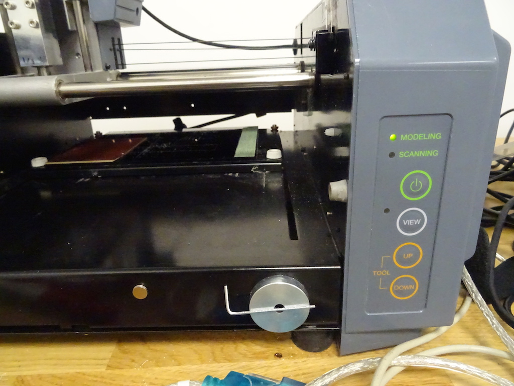
-set the height manually by dropping the bit to the surface and tightening it, on both sides. press view again. if you need to reset, press up and down at the same time for 10 seconds.
-the x setting should be 0, y=0, z=2.
-put the lid on.
-check the settings - the cut depth is now 0.1 mm. Niklas says this has not been cutting through so he recommends 0.15. the other settings are default and ok.
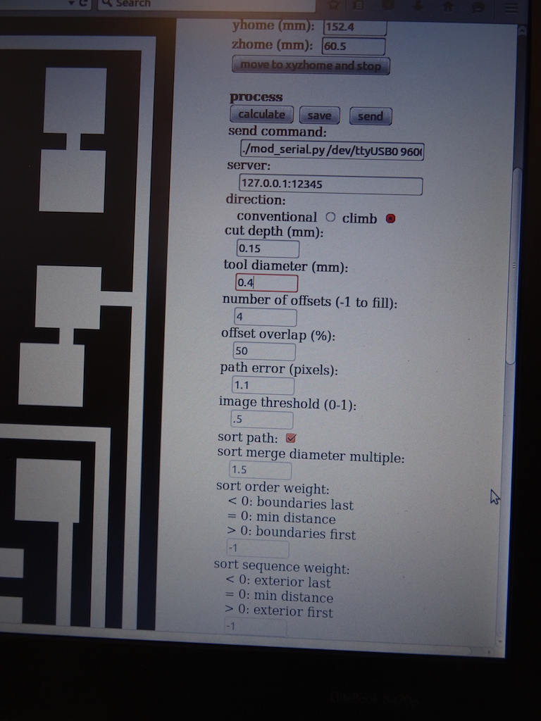
-press calculate - this shows what will be milled.
-press send.
-if there is too much dust collecting, hoover it out carefully.
-then change the bit to do the interior, 1/32.
-again, choose which image, choose the output format (Roland mill), choose the process (outline 1/32).
-check the DPI, choose the right machine. add ./ to the send command field at the beginning.
-press 'move to xy0 zjog' to check, check 'move to xyz0'.
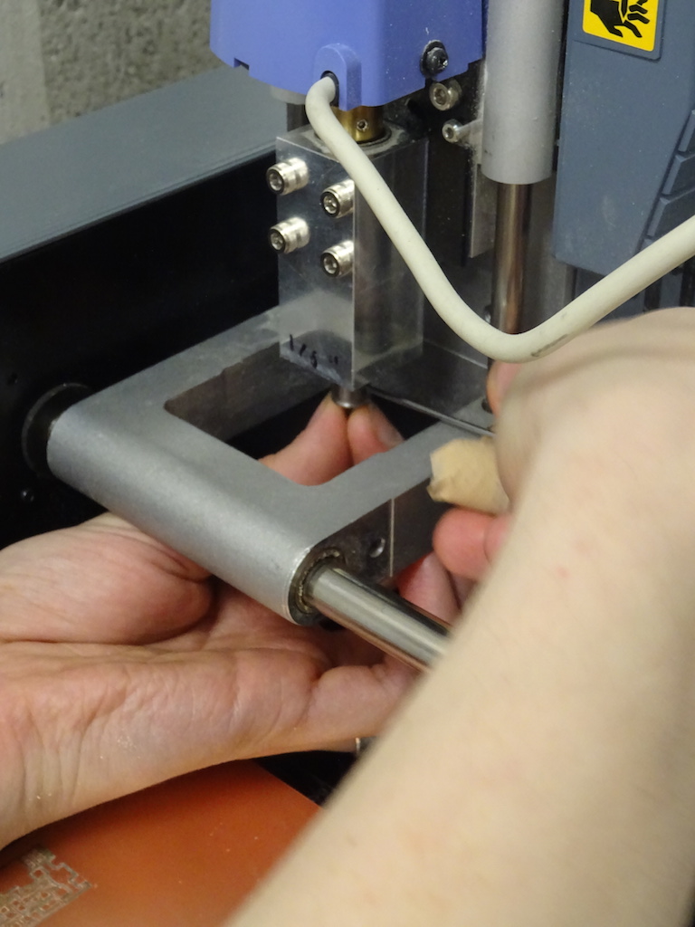
-lower the bit and tighten it.
-press calculate to see it is the right image (not the inverse). check the other settings. the cut depth is at 0.6 mm - we will try it.
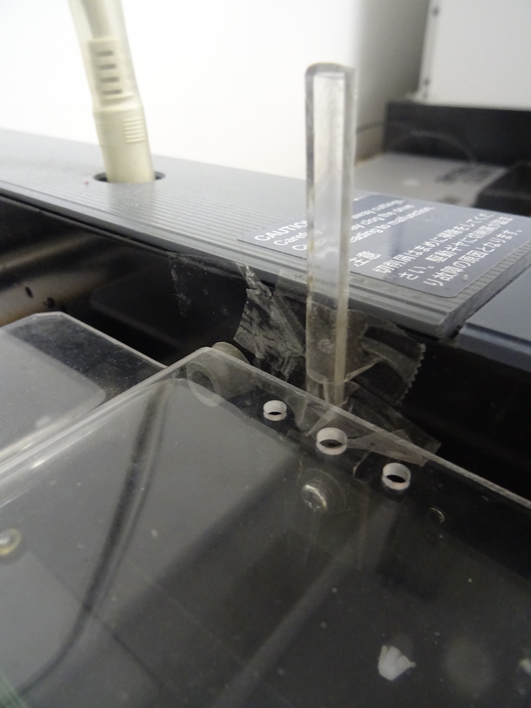
-put the lid on. check the hack piece of acrylic that is supposed to sense when the lid is on. (it can move and then the machine won't run.)
-press send.
-to mill the second board, change the x to 25. press xyz0.
-level the bit manually. press zjog. choose the machine, press zjog again to check. press send.
It is not cutting through everywhere so we cancel the job and change the cutting depth. It was at 0.1 instead of 0.15 so we change the depth.
We press up and down buttons together to zero it. Send. It still doesn't cut through (Niklas points this out) so we start it again with a cut depth of 0.2. This is still not working so we start a completely new mill. The same again for the outline.
-hoover the dust away and if needed scrape away the excess from the board.
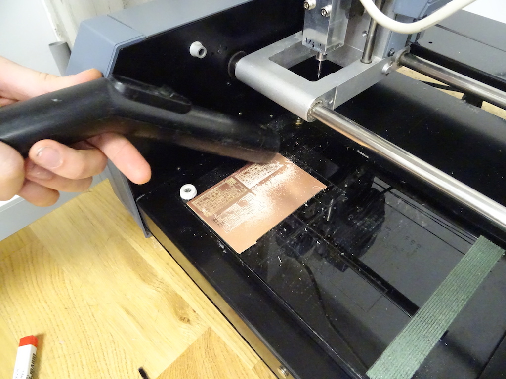
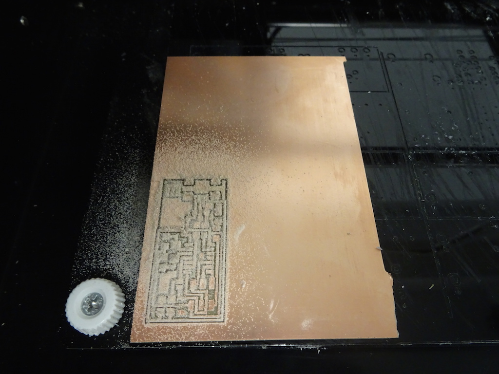
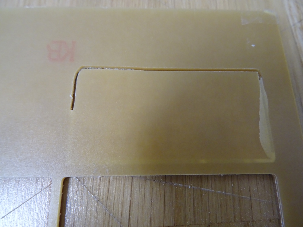
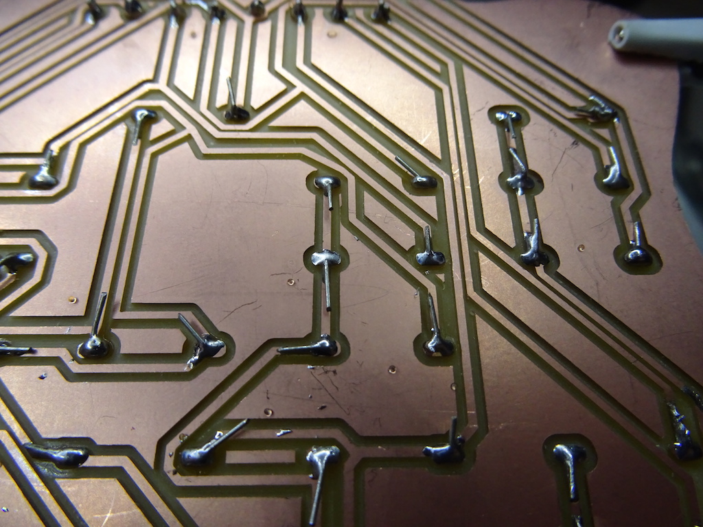
Now we have two boards.
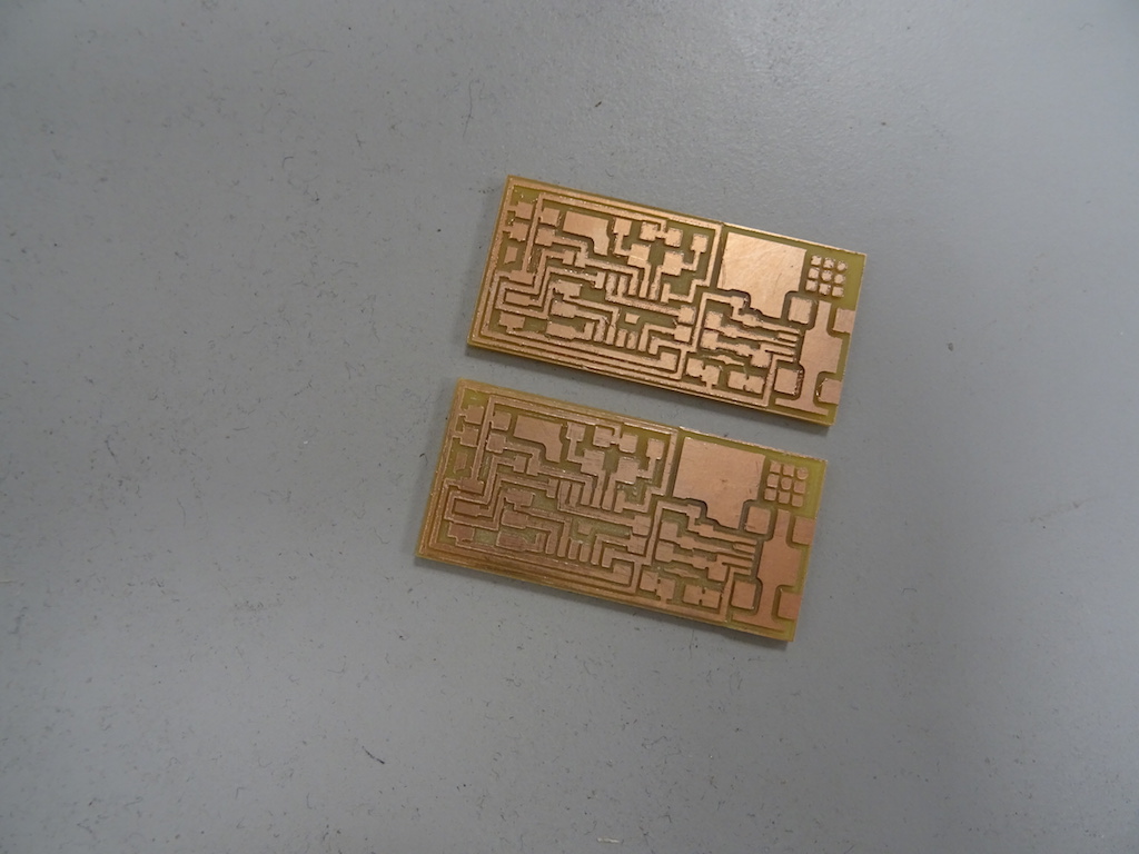
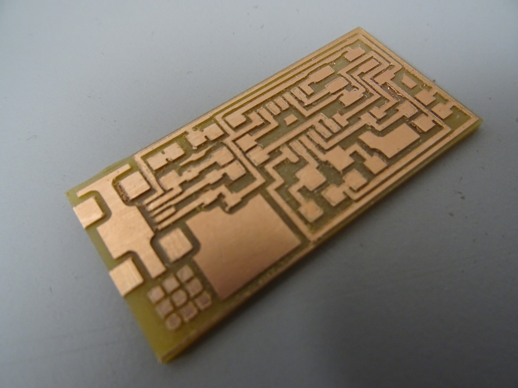
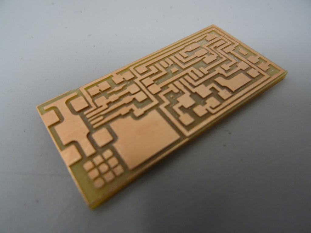
The first board we milled looks nice and clean. The second one does not, even if we began with the exact same settings.
I then have two tries to mill another board. The first time there are two of us who spend almost the whole afternoon trying to do it. Then it is because we cannot connect to the server but we cannot figure out what to do or why we can't. Finally someone comes in who knows the Modela and he does some things in the Terminal. Then it works - but the timing is bad because the lab is closing.
The second try, first by myself and then with the lab manager, we try and try again to mill another board. This time the problem is determining the z-position. The manager is not used to using Fab Modules and usually does this in the Windows environment. As yesterday, he also has to constantly leave to go and help other users. Finally I send the traces (cutting depth 0.15), hoover up the dust, change the end mill (to 1/32) and send the outline. I am very careful about getting the bit to the right position, tightening both screws and then getting the correct zero position. But at one point there is not a nice noise, and at the end the board is not cut through. The mill actually falls right out of the chunk (!) and it is broken.
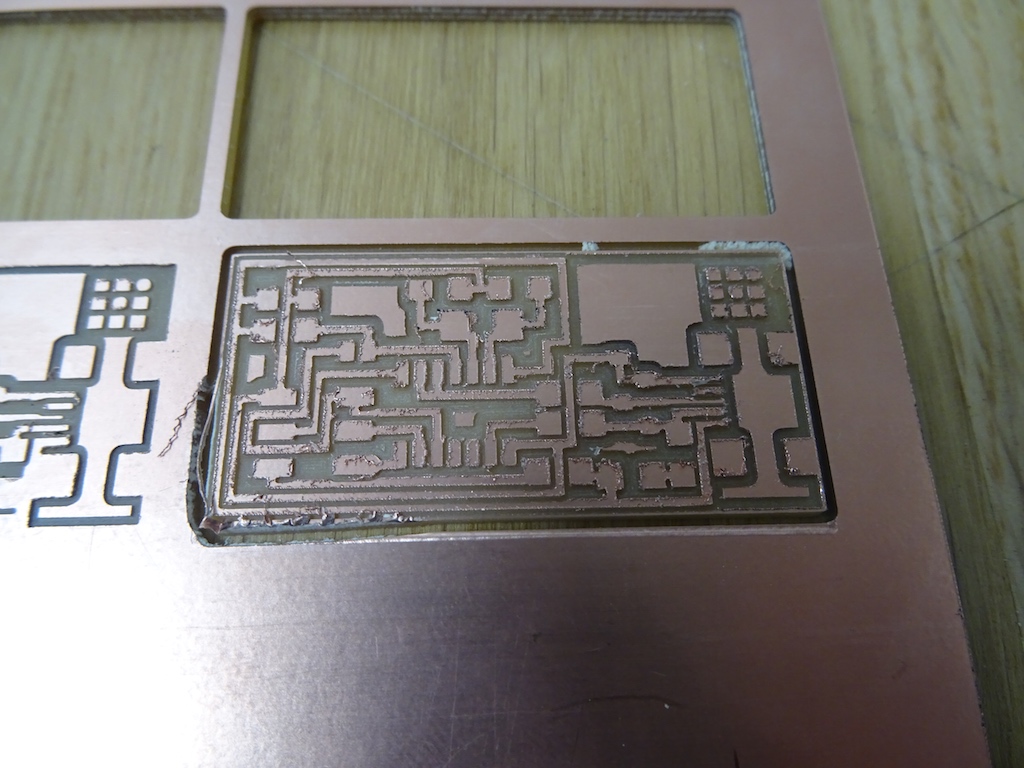
I have to assume it was a problem with zero-ing the tip, but the manager changes the chunk and spindle for the next user and the next job. Later Charlie also suggests taking the spoilboard away and doing the job on top of another unused PCB board, to make sure it is perfectly flat. Next task: soldering.
The next day I learn that someone else also broke an endmill so there was seriously something wrong. Then they discovered that the screws were loose on the spoilboard. I also realize that I don't need to make two FabISPs for the machine assignment; I need to make one for the electronics production assignment and *then* I need to make two FABNET boards - one for me and one for Charlie - for the machine design. Argh. My brain is too overloaded with other stuff and I'm getting things mixed up.
This overloading makes me feel panicked - I'm already so far behind on the previous exercises, and all this electronics stuff is so new to me, I feel overwhelmed. I feel like I just want to jump into a Formula race-car and speed-learn everything and speed through the assignments so I don't feel so behind. But Solomon tells me not to worry and to rather take time to go through the lectures and tutorials properly, so I learn the basics properly. He's right, of course.
I then do take some time to go through the tutorials and find out what circuits are. I start with the Sparkfun tutorials that Ali links to on his FabISP page.
-What is a circuit
-Voltage, Current, Resistance, and Ohm's Law
-Resistors
-Capacitors
-How to Use a Multimeter
And then on soldering. I have to check the solder we have to see if it has flux in it. Still, a couple of people tell me they use extra flux. The flux that is here is old and maybe the lab needs to get new stuff, someone else says.
-a tutorial on soldering that Charlie recommends: Beginner how to solder
-another good one: Soldering Tutorial for Beginners: Five Easy Steps
At first I'm not too worried about the soldering, even though the last time I tried it was a very long time ago. I used to be quite good at gas welding and not bad at TIG welding. That was in the 90s, but I'm not too panicked because they share some basic hand-eye coordination techniques, UNTIL I really see the size of the components and handle them. I can't even see them, with my decades' old eyes. WTF.
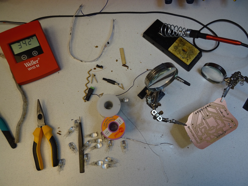
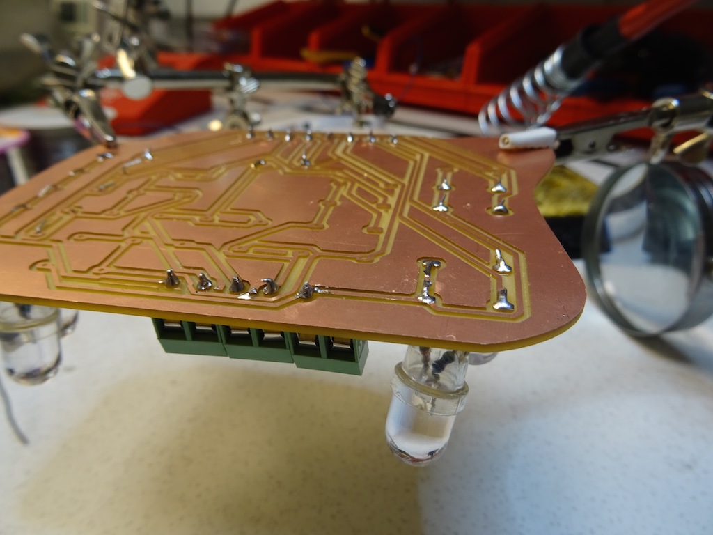
There is a dummy practice board that looks like previous Fab Academy students have been practicing on it. I take a few components and try to solder them on the surface. I have a lot of trouble with it. I try to hold the iron in one hand and the solder wire in the other, so I can't hold the component down with tweezers at the same time. I get one end done and when I pull the iron away, it causes the other end of the resistor to stick up. As I'm moaning and moaning about the difficulty, Jason arrives and says he would have a job I could do for him, something he had brought to do here, where the parts are bigger. It's a circuit he's made for his Showerloop project that has LED lights coming through holes. All I need to do is line up the lights according to the diodes, stick the wires through the hole and solder the point. He watches me do a few and points out both how the solder starts to flow and how it looks shiny afterwards when it's a good solder joint. Then he goes off to the other room where the guys are getting training for the new CNC milling machine.
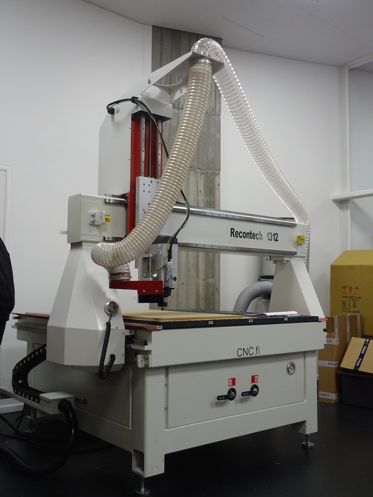
-our new CNC!
Well, this is fun. I'm getting the hang of it and understanding the solder flow. Not all perfect but some are good. I also practice with the braid to remove excess. Jason checks the board and points out a few that don't look like the joint took. I guess when he goes to test it he'll let me know how it went.
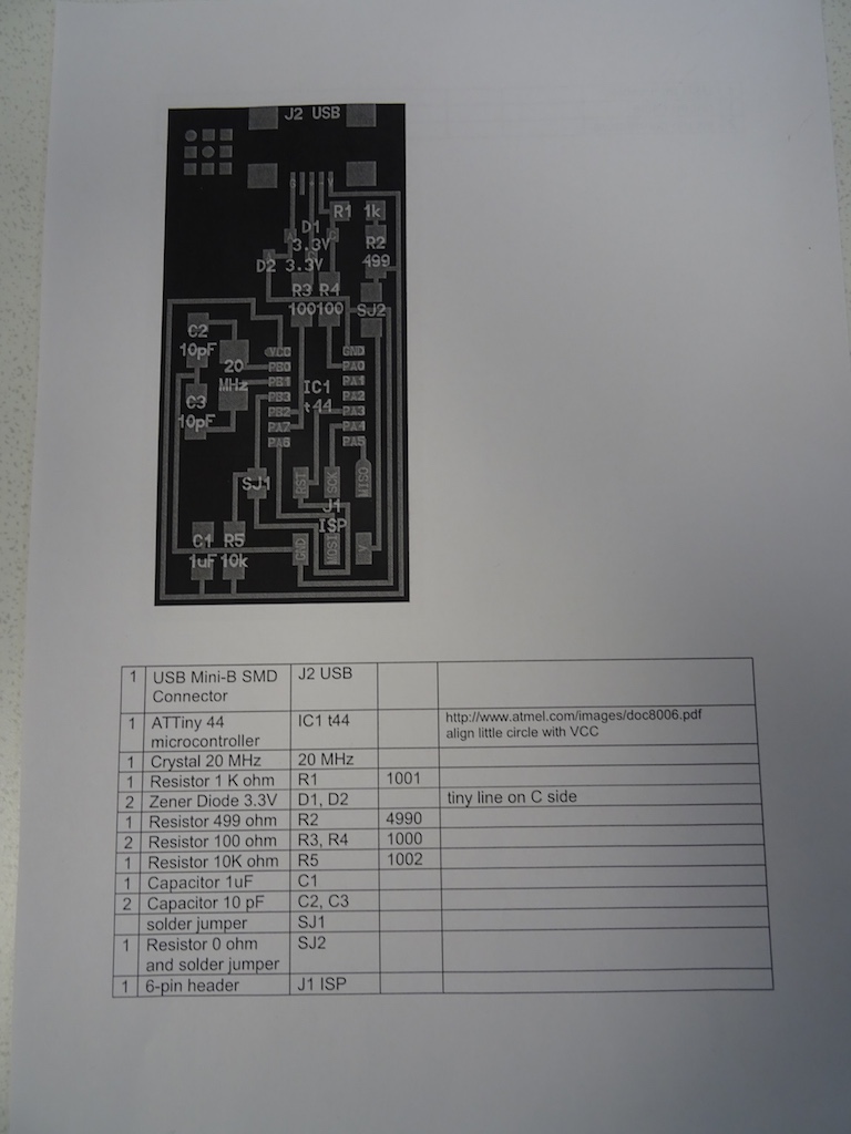
Charlie's assignment page from last year is super helpful, so when I'm brave enough to start on the real board, I go back and forth between his page and the tutorial page in muddling through this. First Solomon says to take away the burrs with sandpaper. I clean it up a bit. I print out the component list, as Charlie had done.
We have only one ATTiny44 left - Solomon had given it to me and I'd squirrelled it away. I ask the guy next to me how he handles the components so they don't get lost. He himself has a circuit that he is testing. He says he takes them one at a time from his box, where he has everything in plastic and foil bags. I decide to gather up only the first few components, and I follow the order of soldering as suggested in the tutorial. Guy Next To Me also shows me how he tins the pads first and then places the component, holding it with tweezers in one hand. He never drops solder directly onto the connection point, the way I had done last week with Jason's through-hole, but rather touches each end so the solder catches and then applies a bit more by dropping solder onto the iron tip and then from there onto the joint.
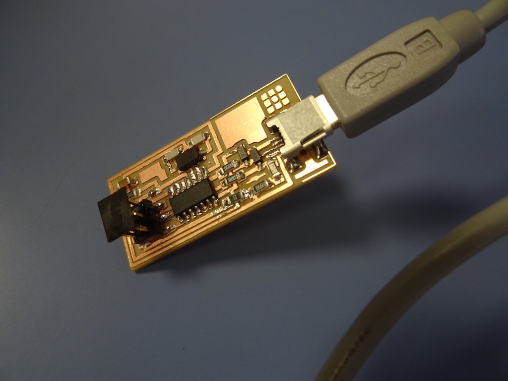
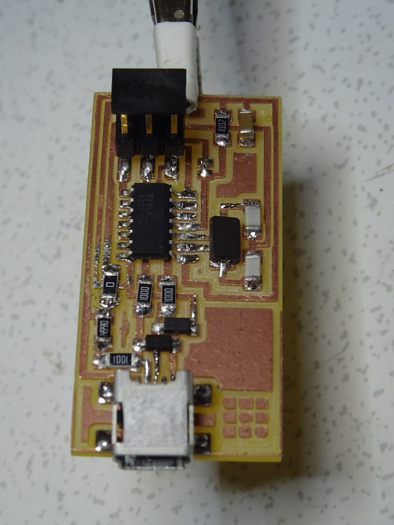
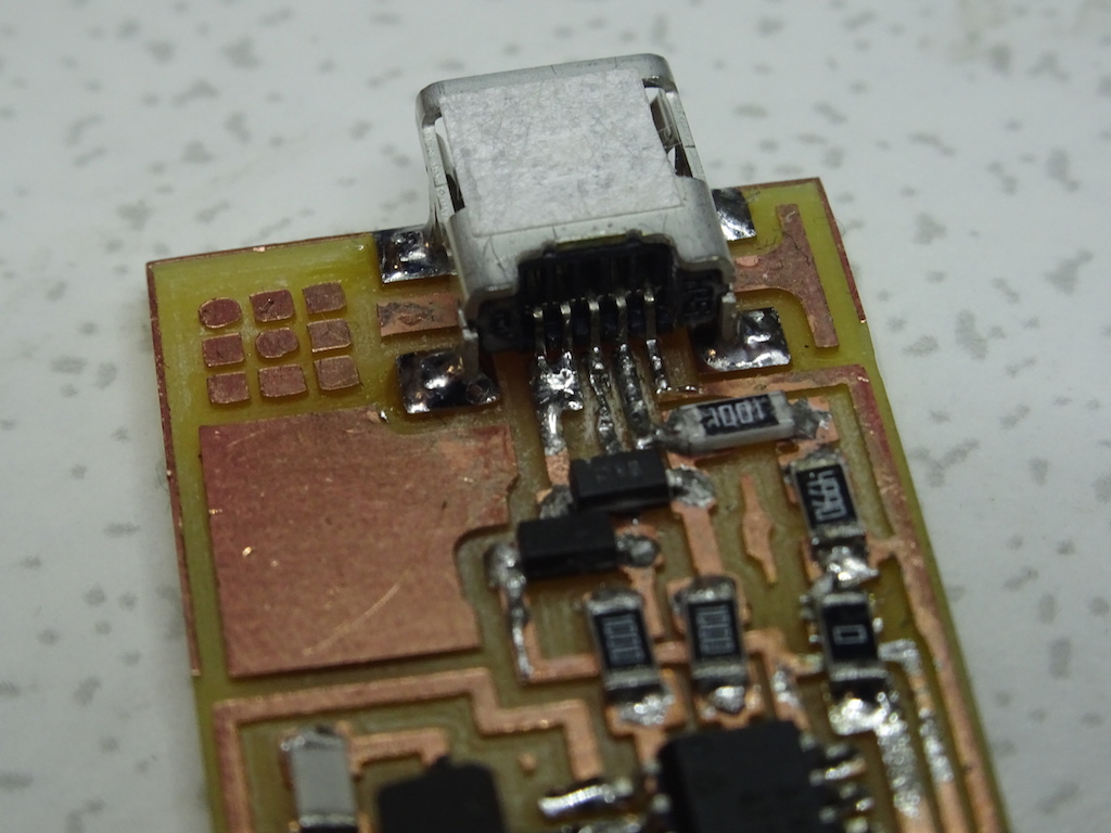
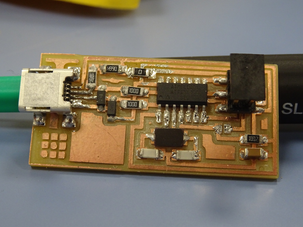
The mini USB connector looks like a complete nightmare, with such small pins and so close together. I manage it, I think, and I manage to remove any solder that crosses the circuits. I hope. I ask Guy Next To Me for his professional opinion and he says it looks good. I continue on with the rest of the components. I need a full light source and the magnifying glass for every single step, but I manage. I find a cable and plug it into the computer, but it says that it is drawing power so there must be a short somewhere. Must check it. To be continued.
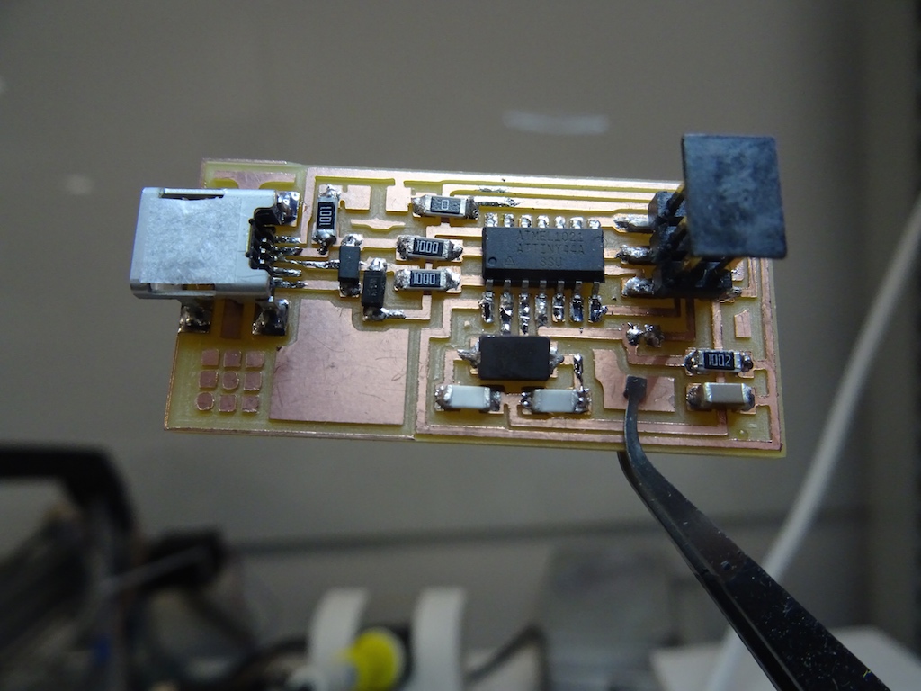
-the board with just one resistor missing. Difficult to photograph.
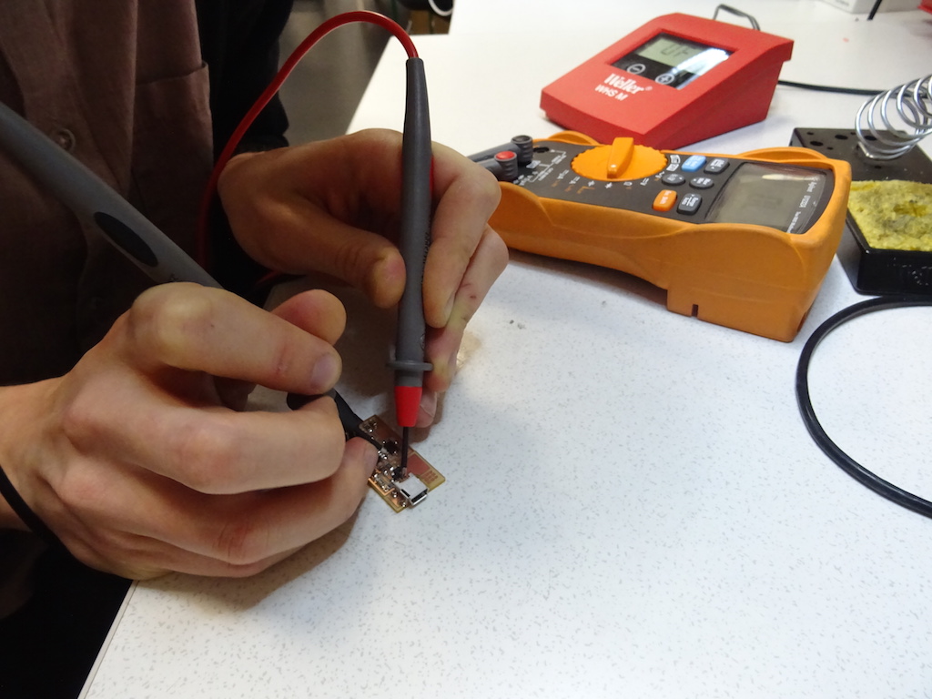
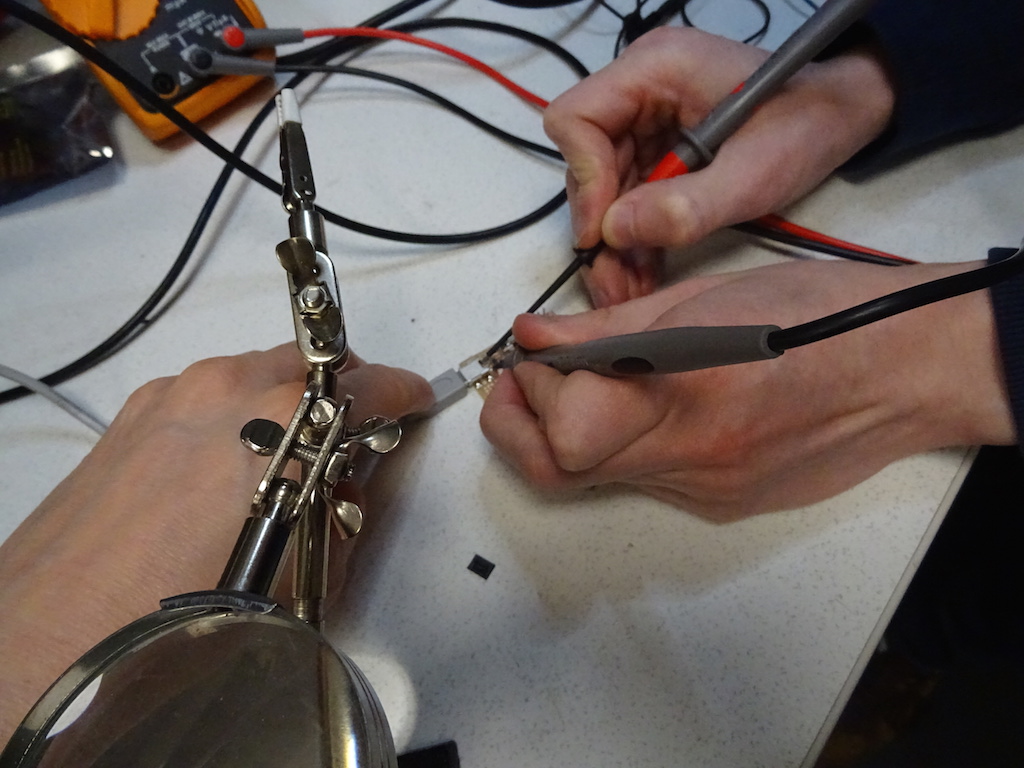
I identify the problem - it's at SJ2. I had misunderstood the instructions. I remove the resistor and solder and redo it. When I plug it into the computer I get no error messages. Niklas also checks the whole board with a multimeter to show me how to do it.
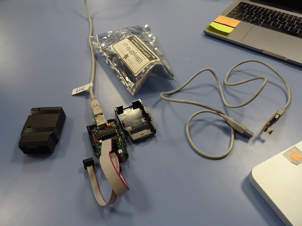
Niklas and I get a programmer and follow the tutorial for programming. I had downloaded and installed Crosspack AVR and XCode. It took some searching to find the right XCode for my ancient laptop running Yosemite (surprisingly), but I finally find this Wikipedia page. We follow the tutorial (downloading the firmware on the Desktop, changing the Makefile according to the instructions). At the 'make clean' command I had to agree to the XCode licence agreements. That was fine; the response was as it should be.
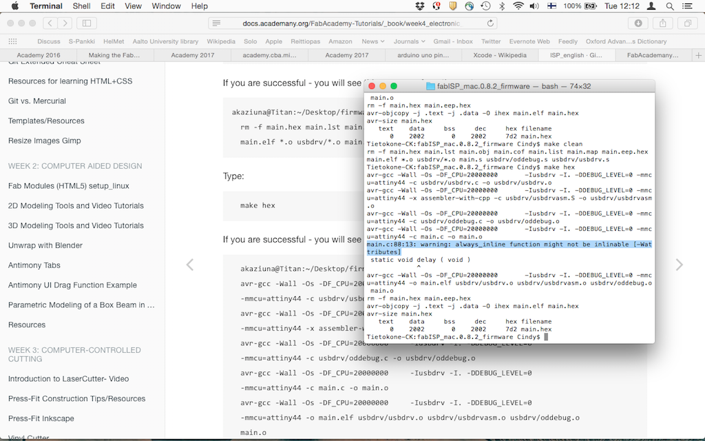
'make hex' - also the response as it should be according to the tutorial.
'make fuse' - also the correct response with no error message.
'make program' - also the correct response with no error message.
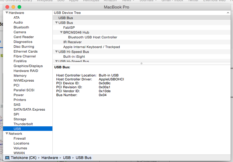
But when we check to see if the laptop recognizes it, the FabISP does not appear in the Hub menu. Maybe it's a problem with the USB cable, so we try another one that I know works - still nothing. We try in my other laptop, not there either. Niklas wonders if it is a problem with that programmer so we switch to the other one and try the whole procedure again.
We check this particular warning by googling it, but we see that it appears in others' logs too.
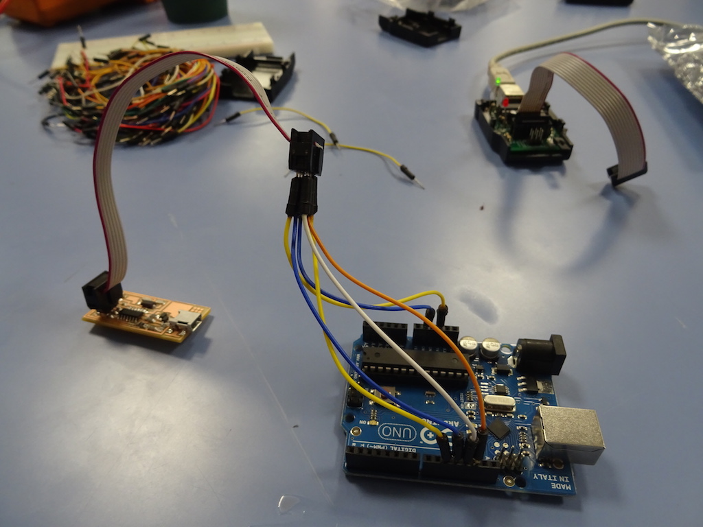
It is still not recognized by the computer. Niklas takes an Arduino UNO to try. We find Massimo's tutorial and this Arduino tutorial and wire it up according to Massimo's instructions.
No success this time either. Niklas suggests there is either a problem in the USB mini header or the chip. But if it is a problem with the ATTiny44, he suggests just doing the whole board again - it will be faster than trying to remove the microcontroller and getting the solder off. Oh - just grrreat. We don't have any Tiny's left in the FabLab. I forget about it for a few days while working on the machine assignment. Then a guy from our university's ARTS electronics workshop wanders in and I ask him if he has any - he checks, but he doesn't. I email the guys from Electroshop in Design Factory and then I go and check their inventory but they don't have any either.

I'm including the photo of Design Factory because it's a famous place and some people are greatly interested in that kinda thing.
So - what to do. I send an email to the guy who teaches interactive prototyping, and he says he has a Tiny85 which is the same but with more memory. He has it in A-Space, which is almost next door and our art and design school's refugee camp / free creative space here on this science-and-technology-and-engineer dominated campus. Perhaps I will replace the USB header first and see if that was the problem. I'm not sure of Life's Little Lesson here - but in the last week I have got to know more about the other workshops and electronics shops on this campus.
Oh! fantastic! Interactive Prototyper has replied with this troubleshooting list:
"if it is reactive to the programmer(s), it's not bricked, i.e. it's not necessarily broken.
Four things come to mind, since you've tried with different cables as well:
-programming failed -> probably not, as you would get feedback from the programmer programming your programmer (heh)
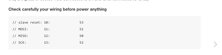
-fuse setting failed -> it's not configured for the crystal -> USB not working due to wrong chip clock -> measure clock-pins with oscilloscope
-fuse setting ok -> crystal not properly connected (ALSO 10pF is a bit small as crystal caps, as it might not start oscillating, manufacturer recommends 12-22pF (see ATTiny24/44/84 datasheet Table 6-9, p.29)
-reset is low -> device won't boot, but is active and r
eads as responsive for the programmers (datasheet, section 19.5, serial programming, p.163)
Checking USB-header connection with a multimeter shouldn't be a problem, just cut one USB-mini cable and measure through the wires + board."
I send him a photo of the board and he replies: "Thanks for the photo, couldn't see everything, but clear enough.
It looks like pin 3 is not soldered correctly. (PB1)
Since this is connected to the crystal (or ceramic resonator?), it would be a prime suspect.
Quite often with SMD-components (especially IC:s, not so much with the passive components) one gets the solder under the pin, however due to some slight tilt, it does not actually touch the pin. Sometimes it does touch, but there is a slight oxidation preventing proper contact.
But there's the catch: when it is measured with a multimeter, the probe tip presses it against the soldered copper, giving the impression that everything is ok.
Very very rarely, such could also be so close contact, that just breathing towards the board, or change in temperature could make it work/not work. I doubt it, though.
However, just add a dab of solder/tin on it, and make sure that the surface tension does its job. Surface tension is a good way to make sure that things are properly connected.
Also it looks like there is no solder lacquer being used. Using such before soldering (e.g. spray) gives considerable increase to the reliability. It cleans the connection when activated by high temperature of the soldering iron."
I try to fix pin 3 and we program the board again from scratch. We get no error messages again, but the computer still does not recognize the USB. Bas asks for high res photos and we talk about the header being the problem. This FabISP is the bane of my existence.

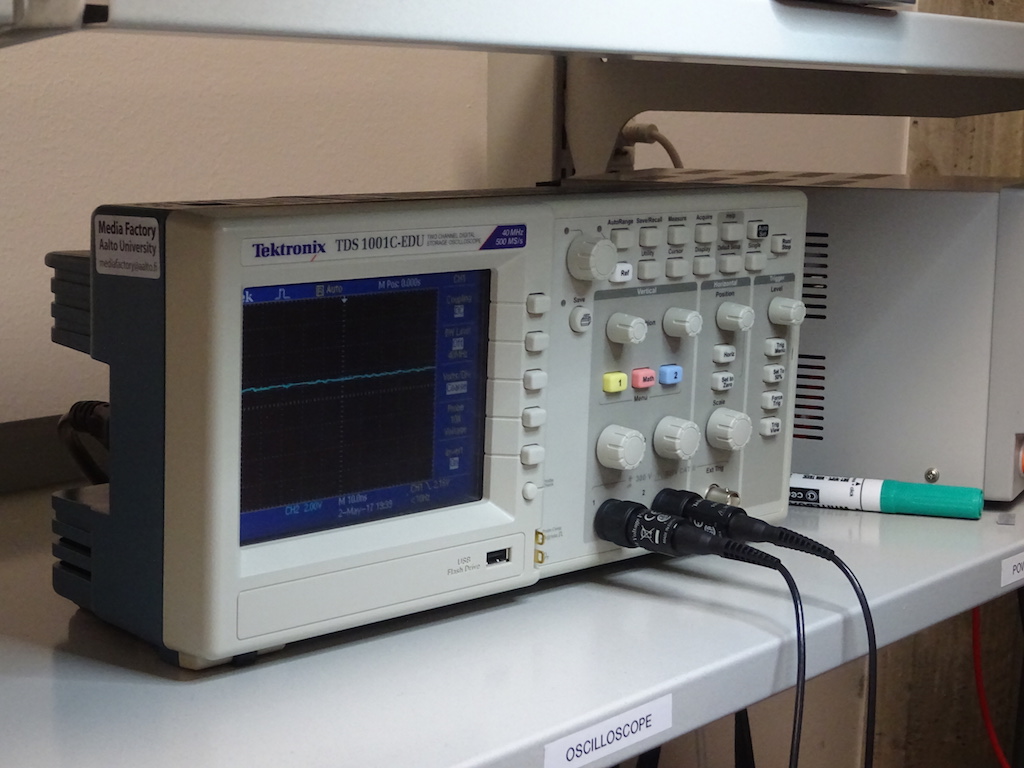
I don't know how to use the oscilloscope and this is not 100% familiar to the others, so three of us gather to try - to test the crystal. GuyNextToMe (his name is Otto) first explains that it cannot be used like a multimeter where you can put the pins (what are they called?) anywhere - ground needs to go to ground. He attaches the ground clip of the oscillator to the ground pin.
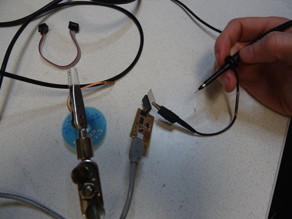
He touches the other pin to power but it is reading less than 2V. He asks us if we checked if the board is receiving power and we all look at each other like, hmm, we were checking for shorts but didn't actually check that. He takes the multimeter and checks the board.
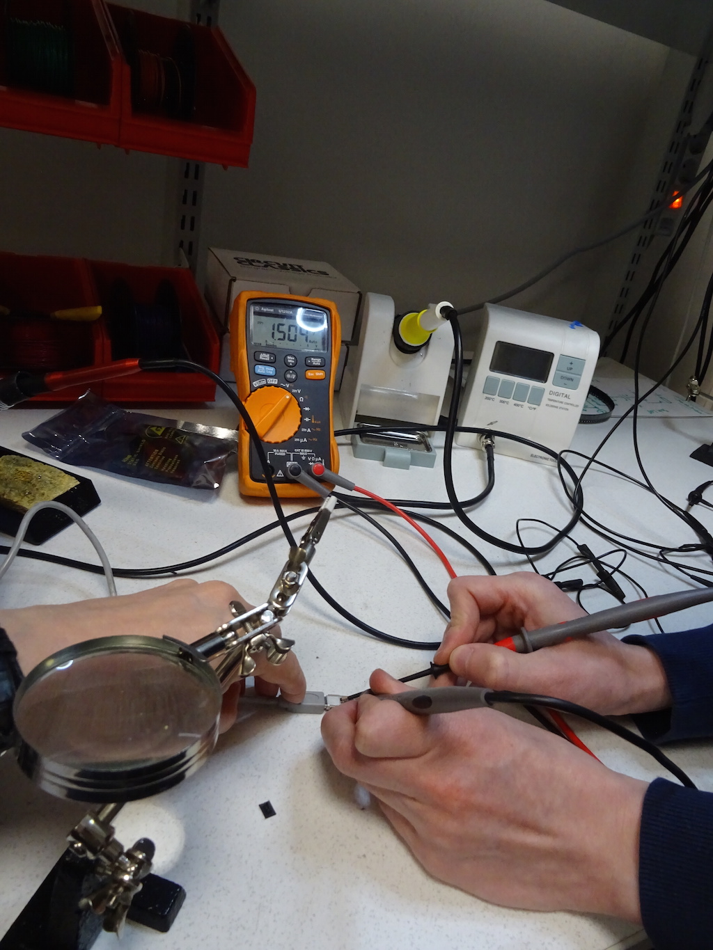
Otto and Niklas are examining the board by sight and with the multimeter. They still can't see anything visibly wrong. Otto says, "This is amazing when something so little can go so wrong." We look at his own very complicated board and shake our heads dramatically in dismay. They start to get suspicious about the ground pin on the USB header, the left most one (if I have understood correctly). They don't get a voltage reading from the left one but they get one from the one beside it. Otto shows us his own board where he joined those two pins. Niklas suggests just joining them and see what happens.
I drop solder on it and then plug it into my laptop. And MIRACLE! The FabISP appears!
I'm so relieved I start dancing and singing around the lab and the guys just shake their heads.
I remove the solder jumper and will hope for the best when it comes to using it for programming. It's not a pretty board and the soldering is not stellar, but it's a good start.
Fab Academy goals:
Describe the process of milling, stuffing, de-bugging and programming.
Demonstrate correct workflows and identify areas for improvement if required.
Cindy's goals: (a) Learn milling and soldering. check
(b) Understand some first basics of circuits and components. check
(c) Understand what this thing is and why I did it. well, getting there...
Notes and reflections to come.
Notes and reflections to come.