Drawing of Final Project in progress....
Practicing drawing and drawing programs:
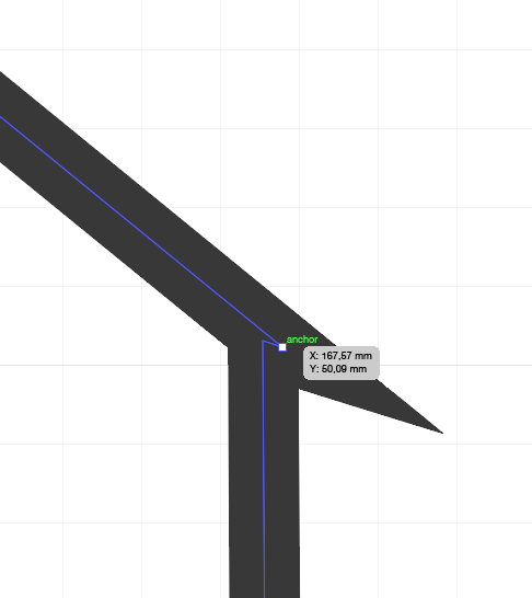
On other drawing: I've used Illustrator, not well, but enough for my needs (drawing diagrams for academic papers, mainly). Now I've spent a couple of days messing with Illustrator and learning about anchor points and joining paths. I was having the problem of joining paths but not getting smooth corners. This is 2016 before I have an idea for a final project.
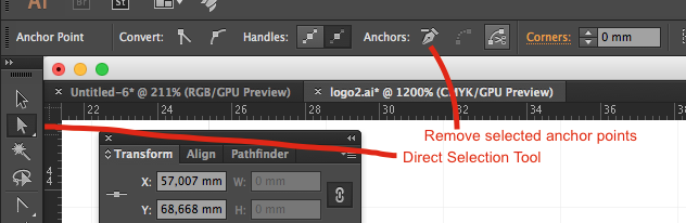
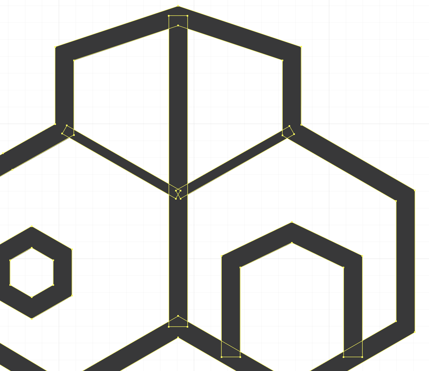
By zooming in much more I could identify the anchor points I had to delete, selecting them by using the Direct Selection Tool.
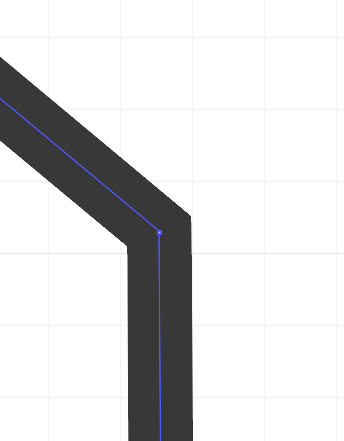
But I continued to have problems joining paths and trying to break paths at anchor points. I started drawing the thing again and by trial and error clicking on 'merge' and 'group'. Of course this is the problem with the documentation - I just did this without remembering to take screenshots.
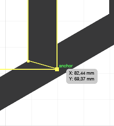
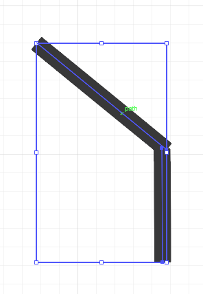
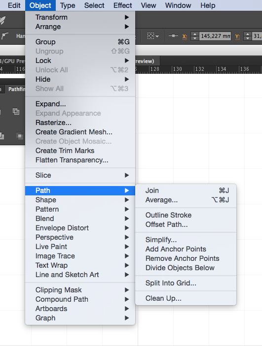
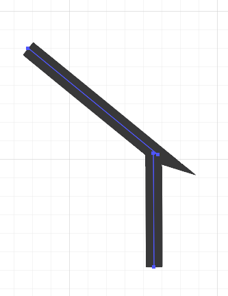
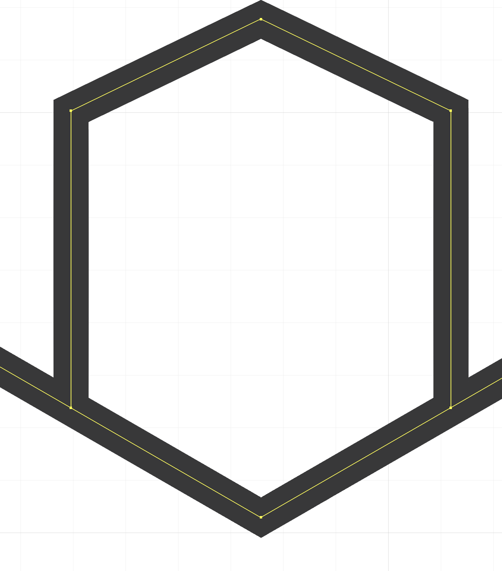
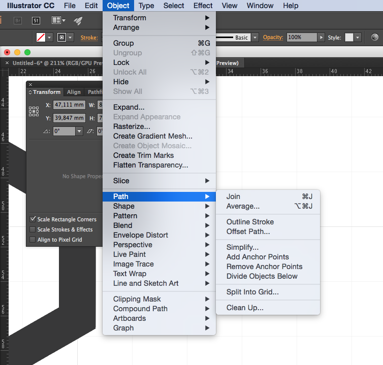
I used hexagons that I merged into the outer outline and added the other shapes (the inner lines and the 'doorway'). I outlined the lines: Path - Outline Stroke. I tweaked the proportion of the top by selecting the top anchor points and moving them all down together with the bottom arrow on the keyboard. I changed the width of the inner diagonal lines by moving their anchor points. Since this moved everything around, I made a new Layer, put the same basic hexagons there, and lined up the anchor points with the background hexagons. I could then hide this layer when I didn't need it. This is a super boring description, but every time I work with Illustrator I find that some steps are better done first and then other steps. So mess and chaos and randomness first and then do the whole darn thing again in a better order.
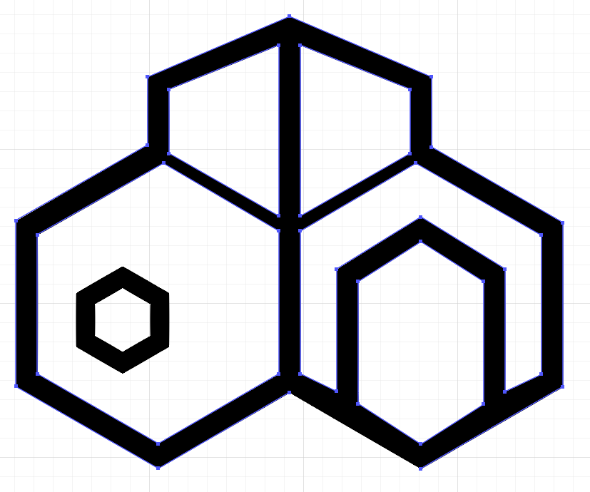
Now I have a path outline that I can try on the vinyl cutter for the cutting exercise. And a bit more knowledge about Illustrator.
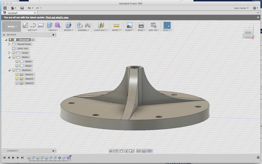
For the machine design assignment, we need 3D printed parts that connect our discs to our stepper motors. (I will do it this way here in Finland; Charlie will decide if he will do it this way in the UK or another way - as he has the motors with the integrated threaded shafts.) (See our page here. While Charlie's design was printing on the ZYYX, Niklas showed me a few things on Fusion360, and we created our own version of the shaft mount. This is not yet a full documentation, as I will do this exercise later, but some hints I wrote down.
-Sketch->Create Sketch
-if you want a circle and have it in the middle, click Coincident under Constraints. Click on the centre point of the circle and then the centre point of the drawing space.
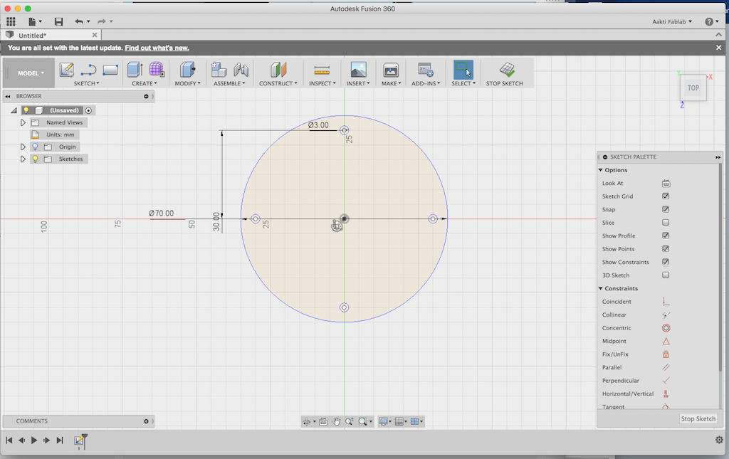
-if you want to move the object, Modify -> Move/Copy
-make a small circle (for the hole). From Sketch -> Circular Pattern -> click on the first circle and then on the centre part of the main circle and the small circle (i.e. the hole) will copy itself.
-click on D, click on the object and move the mouse - for Dimensions.
-Create -> Extrude: turn the view (top right corner) into an isometric by dragging the mouse, and an arrow appears on the object - click on the arrow and move it and the shape will extrude. I did this with the middle shaft as well as the arched pieces coming off the centre shaft.
-Operation -> Join. To be continued.
This was the recitation for week 2 in 2016. It was really interesting. Notes and reflections to come - I'd like to watch it again. There was no recitation in 2017.