Computer-Aided Design
This week the focus is on 2D and 3D design. I chose to focus on Fusion360 for three reasons: the easy interfacing with the laser-cutter as Fablab manager Matthieu explained to me, a friend working in industrial design uses Fusion360 (it might be interesting for me to have support and/or to see how people in different domain uses it), it support parametric design (obviously) which will be the focus in week3 with machines.
I decided to design (2D or sketches) a holder for my headset that could be made out of cutting cardboard. After watching a (and a longer one too) I tried to work essentially with constraints.
When you choose Create Sketches, the Sketch panel appears and in the second section I tried to enforce constraints in my design.
At the end, I was not satisfied with the result and the process I chose. The result seemed unwieldy and inelegant. I watched another video tutorial to learn some more and focused on parameters.
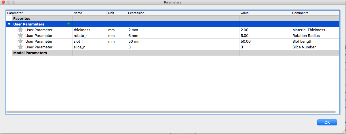
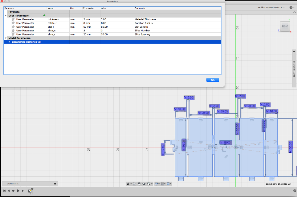
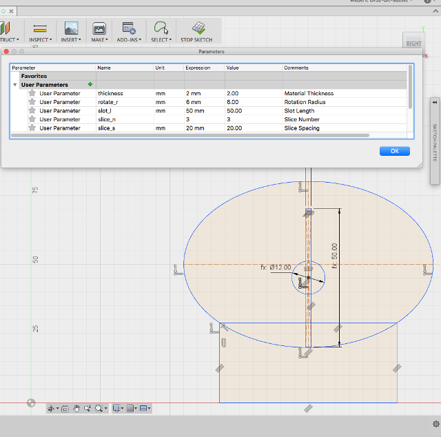
Contrary to the video, I decided first on my parameters: thickness of the material, length of the slots, rotating radius, the spacing of the slices and the number of slices. This feels appropriate in that they can always change, but to first pinpoint what are the important elements of a design seems quite natural to me.
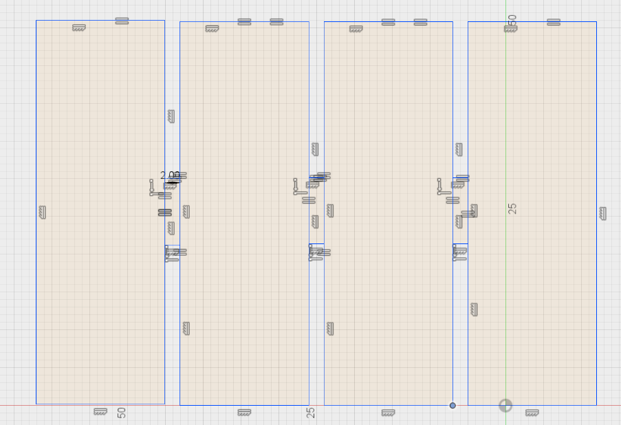
With that in place I started to draw rectangle for the holder and insert in the dimension the parameters that I decided upon. The result is the holder that rotates in order to hold in places the head-shaped slices.
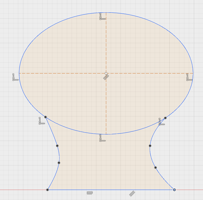
Then I designed the head-shaped slice (in a schematic way). I made it from an ellipse with a rectangle for the neck. Then I sketched (on the vertical symmetry axis) the rectangle for the cut out and the circle to allow for rotation of the narrow part of the holder. These dimensions were already part of the user’s defined parameters: the width of the rectangle is actually the thickness of the cardboard and the height of the rectangle is the length of the slot.
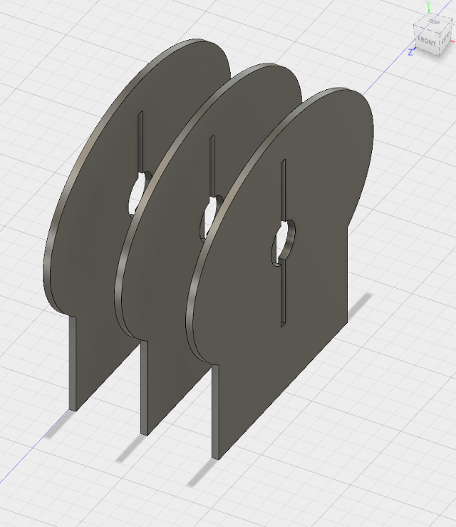
Just to be more able to visualize the 3D shape, I then extruded the sketches into the third dimension, copied it and paste it twice.
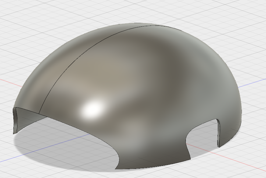
I then tried to model the headset itself. Of course the best would have been to work from a 3D scan of my head, but it is the best way to advance in design.
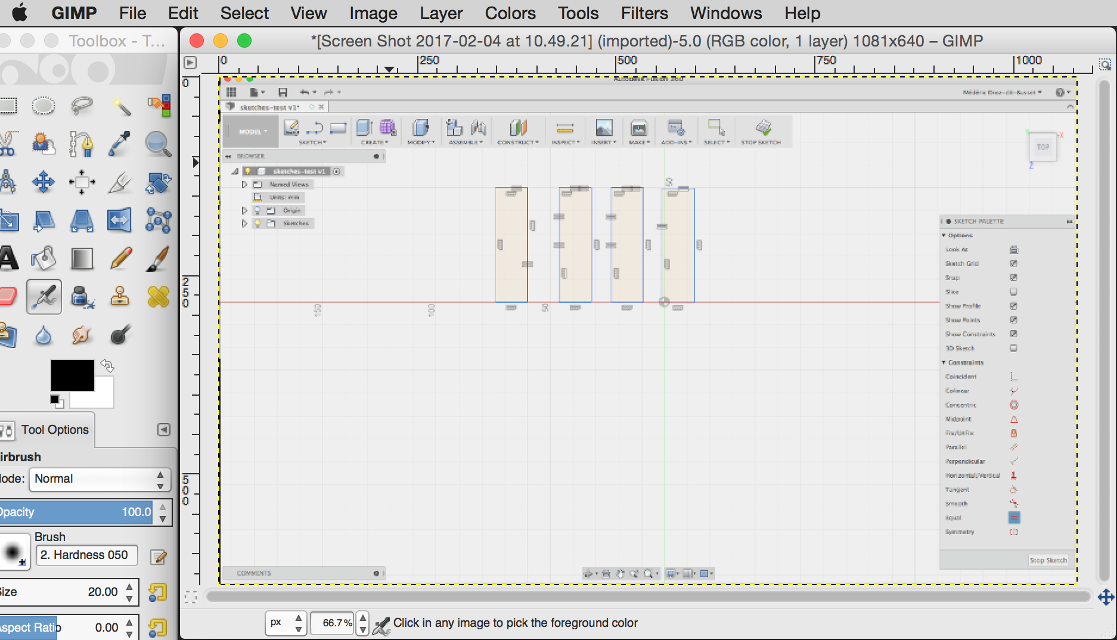
Regarding the screenshots, they were taken a MacBook Pro laptop and then resized with Gimp. Since I am familiar with Adobe Photoshop, I wanted to try out the Open Source software Gimp.
I tried to model the head shape in OpenScad. First, I watch a short video tutorial, then I also read the the User Manual to find some primitives.
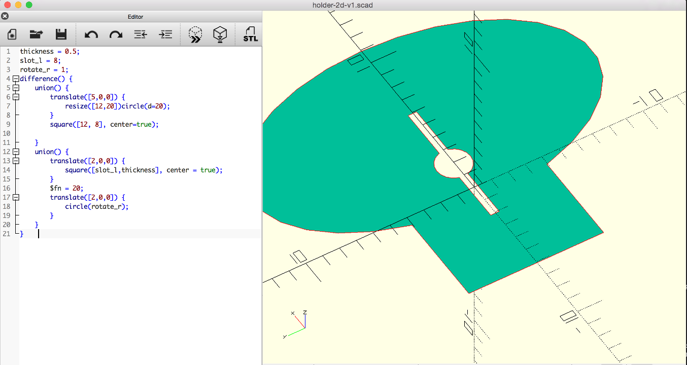
Regarding OpenSCAD, I proceeded the other way around. I had the design in mind: to replicate the head shape from I did beforehand with Fusion360. From what I had seen, the software seemed a bit less welcoming than Fusion360, so I focused not a creating a design, but learning how to do this humble design. I must say that the constraints of “coding” your design are quite high and it does not seem as wieldy as Antinomy (which I did not use for now) – when linking objects and functions in graphs.
The fact that you cannot go from the design to your code, but only from the latter to the former is not helping understanding your design (which is something important for a first timer). Basically the right hand side of the screen is a display of the design and not a shape you can interact with. This is not the case – as far as I understood the demo – of Antinomy, and of course not the case either of Fusion360, where the interaction with the design is (almost) everything.
With that said, there is a powerful elegance to that software in the sense that the expression of symbols (code) can be used solely to form complex shapes. I will try to toggle between the Fusion360 and OpenSCAD if I can (and give a try to Antinomy, if time permits).