Output Devices
This Week's Assignment:
Add an output device to a microcontroller board you've designed and program it to do something See details here.
-
Create a Hello Stepper Motorshield Board
This might be a way to control my Stepper Motor for my final project instead of the Adafruit Shield.
-
Programming
Explaining the process and result
-
Materials, Machines and softwares used
- SatshaKit
- Electronic components (see details for Hello Stepper Bipolar)
Machine :
CNC mill, for the fabrication of the PCB
Software :
- Arduino IDE to write the program and read it
Files
All files can be downloaded here.
A bit of lesson learned: Stepper motor drivers are specifically designed to drive stepper motors, which are capable of continuous rotation with precise position control, even without a feedback system. I have used AdaFruit Motorshield at the beginning of the process for my final project. AdaFruit motor drivers offer adjustable current control and multiple step resolutions, and they feature built-in translators that allow a stepper motor to be controlled with simple step and direction inputs.
An H-bridge is an electronic circuit that enables a voltage to be applied across a load in either direction. These circuits are often used in robotics and other applications to allow DC motors to run forwards and backwards. It can control motor to turn right and left - source: Chee Hong. Basically, "from microcontroller we can not connect a motor directly because microcontroller can not give sufficient current to drive the DC motors. Motor driver is a current enhancing device, it can also be act as Switching Device. Thus we insert motor driver in between motor and microcontroller. Motor driver take the input signals from microcontroller and generate corresponding output for motor." - source: Arduino guide
Let's see what is on this board...
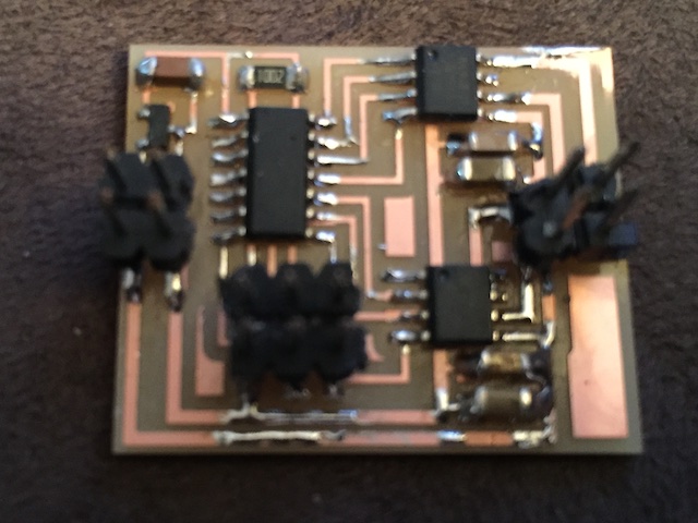
I made Neil's Hello Stepper Bipolar board. 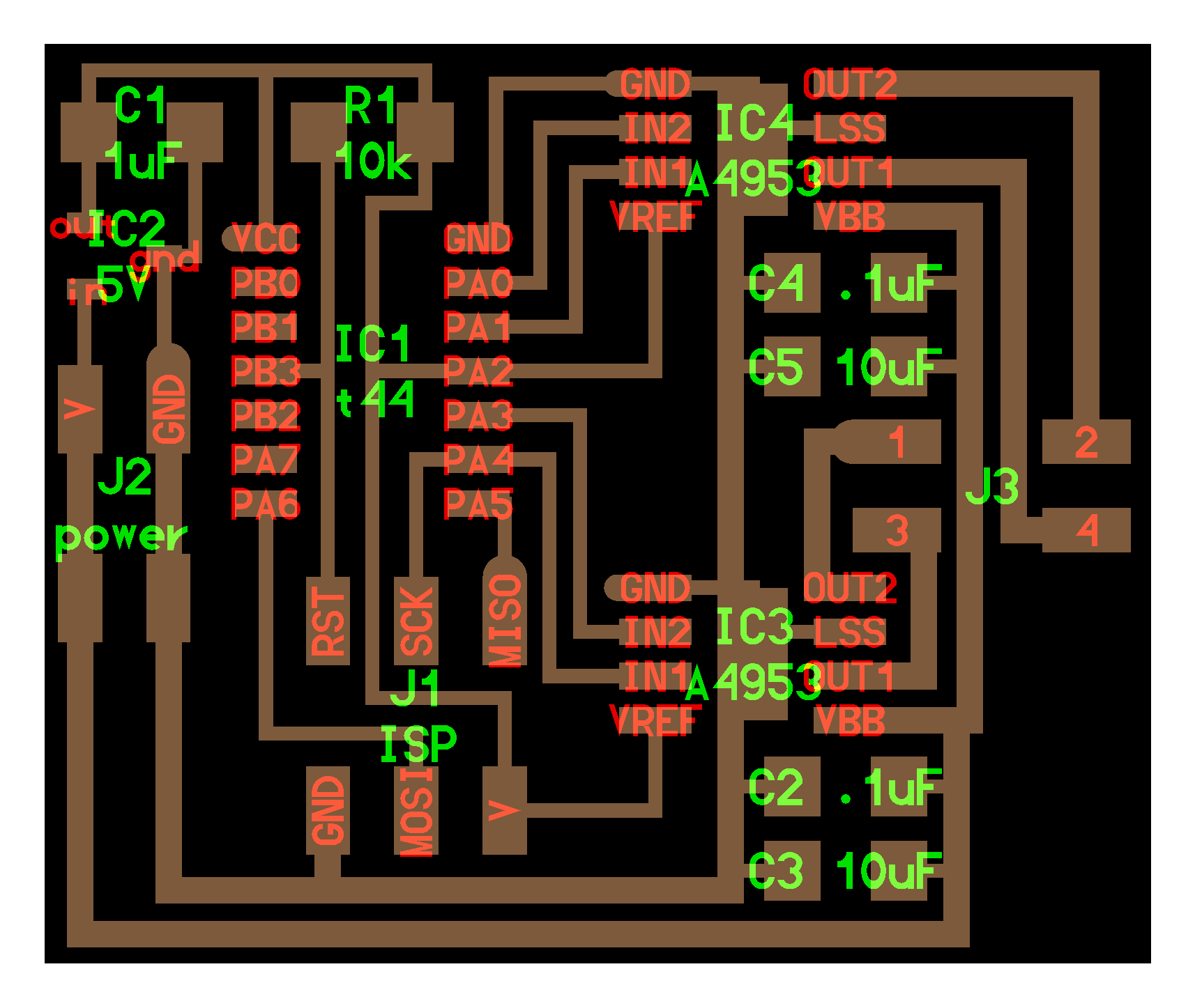
 This board has a ATtiny44 and two Full-Bridge DMOS PWM Motor Drivers A4953. They are designed for pulse width modulated (PWM) control of DC or Stepper motors (2 A4953 control 1 Nema Stepper or 2 DC motors). The A4953 are capable of peak output currents to ±2 A and operating voltages to 40 V.
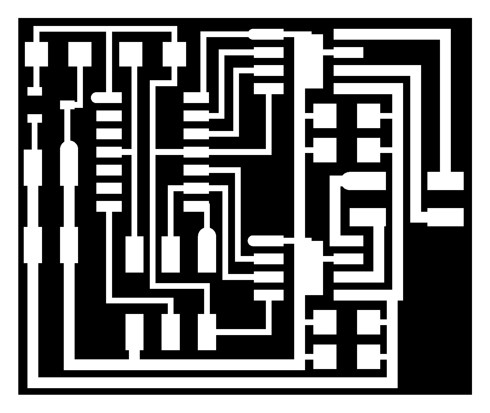
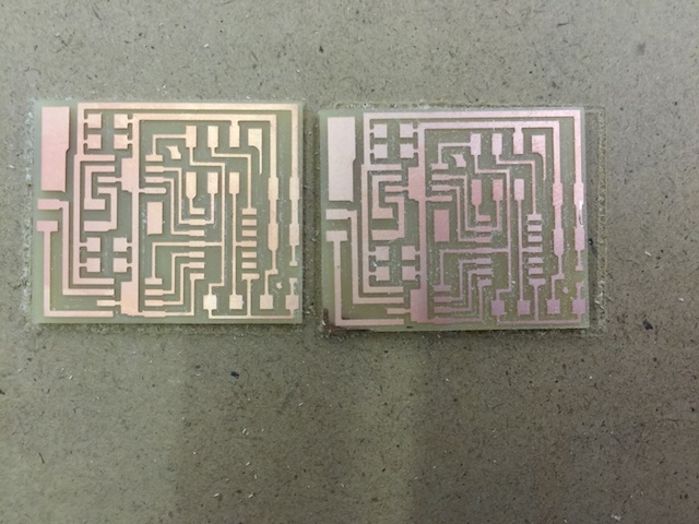
First thing I had to do is make the gcode with FabModules. I used the same steps as my first hello board, the trace are mades with 1/64 end mill and the frame with 1/32 end mill, the only difference is that instead of choosinf Roland type file as output I chose generic gCode, which has a .nc file extension.
Mach3
I am using a home made CNC at the MakerSpace Noth in Ottawa and Mach3 software to control the CNC. I like that we can use the arrow to control the movement of the spindel on XYZ axes (Page Up, Page down for Z axes) as opposed to clicking with the mouse on a sofware made button. Shift Arrow, Page up or Page Down makes it moves faster and Control makes it move a 10th of a inch. 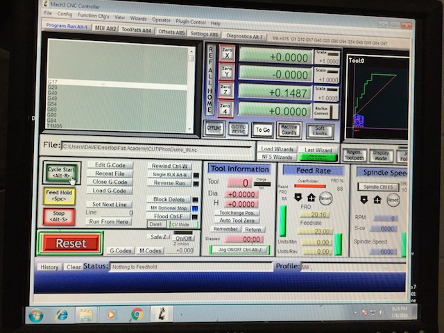
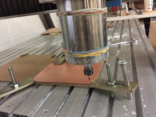
Result Milling and soldering
I programmed my board using the made FabISP and the provided make file and C file from the tutorial. Downloaded the files, CD the folder in the Terminal and did this command. This programed the board to make a full turn :
sudo make -f hello.stepper.bipolar.44.make program-usbtiny
I kept having this error. The FabISP could not detect the ATtiny44 microcontroller. I tried debugging with Roman for another case and it took hours so I decided to resolder.
honesavanhs-MacBook-Pro:Flash phonesavanh$ sudo make -f hello.stepper.bipolar.44.make program-usbtiny
avr-objcopy -O ihex hello.stepper.bipolar.44.full.out hello.stepper.bipolar.44.full.c.hex;\
    avr-size --mcu=attiny44 --format=avr hello.stepper.bipolar.44.full.out
AVR Memory Usage
----------------
Device: attiny44

Program:     504 bytes (12.3% Full)
(.text + .data + .bootloader)

Data:          3 bytes (1.2% Full)
(.data + .bss + .noinit)


avrdude -p t44 -P usb -c usbtiny -U flash:w:hello.stepper.bipolar.44.full.c.hex

avrdude: initialization failed, rc=-1
         Double check connections and try again, or use -F to override
         this check.


avrdude done.  Thank you.

make: *** [program-usbtiny] Error 1
Wiring
Here is the wiring: 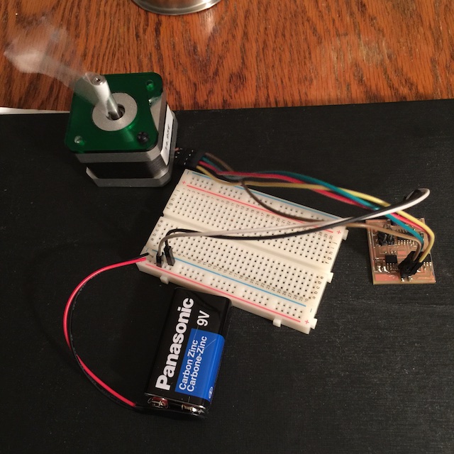 The motor studdered at first, and I learned that the A4943 might have been damaged, I did not know which one so I changed them both (I did not have an oscillator with me). In the process the copper came out partly and luckily I was abble to stick it back. I had to use this glue :
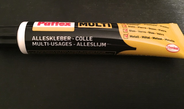
For wiring information I learned that I can use an ohmmeter and start reading resistances between the leads.I got different values depending on which pair of leads I measured. The lowest resistance I found was the coil resistance. I can then use I=V/R to compute the coil current. This also give me pair coil information. Because color of coils can be different.
Result
NOTE
Dual Bridge
I did not get a chance to finish the dual H-Bridge. I broke an end mill while trying and the second one was really not optimal.
Compatible with PhonDUINO V2.0 using Atmega328p
Eagle CAD Software
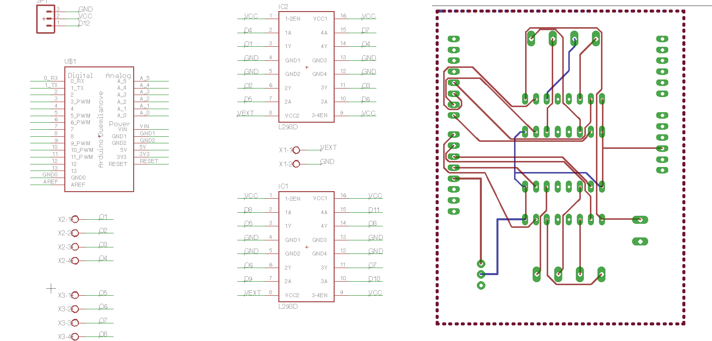
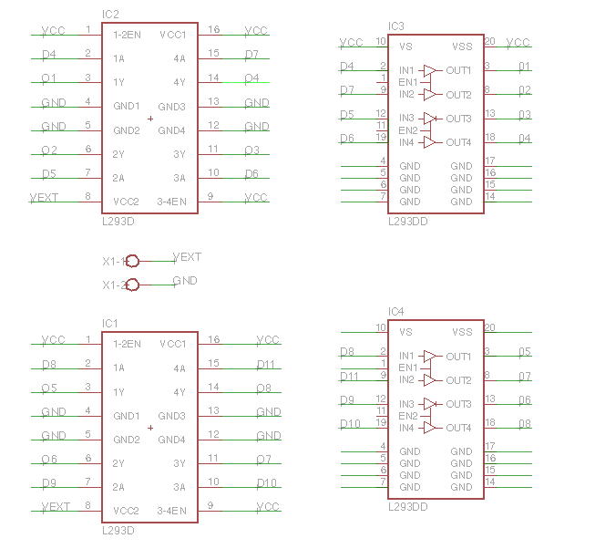
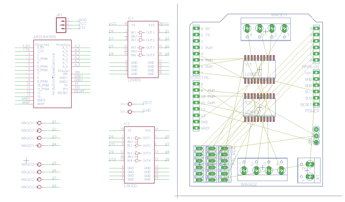
Now that I am familiar with H-Bridge using Neils design board. Lets make my own board using Eagle Cad sofware. All this is new to me so I started with little aid with Allessandro Papaleo motorshield design based on Adafruit same drivers. He made it for his drawing robot using L293D motor driver. I have the surface mount version of the microcontrolor, the L239DD so I switch them in the schematics. I could not use the replace component fonction as they were differents. I associated the correct Pin connection. I had to Google search a while to understand where they belonged. I also added 18 pins for accessibility for my sensors connections, 6 GND, 6 VCC and 6 analogue pins (0 to 5). Here is the library I used for the driver: ST Microelctronics CAD Libraries for Cadsoft EAGLE Software. Below an explication of my understanding. I wished we had more support on board design. Hope someone can later tel me if this is right.
Previous board
Previous Board Pin Configurations
Modified Board Pin Configurations
Lessons learned from reasearch:
- L293D and L293DD has diode for protection, it I didn't needed to add the protection diode manually.
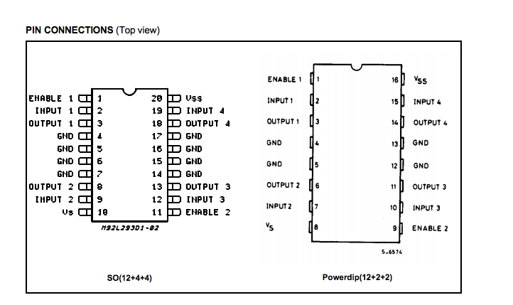
- The L293D is assembled in a 16 lead plastic packaage which has 4 center pins connected together and used for heatsinking
- The L293DD is assembled in a 20 lead surface mount which has 8 center pins connected together and used for heatsinking.
- L293DD has 2 Channels. One channel is used for one motor, in my case, 2 channels for each nema 17 motor as they are bipolar nema motor.
- All Input (Pin No. 32, 9, 12 and 19) of L293DD IC is the output from microcontroller (ATmega328P) and all Output (Pin mo. 3, 8, 13 and 18) goes to the input of negative and positive terminals of the right and the left motor.
Pins Connections Compaired
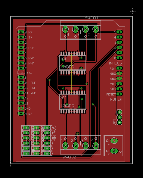
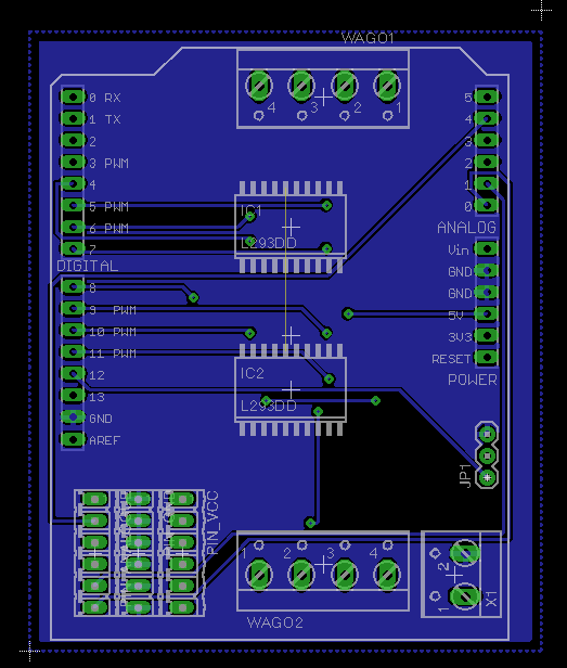
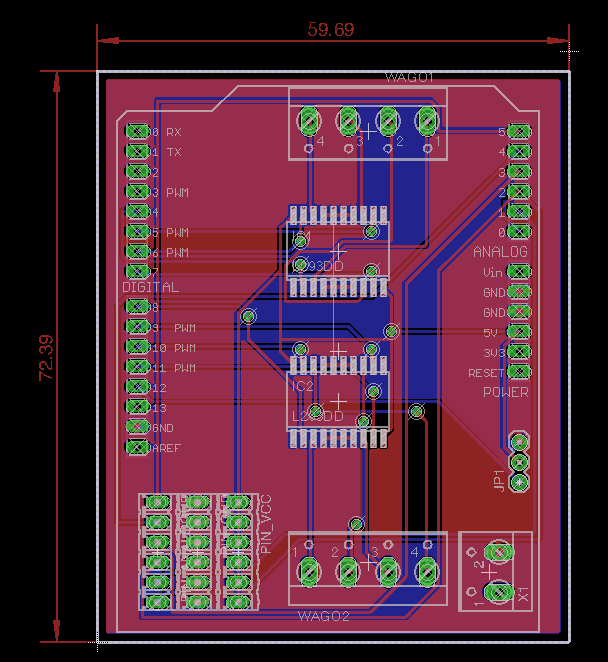
Schematics and Board layout Design
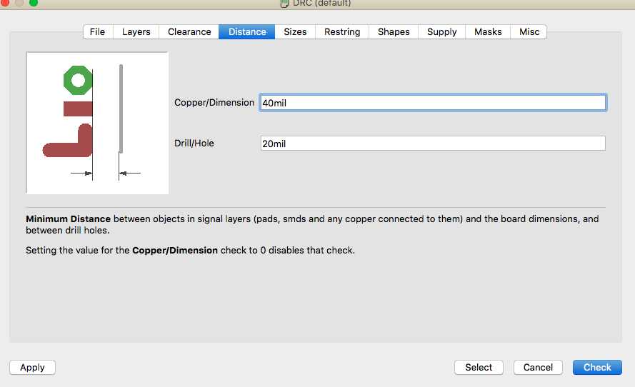
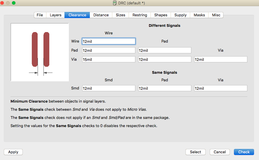
Design Rules Used
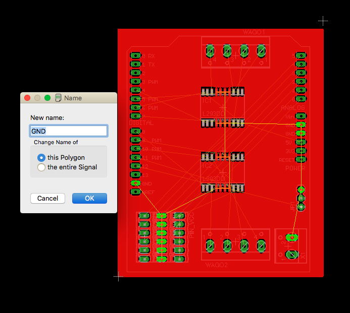
Creating a Ground Plane
I used the command line function to create a ground plane, by setting the name to GND.
Result
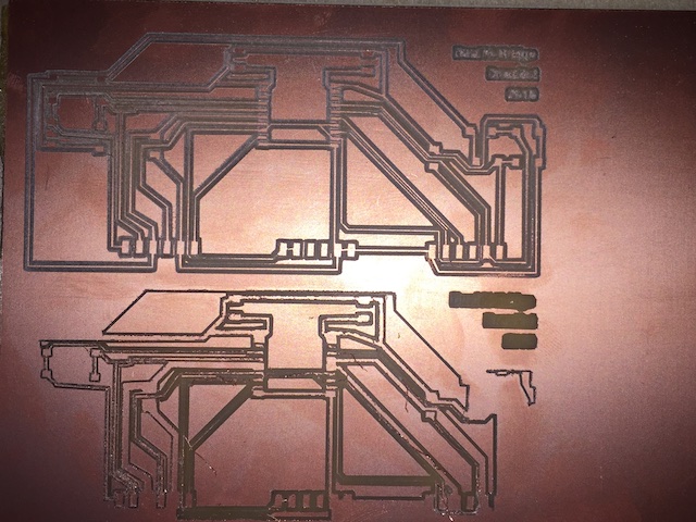
This PCB will be milled on dual copper plate. Here is the top, bottom side and view of both side combined.
Files for Phon Motorshield V 1.0
Motor shield Eagle files, Schematic and board, BOMReferences
- Using the L239D motor driver IC
- Allessandro Papaleo Motorshield based on Adafruit Motorshield
- L293DD datasheet
- L293DD datasheet
- Information on Stepper Motors: Types of Steppers
- Matching the Driver to the Stepper
- Informations on stepper Morors:University of Minesota