WEEK 8
EMBEDDED PROGRAMMING (WEEK 2 OF 2)
Assignment: Read a microcontroller data sheet Program your board to do something, with as many different programming languages and programming environments as possible
DETAILS
Reading the ATtiny44A Datasheet
Here is a summary of my experience in reading the ATtiny44A Datasheet (full version, 286 pages) I did not read it word by word, but more 'pin by pin', and 'pin function by pin function' using a lot the CTRL+F feature inside the PDF to search for the related subparts for any Searched Word (ex: RESET)
|
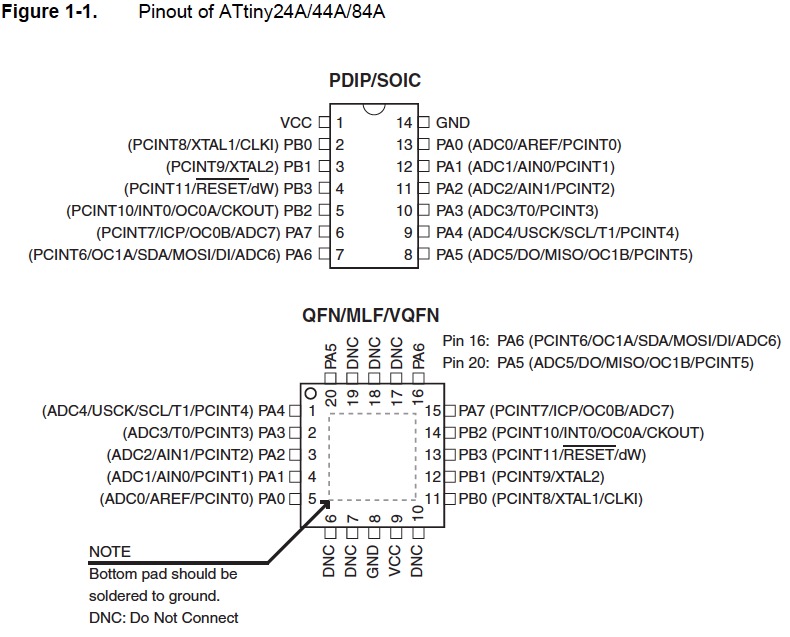
Schema of the PINsFor me the entry point of the document, from which I tried to understand the different functions available on each PIN
|
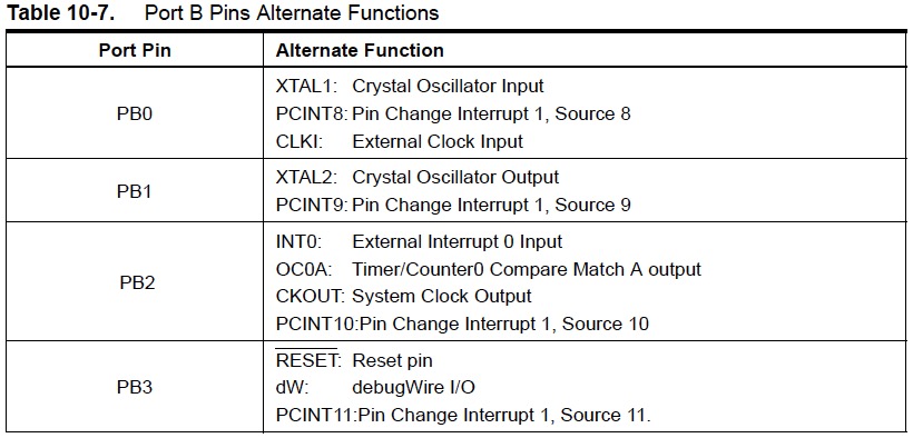
Table of the alternate functions for PIN PB[0,3]
|
|
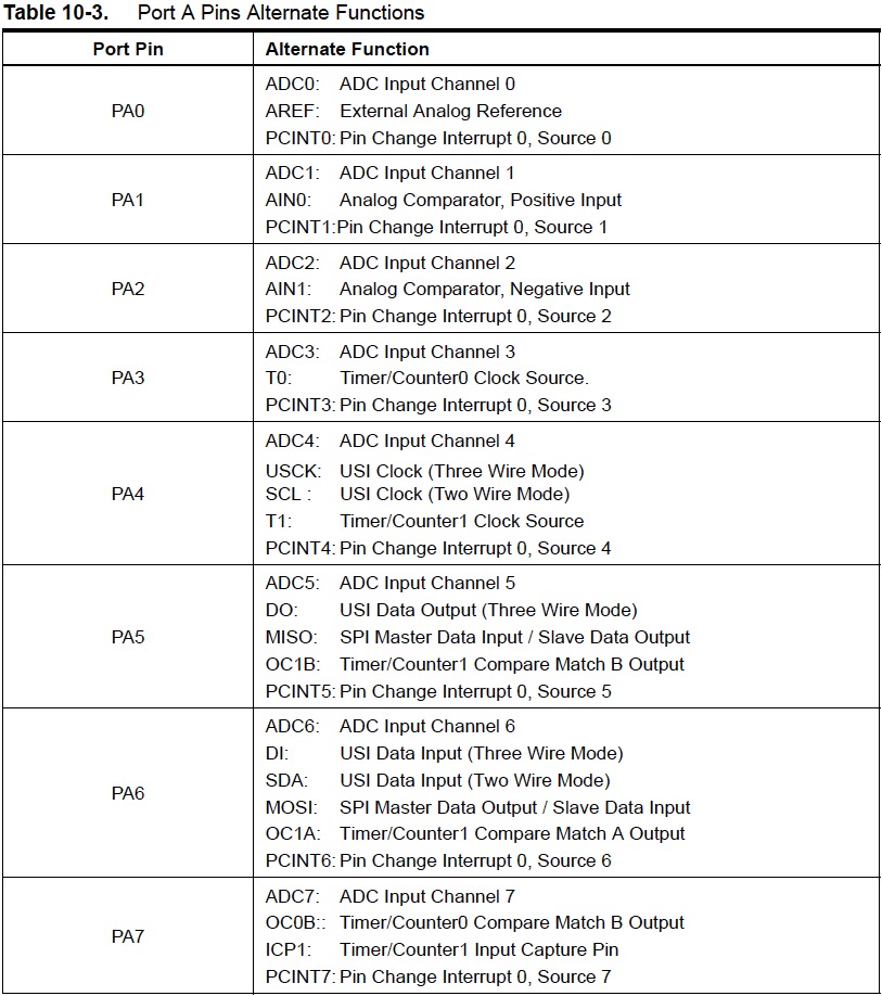
Table of the alternate functions for PIN PA[0,7]
|
Here is my understanding of the different functions: - ADC0 to ADC7: Analogic to Digital Converter, channels 0 to 7, INPUTS. It allows us to connect Analogic external periphericals to the MCU. Available on PIN PA[0,7]. - PCINT0 to PCINT11: Pin Change INTerrupt 0, sources 0 to 11. It allows us to generate an INTerrupt from an external peripherical. Available on PIN PA[0,7] and PB[0,3]. - INT0 and RESET: INT0 is an Internal INTerrupt, with highest priority than PCINT[0,11]. RESET is the top priority INTerrupt, with highest priority than INT0. - XTAL1 and XTAL2: It allows us to connect either a quartz crystal or a ceramic resonator to the MCU (INPUT and OUTPUT), if connected then it will be used as the On-chip Oscillator. - CLKI: It allows to connect an External Clock - WRITING IN PROGRESS ......... |
|
Schema of the relations (workflows) between the different functions/features
|
Some definition I found on Internet: - Interrupt INTerrupt Wikipedia definition - PWM: Pulse Width Modulator PWM Wikipedia definition - Other definitions coming soon ... |
Writing my first microcontroller programsusing Arduino IDEand a Arduino Starter Kit
Because I'm a beginner in discussing with a Microcontroller, I decided to do my first programs using the Arduino IDE and a Arduino Starter Kit
|
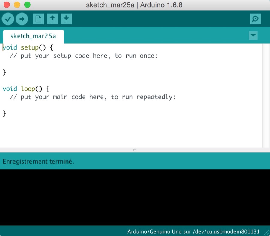
Installing Arduino IDEAnd launching it
|
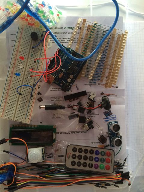
My Arduino Starter Kit from funduino.dea good package to start programing
|
|
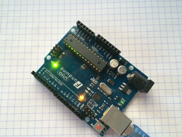
My first working program:switch on/off the onboard led of the Arduino Uno
|
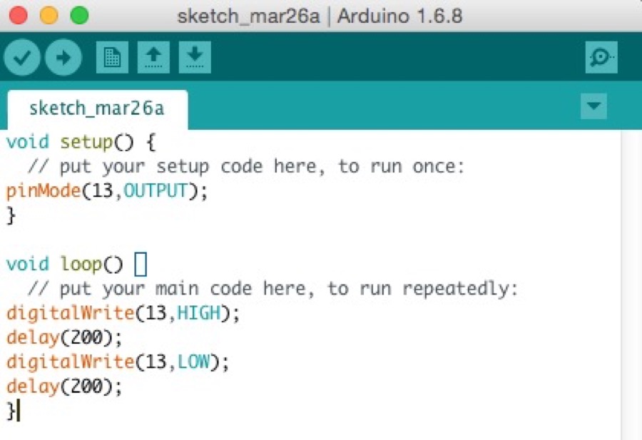
Here is the simple program that does it work
|
|
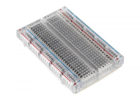
Then I needed to use the Breadboard to go furtherBut what is a Breadboard?
Here is the tutorial I read
|
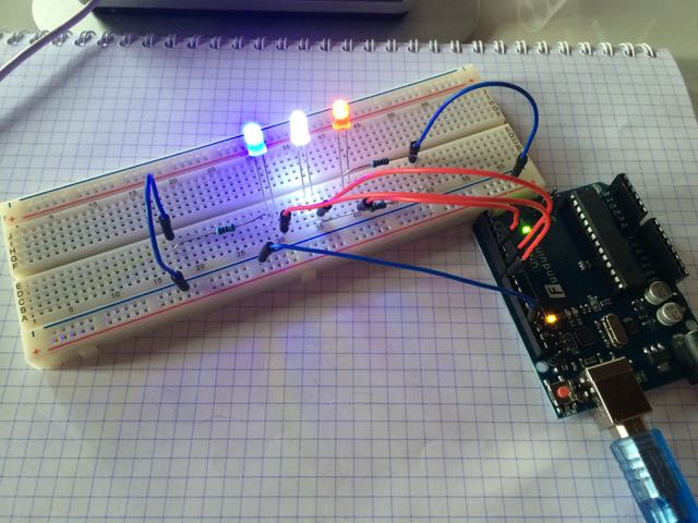
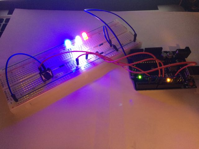
A more complex circuitusing 3 external leds: Blue/White/Red (FR flag colors)
|
|
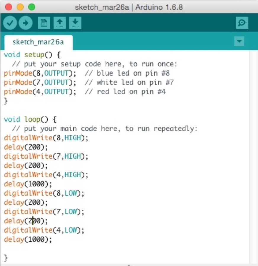
Here is the related program (first version)
|
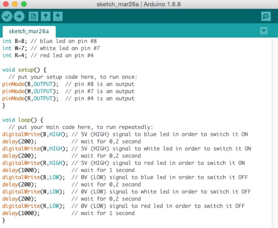
Here is the related program (2nd version)after optimizations (using variables at starting, adding comments)
|
|
A new circuit with a button to switch ON the leds
|
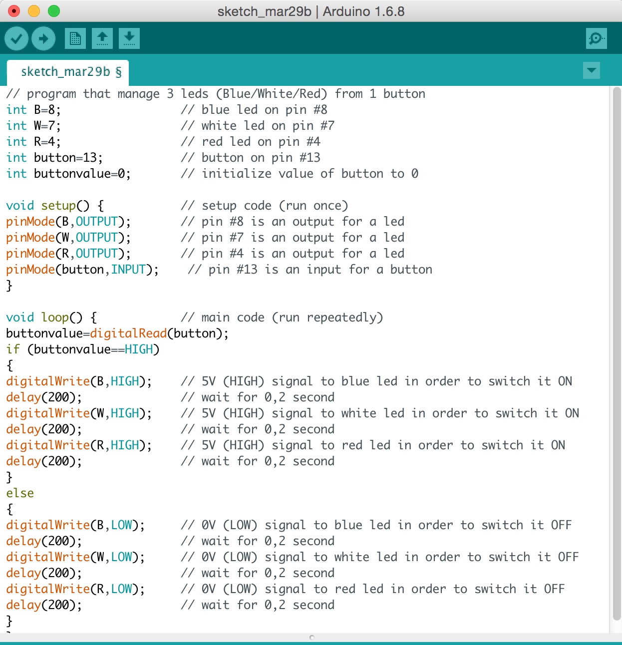
Here is the related programincluding the IF/THEN/ELSE condition on the button state
|
Writing programs and executing themon my Hello-World board
Now that I have more knowledge on programming with Arduino IDE and because my Hello-World board is milled and soldered (see week 6) I can start programming my own board!
|
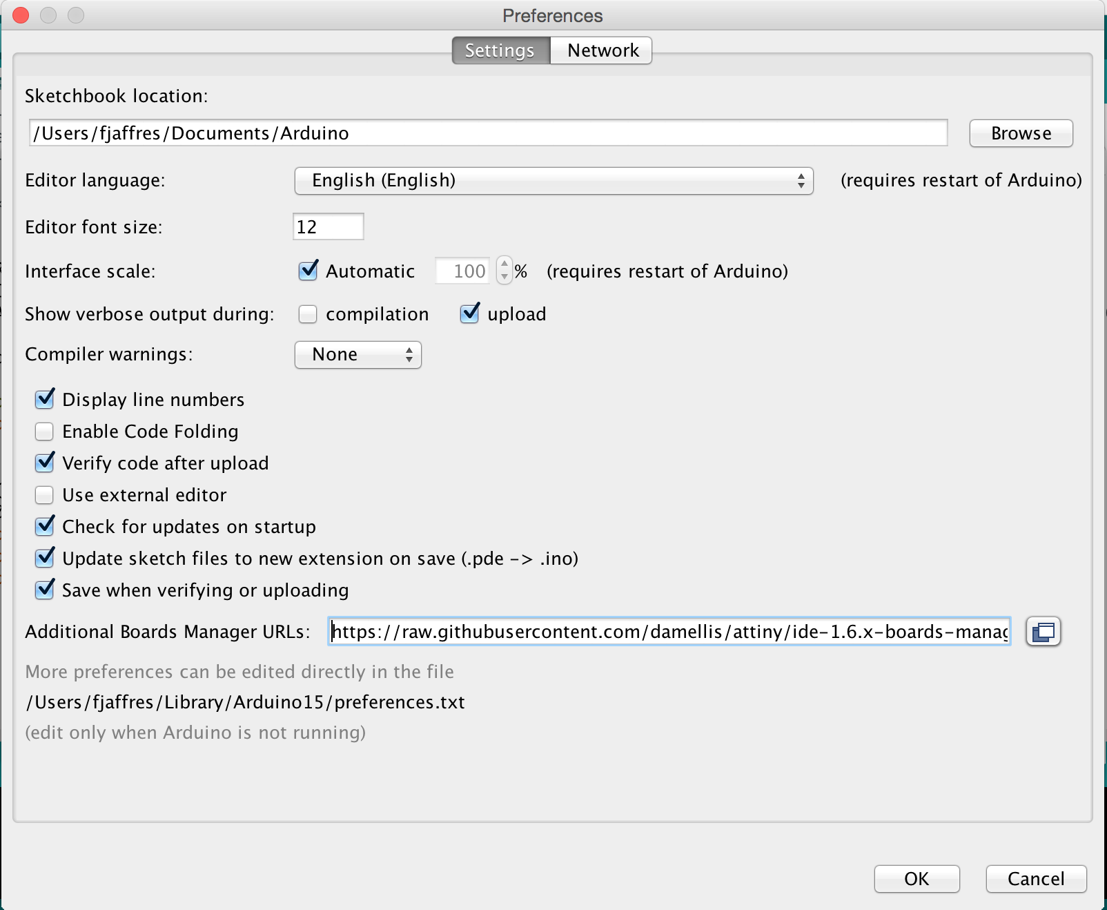
In arduino we need to install additional boards for AT Tinyby specifying URL
|
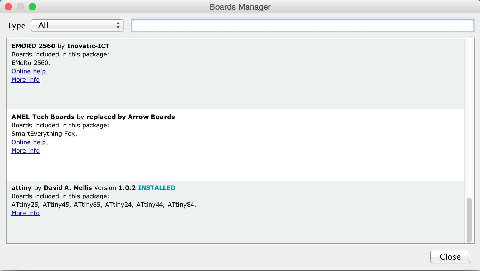
Then in the Board Managerwe have to install the AT Tiny package
|
|
Now we install the ArduinoISP program to Arduino Unoto use it as a ISP programmer
|
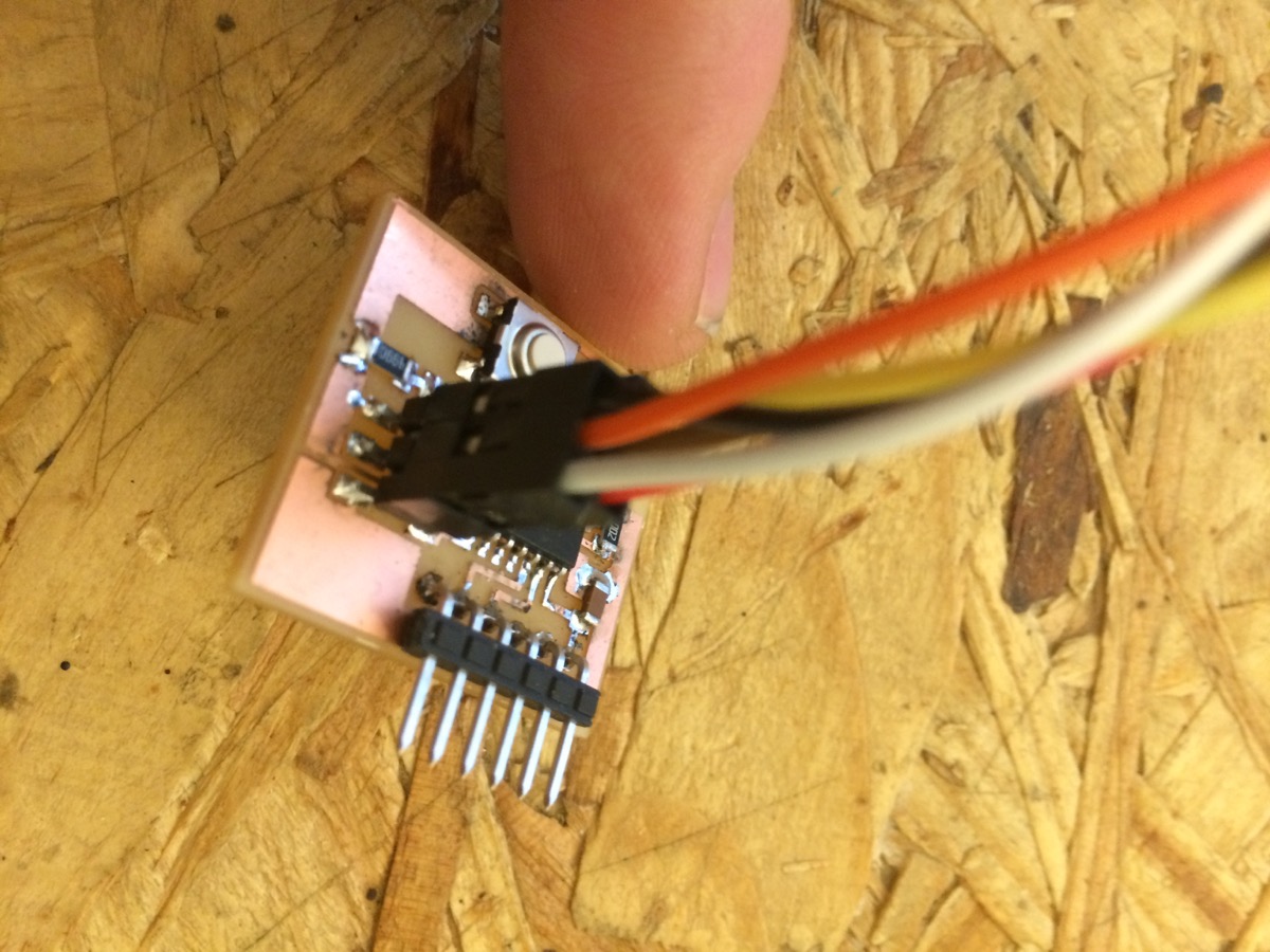
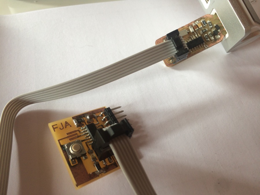
wire connections on Hello-World Board side
|
|
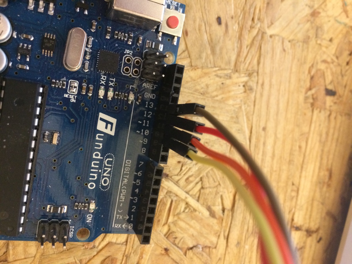
wire connections on Arduino Uno side
|
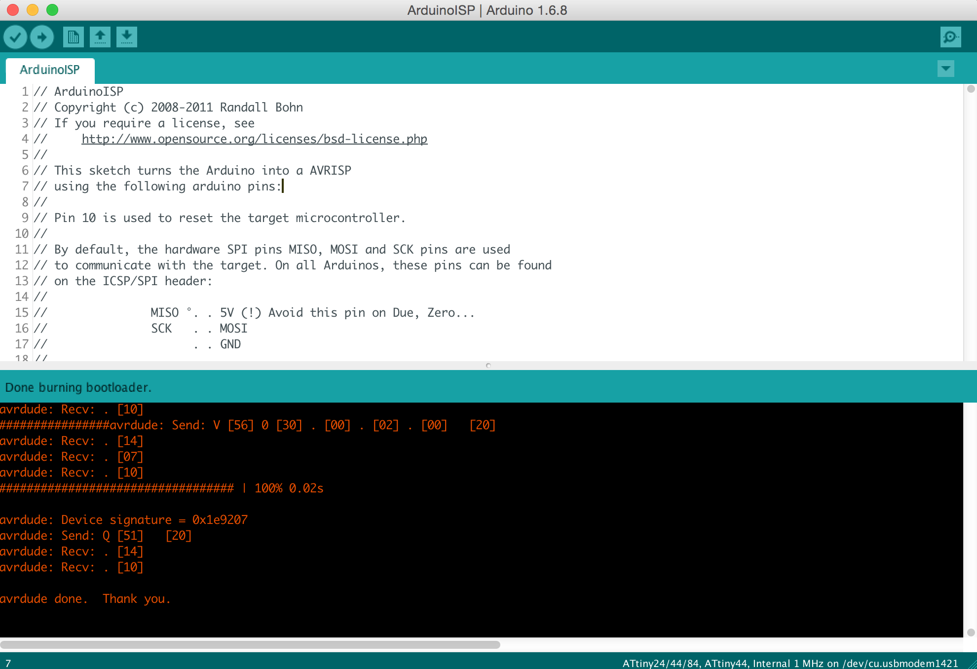
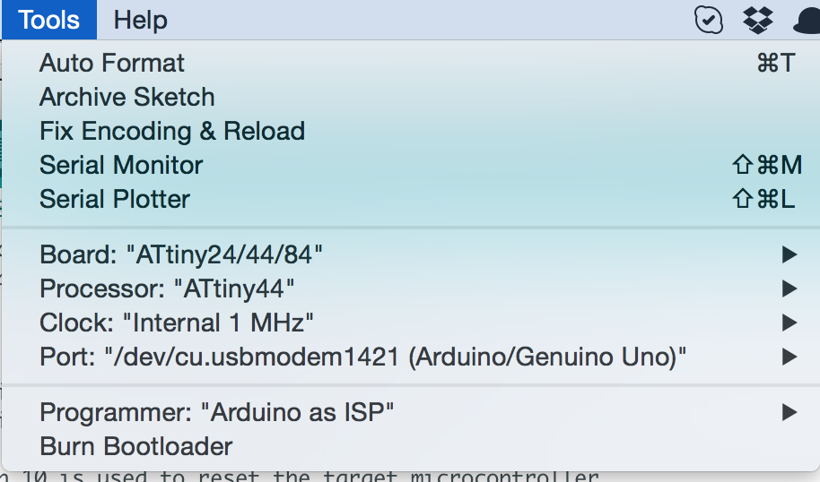
Burn Bootloader with the good settingson the AT Tiny
|
|
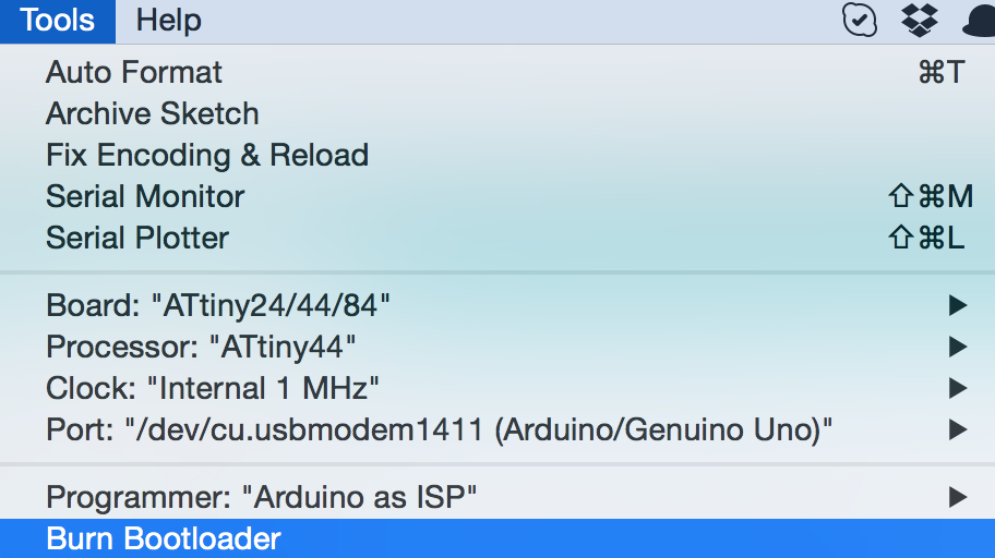
Selecting the good Board/Processor/Clock/Port/Programmer
|
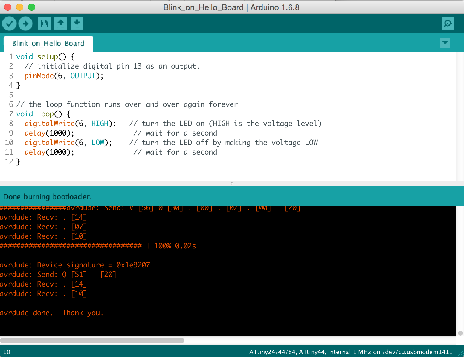
First Sketch: blink on the Hello-World boardUploaded Using Programmer
|
|
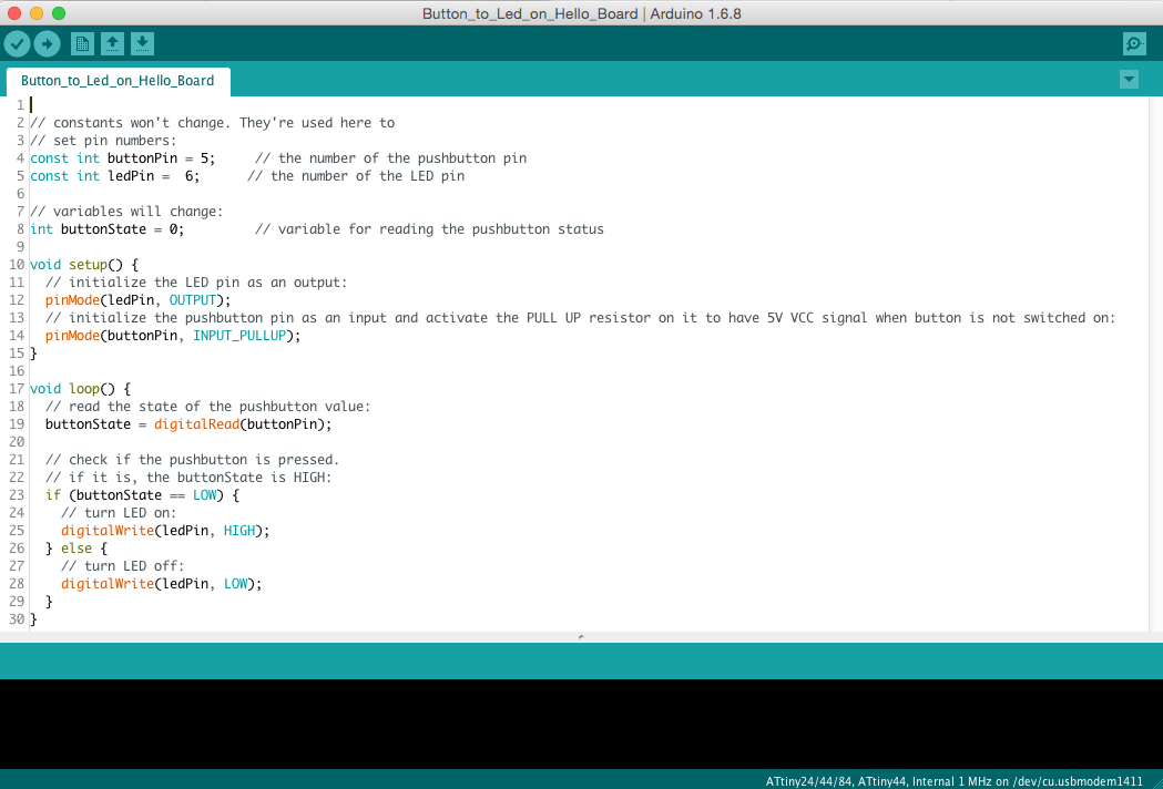
Second Sketch: button to led on the Hello-World boardUploaded Using Programmer
|
Video
2ND ROUND
Programming my Hello Board using my FabISP
During the 1st Evaluation Round, I was finally able to programm my FabISP, but it was really at the end. During the 2nd Evaluation Round, I only used my FabISP to burn boards, and I used either FabISP or FTDI to program boards.. Below, you will see how I burned and programmed my Hello World board with my FabISP
|
My FabISP connected to my Hello Board
|
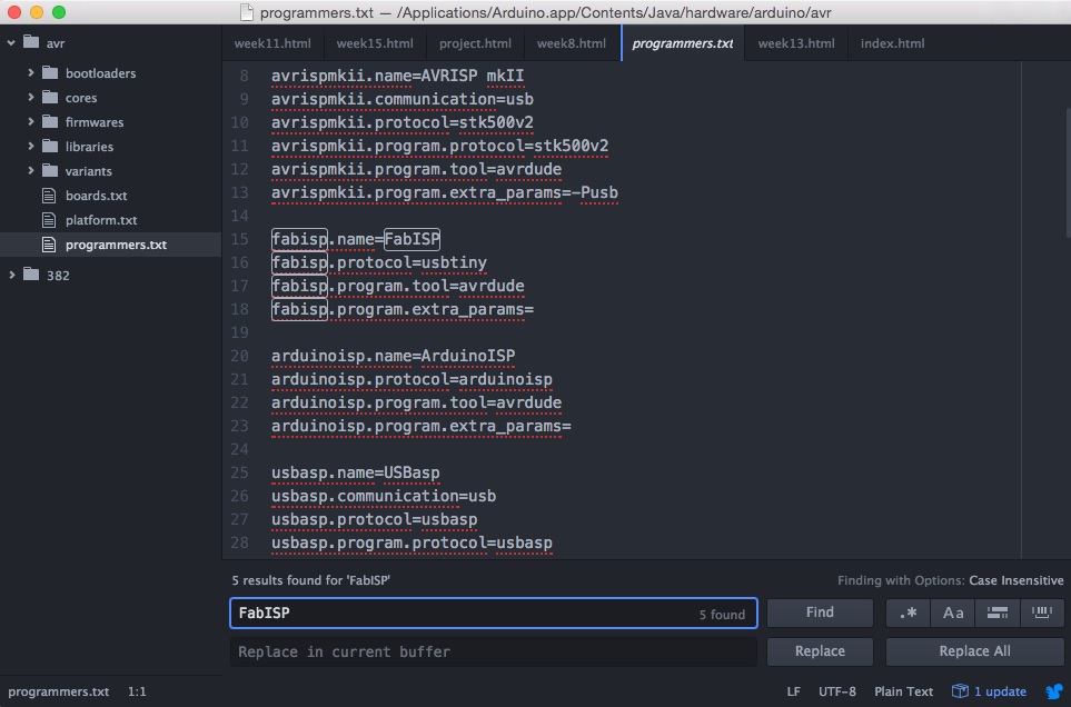
Using the FabISP as a programmer inside Arduino IDE.Some modifications were required inside file /Applications/Arduino.app/Contents/Java/hardware/arduino/avr/programmers.txt in order to recognize my FabISP inside Arduino IDE.
|
|
Then burning my board (ATtiny44, 1Mhz internal) using my FabISP First trying to apply same programs as I did in last June, but IT DID NOT WORK! I imagined that it can be related to my Hello Board, so I need to redo it from scratch! In the same time, in the interval I did a lot of changes: - I updated avrdude version to finalize my FabISP (it was one of my last tasks in previous round) - I just updated version of Arduino IDE - I updated version of AT core librairies So finally decided to switch to Input Devices todo, and come back to this topic later |
After working on Input Device, during when I discovered issues with standard Arduino IDE command (support for ATtiny) I came back to the Hello Board, and tried to program it with avr/io library (see week 11 2nd round for more details) I also found interesting code from some Niel's programms, like in this one And results were better ;-) |
|
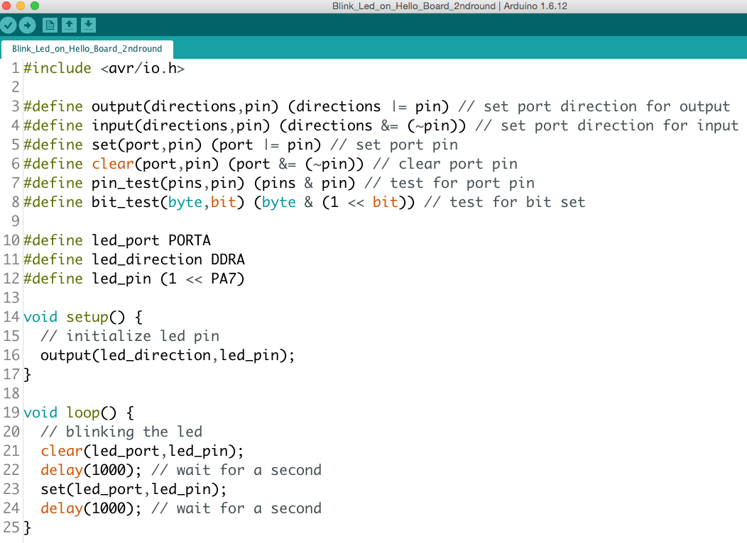
Here is the Blink Led programm.See program in the ouputs at the top of the page.See following video...
|
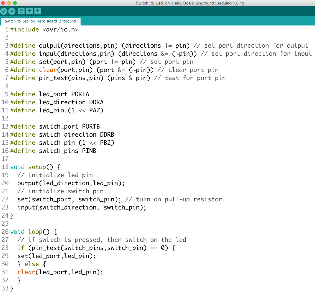
Using the same library.Here is the Press Button programmSee program in the ouputs at the top of the page.See following video...
|
Video
Here are the 2 programs working! :-)
In this video: burning the Hello Board with my FabISP,then running the 2 programs after loading them with my FabISP