WEEK 15
NETWORKING AND COMMUNICATIONS
Assignment: Design and build a wired and/or wireless network connecting at least two processors
What I did: I connected 2 Satshakit boards together via a I2C wired network. I made them communicate via the I2C network (master to slave), and I got the output of this communication on the Serial port of the slave using the Rx pin of a FTDI cable, that I displayed in the serial monitor.
I did it in 3 steps: - step 1: programming the I2C Master (First Satshakit), and test it with Arduino Uno as I2C Slave,collecting the output of communication on the serial of the Arduino Uno directly - step 2: programming the I2C Slave (Second Satshakit), and test it with Arduino Uno as I2C master,collecting the output of communication on the Serial of a FTDI cable connected to the serial ports of the Satshakit - step 3: connect the 2 Satshakit together via the 2 I2C pins (A4toA4 and A5toA5, which are SCL and SDA), and collect the output of communication on the Serial of a FTDI cable connected to the serial ports of the Satshakit Slave
DETAILS
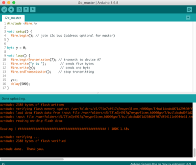
STEP 1: Programming First Satshakit as the I2C Master and testing it with Arduino Uno as I2C slave
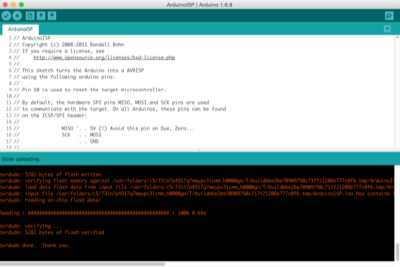
The Arduino Uno is used as a ISP programmer (because I was not able to push programs directly to my Satshakits) so we have to push ArduinoISP sketch to Arduino Uno, and then use "Upload Using Programmer" feature to push programm on Satshakit
|
Pushing ArduinoISP sketch to Arduino Unoso that I can use it as Programmer
|
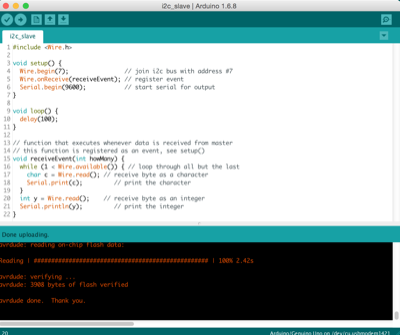
Pusching I2C master program to First Satshakit
|
|
Now pusching I2C slave program to Arduino Uno
|
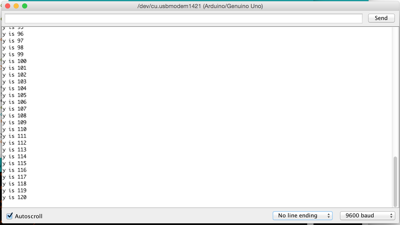
Here is the output of communication on the serial monitor connected to Arduino Uno (I2C Slave)
|
|
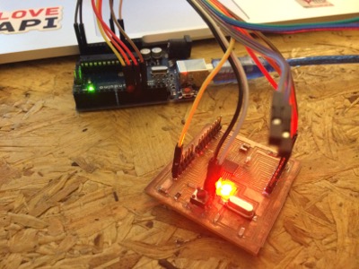
First Satshakit and Arduino Uno connected (for both ISP programmer step, and I2C step, as it is not using same pins)
|
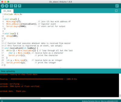
STEP 2: Programming Second Satshakit as the I2C Slave and testing it with Arduino Uno as I2C master
Doing the same tasks but roles master/slave are inversed between Satshakit and Arduino Uno
|
Pushing the Slave programm the the second Satshakit
|
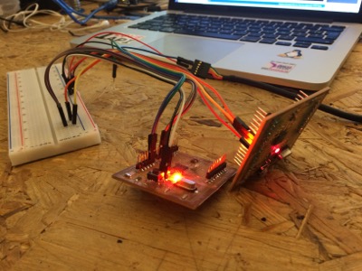
Second Satshakit connected to Arduino Uno during this second step
|
STEP 3: Connecting the 2 Satshakits togetherthat communicate via I2C network
No that programs are uploaded on both Satshakits, and tested with the Arduino Uno I can connect Satshakit boards together, and validate that it still works fine, and it is the case!
|
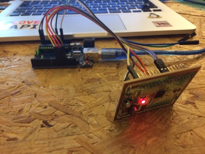
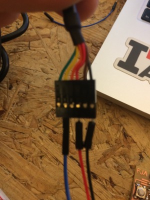
The 2 Satshakit are connected together via 2 wires (A4toA4, A5toA5) for the I2C communication. NB: there is no Arduino at all in the final validation schema.
|
Yhe power is provided to the 2 boards using the power of the FTDI cable and I have connected the Rx pin of the FTDI cable to the Satshakit Slave in order to get the output of the master/slave communication
|
Video
2ND ROUND
Doing more Network and Communication
I2C network using Niel's boards
In order to improve my knowledge in network and communication, I decided to redo the Niel's I2C boards. All outputs files and programs are above in the summary table at the top of the page.
|
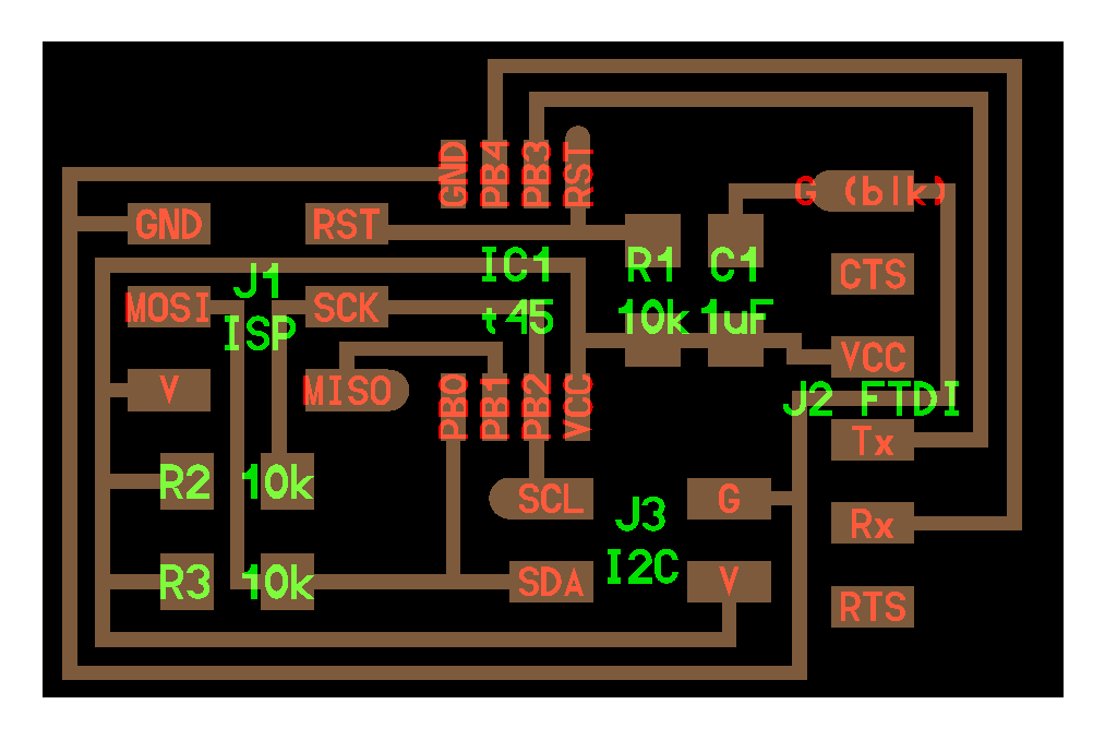
Here is the Neil's original I2C bridge (master) board. See the related .png and .rml files in the ouputs at the top of the page.
|
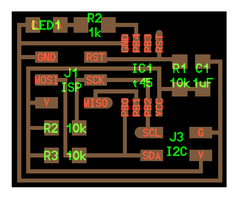
Here is the Neil's original I2C node (slave) board. See the related .png and .rml files in the ouputs at the top of the page.
|
|
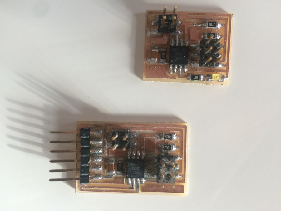
Here are my boards, after milling and soldering
|
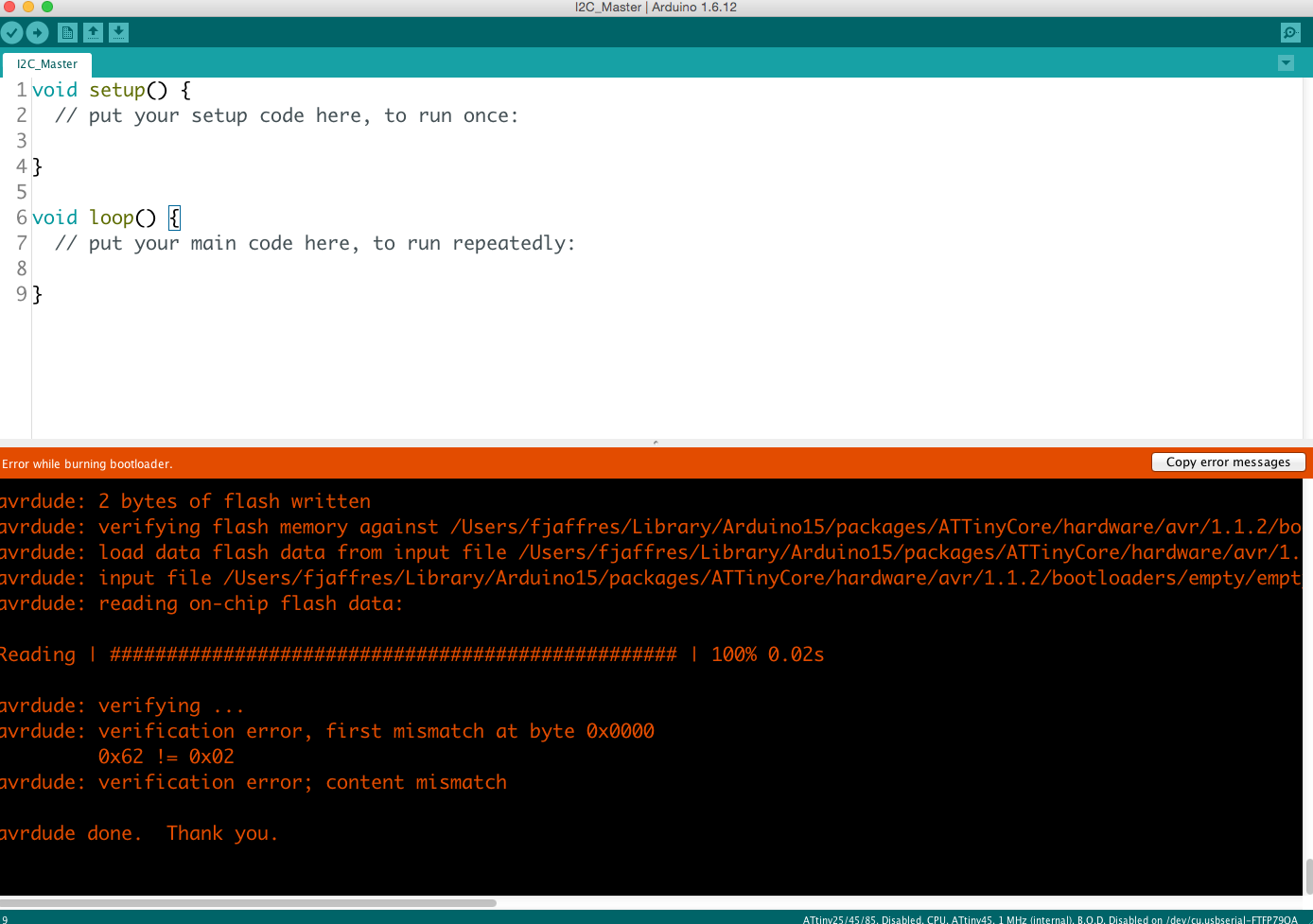
Trying to burn the Board from my Arduino IDEIt is not working
|
|
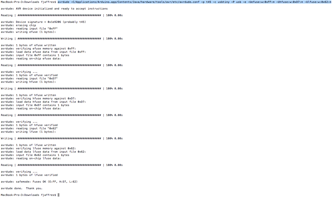
To solve this issue (that I already encountered in the past and which is probably related to the version of my Arduino IDE, v1.6.12, last version)I burned using the following command in my command line: "avrdude -C/Applications/Arduino.app/Contents/Java/hardware/tools/avr/etc/avrdude.conf -p t45 -c usbtiny -P usb -e -Uefuse:w:0xFF:m -Uhfuse:w:0xD7:m -Ulfuse:w:0x62:m"which is just a variant of the command line that Arduino IDE is lauching (but using a different avrdude, and a different avrdude.conf)
|
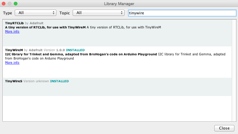
Now that both I2C master and node are burned I can start programming on thembut before I need to install a libraries TinyWireM (from Adafruit) and TinyWireS (from http://playground.arduino.cc/Code/USIi2c) that manage I2C, also I added a Board Manager from https://github.com/SpenceKonde/ATTinyCore
|
|
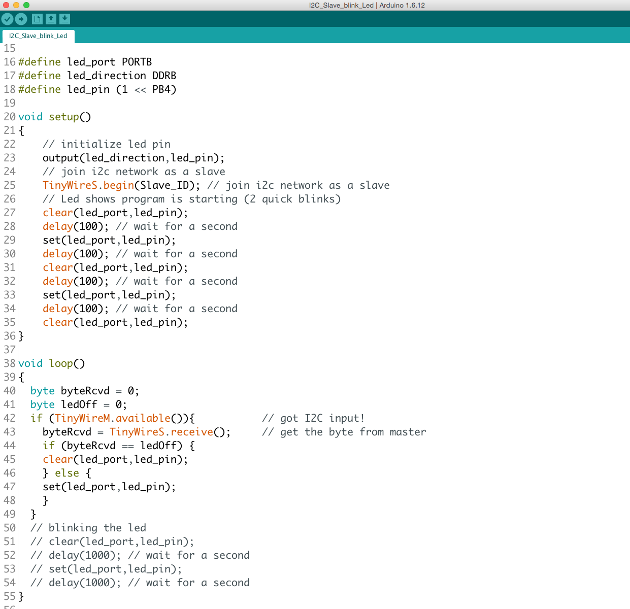
First I did the programm for the SlaveIn a very first time it was just a Led blinking to check if card is wworking finethen I added logic of receiveing a transmission from I2C master
|
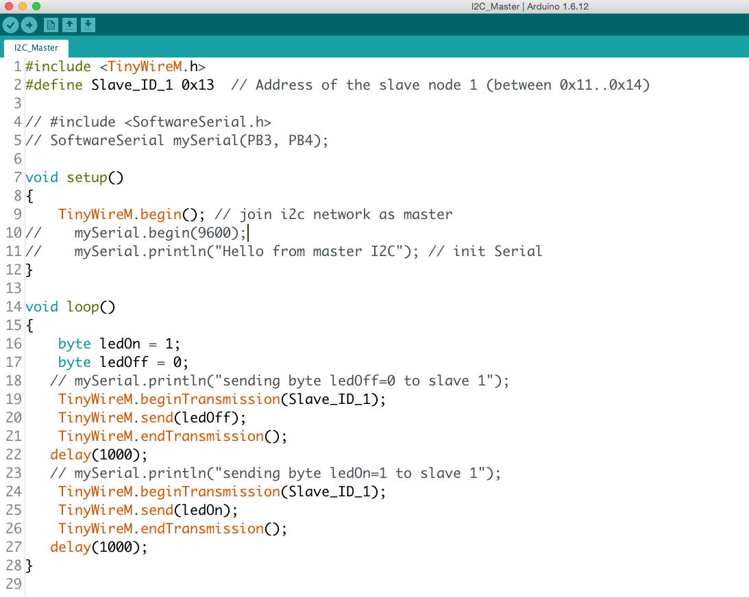
Then I did the programm for the masterAt the starting I integrated a software serial logic to see what Master is doing in the loop (in the Serial monitor)But it was consuming too much ressourcesSo I disbaled this software serial logic
|
|
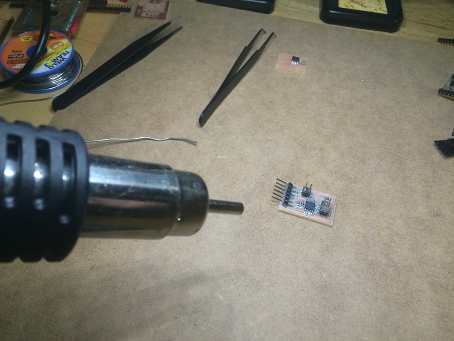
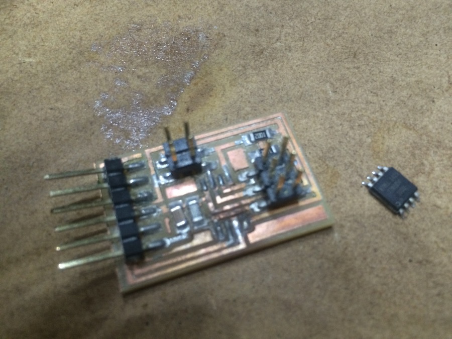
I first pushed my programm to the slaveThen I pushed my programm to the MasterBut I connected I2C network before doing this, and looks like I damaged my ATtinyNo more possible to programm it, Burn it, or to Read it (via command "avrdude -v -p t45 -c usbtiny -P usb -U flash:r:test.hex:i")So no other choice than changing the At tiny on the board :-(Unsoldering it with my "heating pistol" (first time I use it)
|
Now re soldering it
|
|
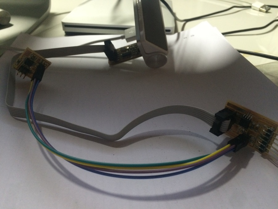
Then I was able to push programms to Master againAnd I got the resultMy program is working, but looks like my slave is not catching each value from masterso the frequence of blinking is not the one specified b ythe masterprobably a communication issue, need to work on it more, perhaps playing with Pullup Resistor values, I read a bit about it ...
|
Video
Here is the program running
The Led is blinking on the slave node, but not at the frequence defined on the masterprobably an issue on communication between both nodebut it is blinking, so slave receive data from master and blink on the condition defined
Designing my own I2C node board
I also worked on designing a custom I2C node board, dedicated fo the connection of a Digital Input or Output (1 pin, 1 GND, 1VCC)
|
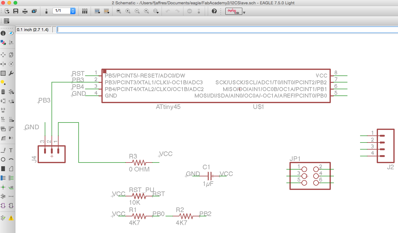
Here is the Eagle schematic view of the board.See the related .sch file in the ouputs at the top of the page.
|
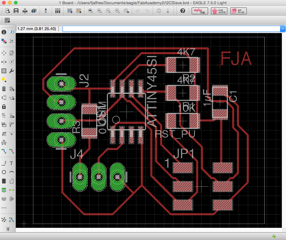
And here is the Eagle board view of the board.See the related .brd file in the ouputs at the top of the page.
|
|
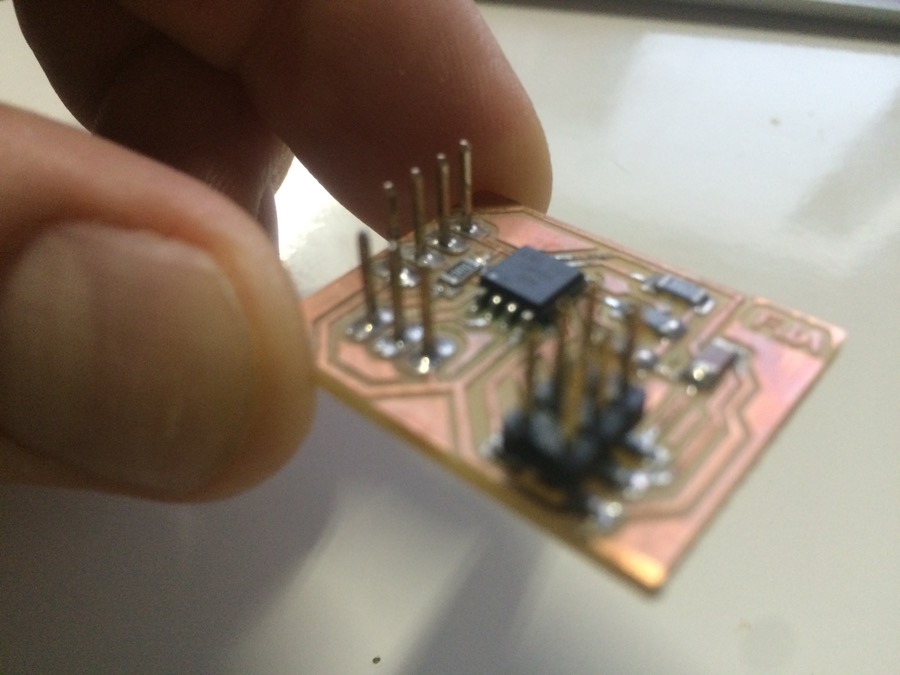
Here is the board, after milling and soldering
|