Thermal study
The first step is to check the feasibility, and advantage, of having the freezer nested into the cooler. We therefore need to calculate the heat power involved in the process.
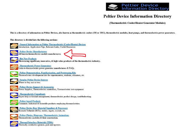
There are different sources which give information about peltier devices and support the necessary calculation. I first surfed through a very well made blog on the subject Peltier Device Information Directory.
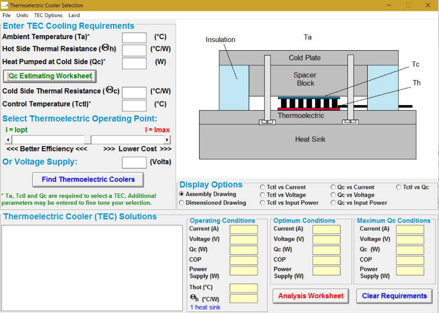
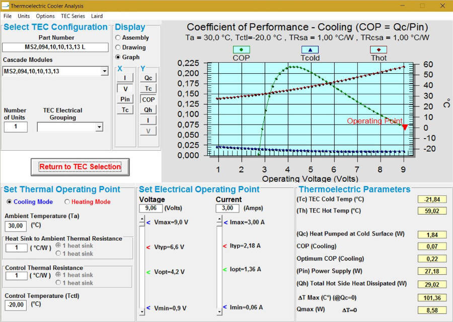
From there, I found a company which makes available an online tool to get a first idea of the heat energy that must be drawn from cooler and freezer in a stade stade operation:
TE Technology, Inc. - Cooling Assembly and Heat Load Calculator.

This is the data needed:volume of freezer: the freezer size should be sufficient for four tube racks, stacked two by two.
The available volume should be mm 131x210x110 = 3.0261 dm3
The cooler size requirements are mm 291x300x160 = 13.968 dm3
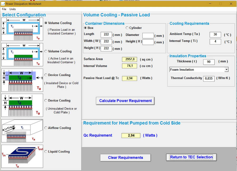
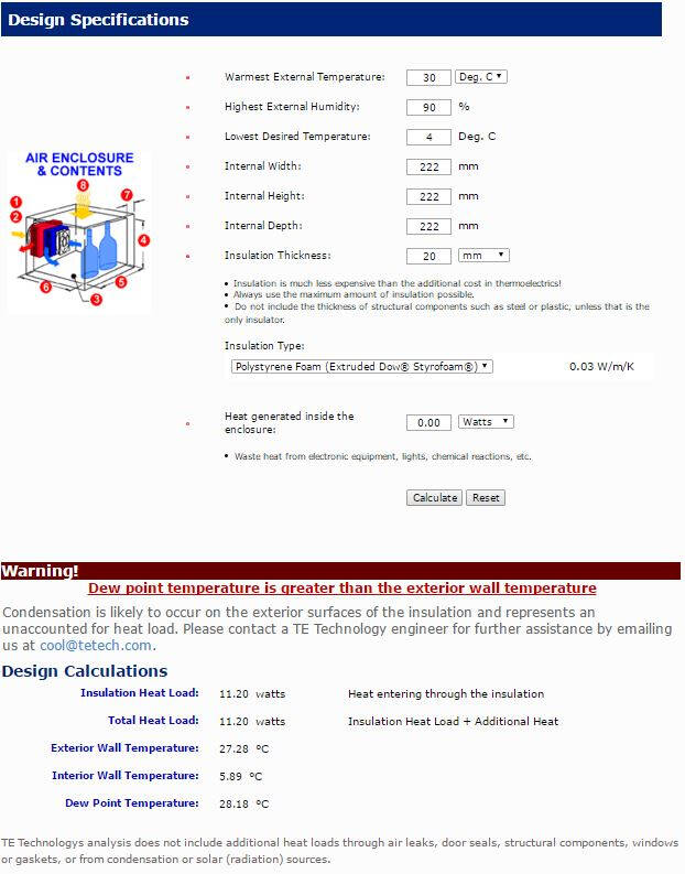
Effective volume of cooler, if the freezer is embedded: 13.968-3.0261 = 10.9419 dm3 which is equivalent, for calculation purposes, to a cube of mm 222x222x222.
When using the online tool it is immediately clear that insulation thickness greatly influences the heat energy that must be pumped out by the cooling system and, in turn, the type of peltier element. It is necessary to run different iterations to set the correct system design.
Let's quickly draw two design scenario:
- Individual cooler and freezer;
- Freezer nested into cooler;
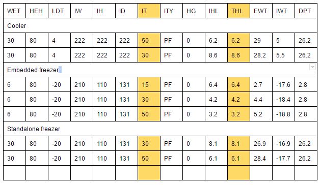
WET= warmest external temperature (°C)
HEH= highest external humidity (%)
LDT= lowest desired temperature
IW= internal width (mm)
IH= internal height
ID= internal depth
IT= insulation thickness
ITY= insulation type
HG= heat generated inside the enclosure (W)
IHL= insulation heat load (W)
THL= total heat load
EWT= exterior wall temperature
IWT= interior wall temperature
DPT= dew point temperature
PF= polyurethane foam
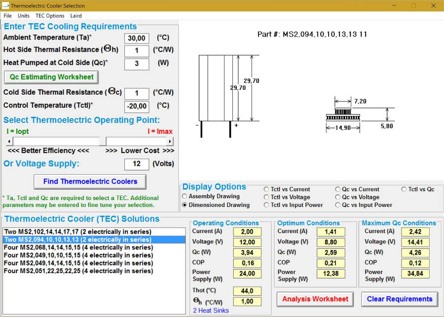
Power requirements cooler and freezer: 6.2 + 6.1 = 12.3 W
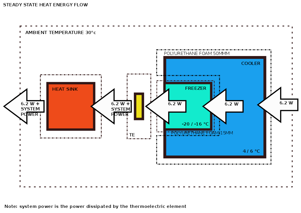
Power requirements cooler with embedded freezer: 6.2 W.
The second solution halves the power requirements. Moreover, it only needs a single thermoelectric block instead of two.
In this case, to get a correct thermal balance, the heat energy flowing through the cooler must be the same as the thermal energy flowing through the freezer and through the peltier element. The freezer insulation must be adjusted accordingly. However, the final insulation thickness and the corresponding thermal power, will be set with the selection of the peltier element.
The thermal balance scheme is the following: