The machine
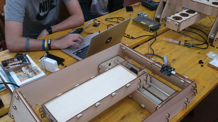
The machine we decided to build is a pick and place that can create a mosaic with tesserae starting from an image. The canvas is made of two centimeters square tesserae arranged in a 100 by 100 matrix.
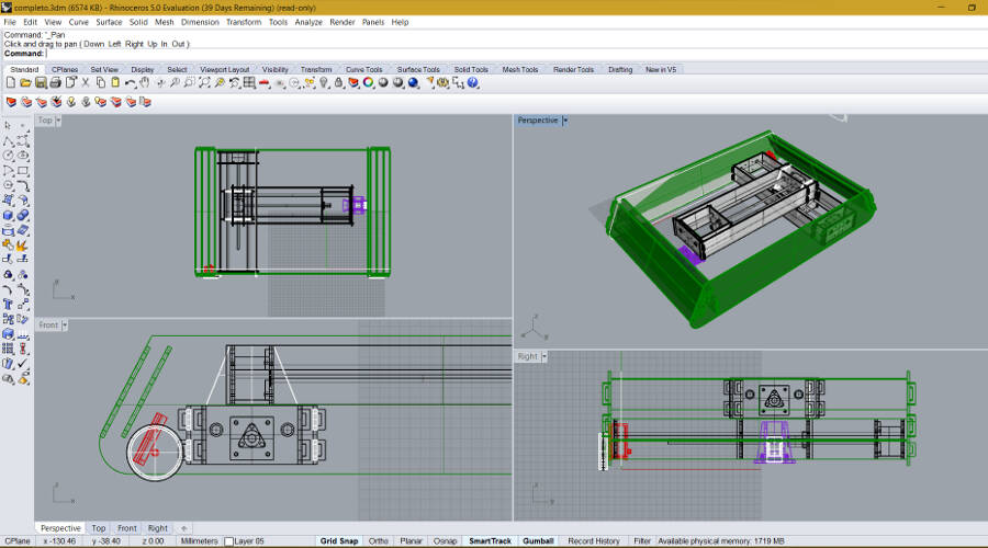
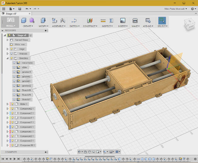
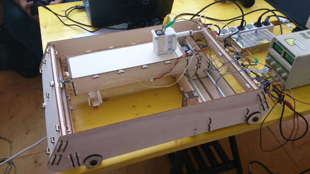
I was in charge of fabricating the stages for the two axes and, together with the student Francesco Filpa, the system to drive the vacuum syringe. This is the machine overview.
Stages design
The stages were inspired from the Modular Machines that Make: Cardboard CNC project. We just decided to make them in plywood in order to easily join two stages by modifying some of the component parts.
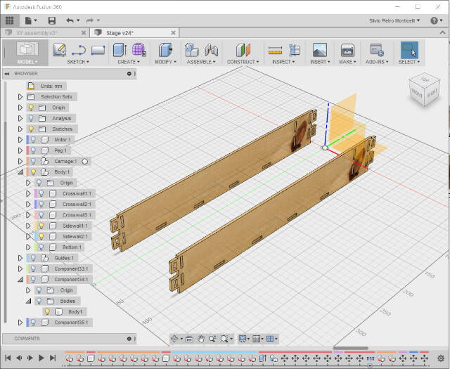
I made the design using Fusion360.
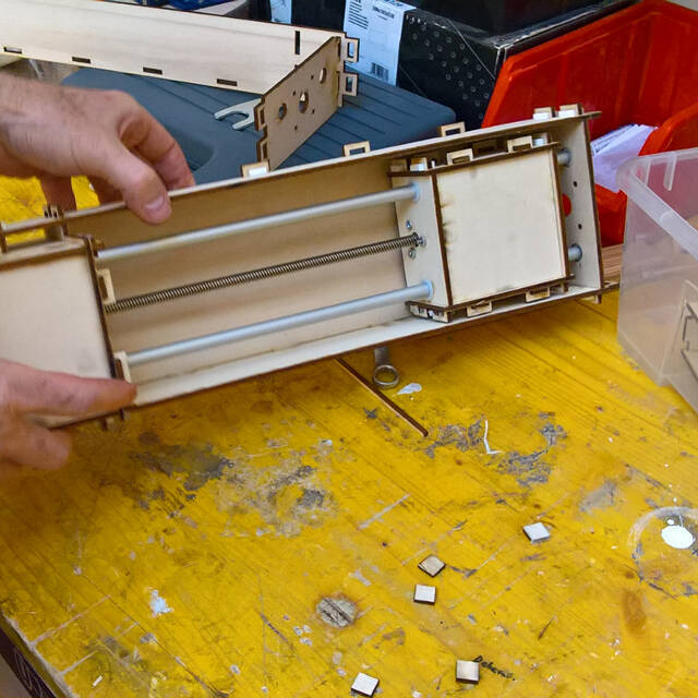
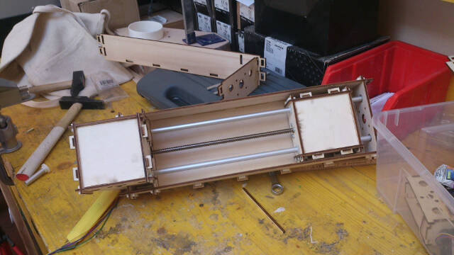
The stage is made up of:
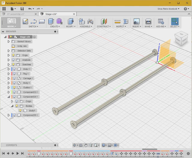
- Motor with feed screw and sliding bolt
- Guides
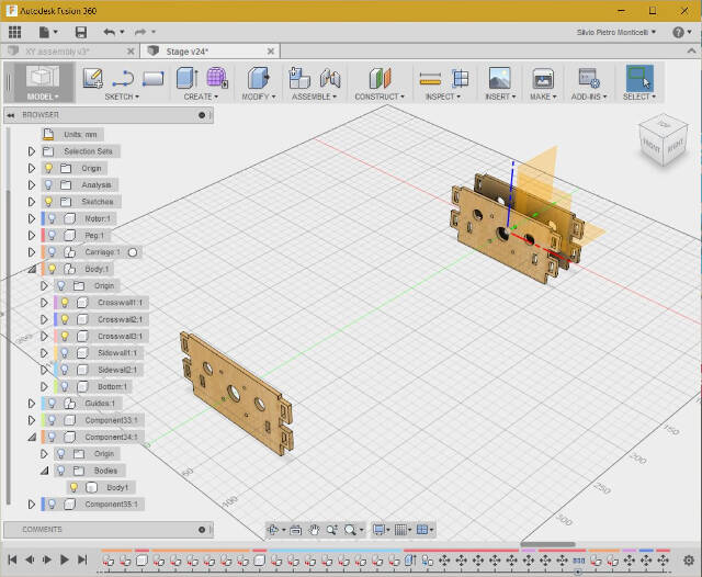
- Cross sidewalls
- Longitudinal sidewalls
- Carriage box
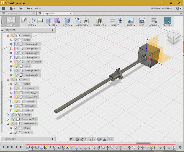
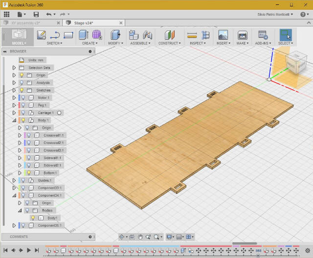
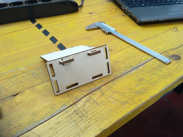
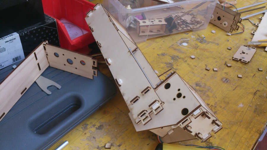
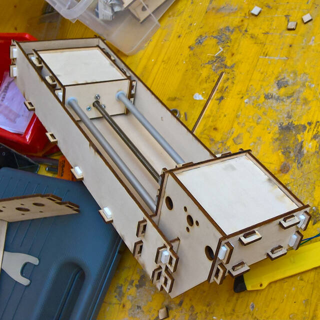
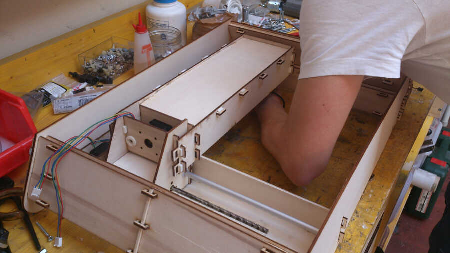
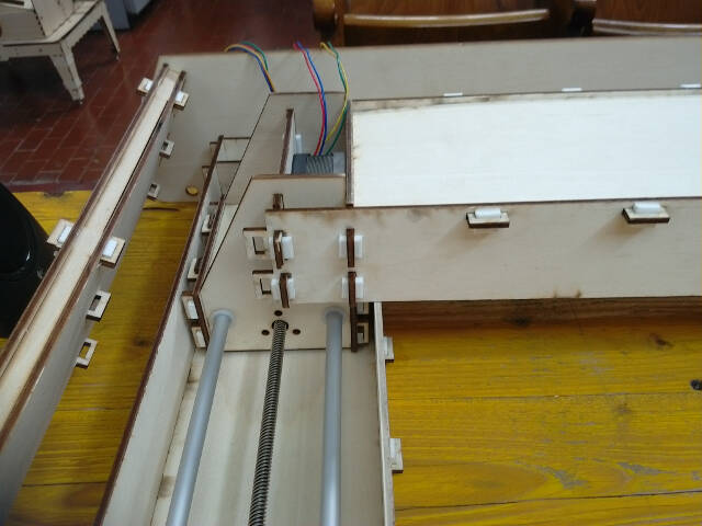
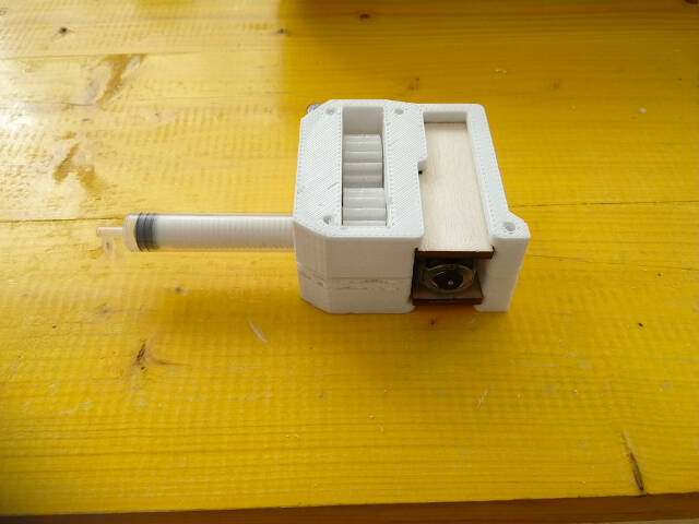
Here is the complete stage.
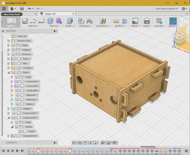
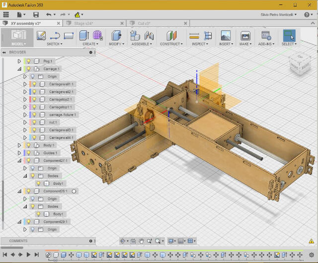
In order to join two stages I modified three sidewalls of the carriage box which become part of the second stage structure.
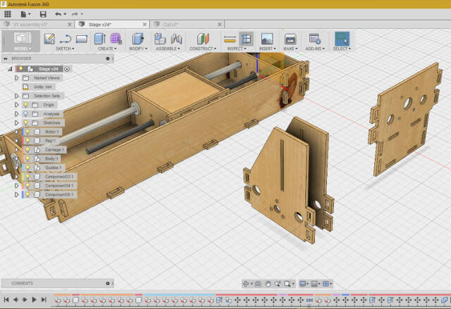
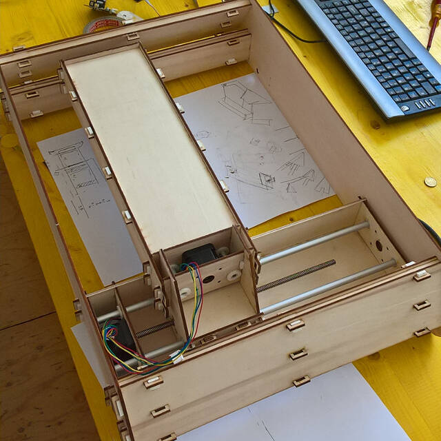
This the link to the design history and here is the full assembly (without 2nd stage bottom).
Stages production
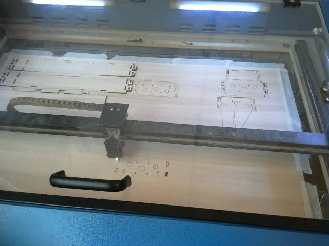
I machined the components on the laser cutter setting the plywood board on Fusion360 similiarly to what I did in the Computer Controlled Machining lecture.
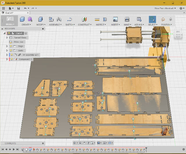
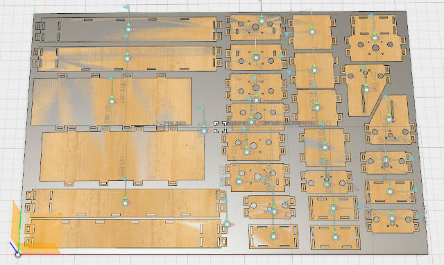
I then imported the IGES file in Rhinoceros and, after selecting all the components, converted them in a 2D design using the Make 2D Drawing functionality.
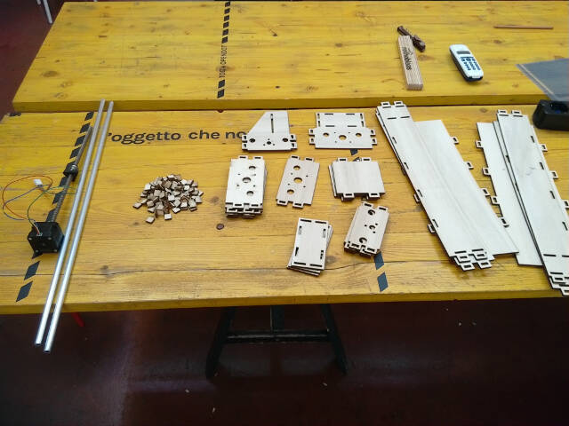
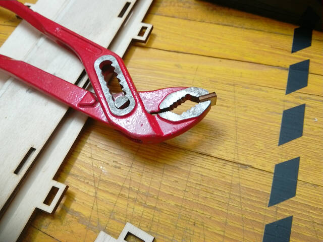
The pegs I used to assemble the parts were sometimes too thick. Actually, I did not take tolerances into account. Anyway, compressing them a little with a wrench helped bring them back to the correct size.
Gear assembly for vacuum syringe
Discussing with teammate Francesco Filpa the idea of driving the vacuum syringe with a gear assembly, and picking up from his study, I suggested making a more stable structure. I was also interested testing the ability of 3D printing to deal with “precision” mechanical assemblies.
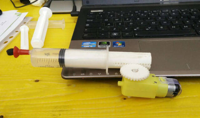
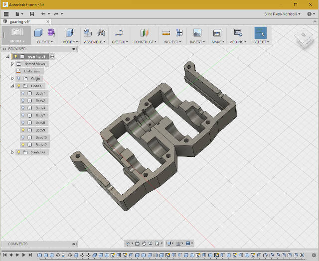
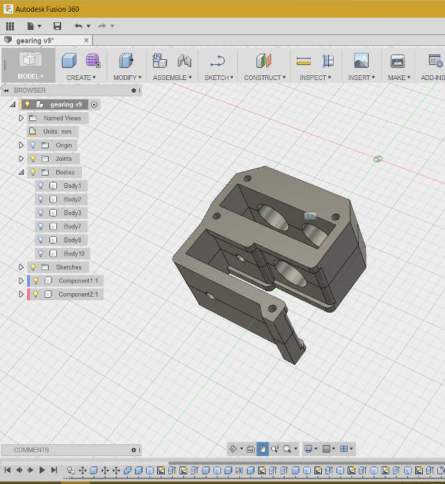
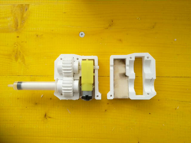
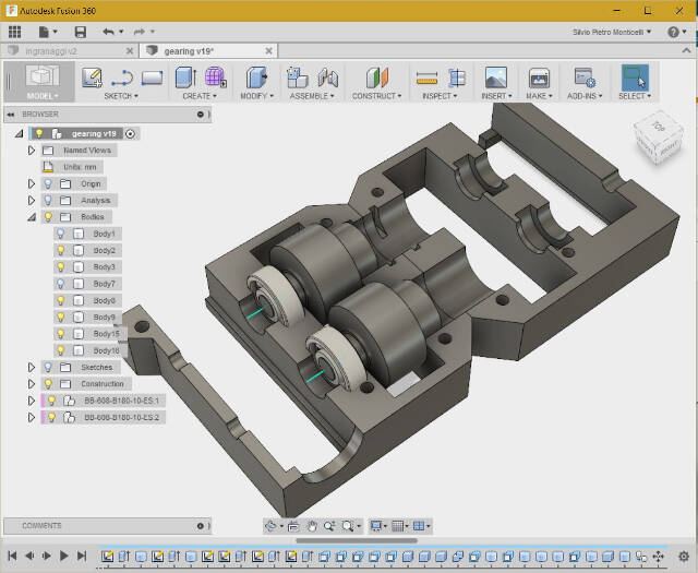
I designed the gear box (Fusion360) with two meshing gears: one driven by the DC motor and the second one driving the syringe worm gear piston. The gearbox is made up of two matching and bolted halves.
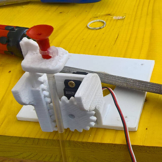
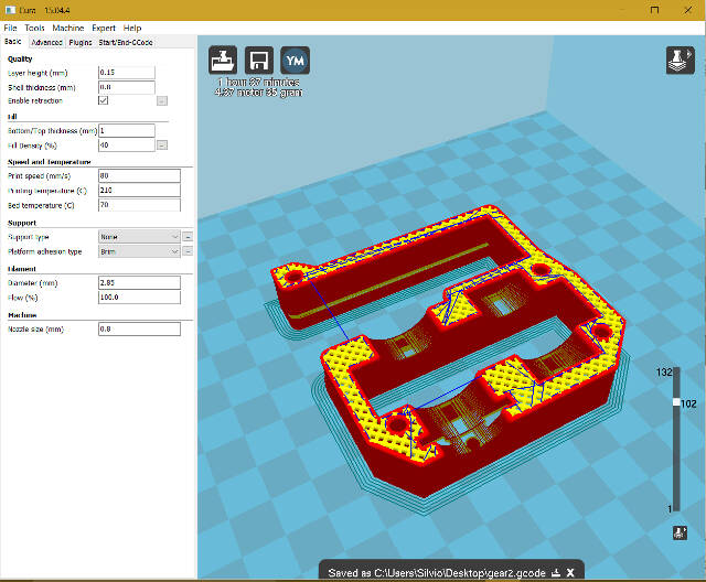
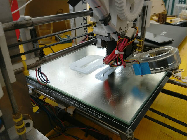
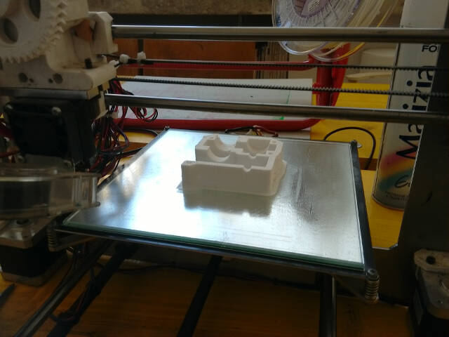
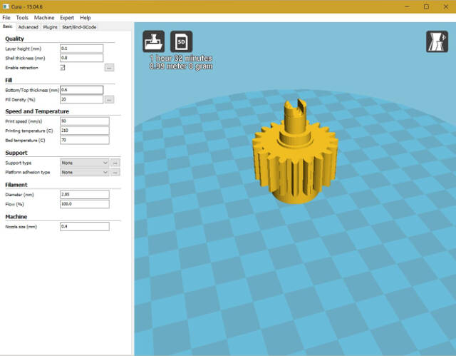
Parts where 3D printed (via Cura software) on the RepRap Prusa i3 and the Delta Wasp 20x40.
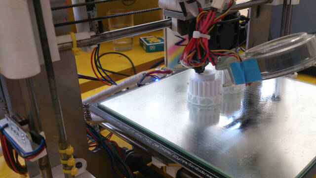
Once the group assembled I noticed some resistance to rotation which could be easily overcome by hand but not by the available DC motor. I tried adjusting the assembly with a file to have the system working through the machine presentation but unfortunately I could not get the syringe piston to move smoothly and suck the tiles.
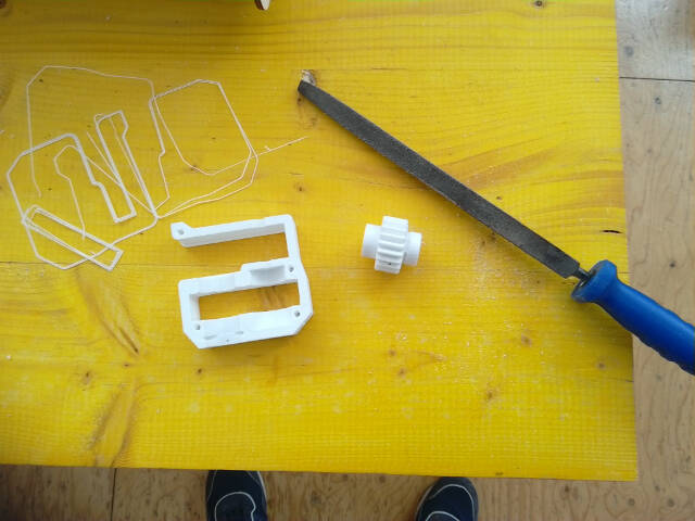
After the presentation I went back to the gearbox trying to understand the reason for such a jammed motion.
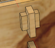
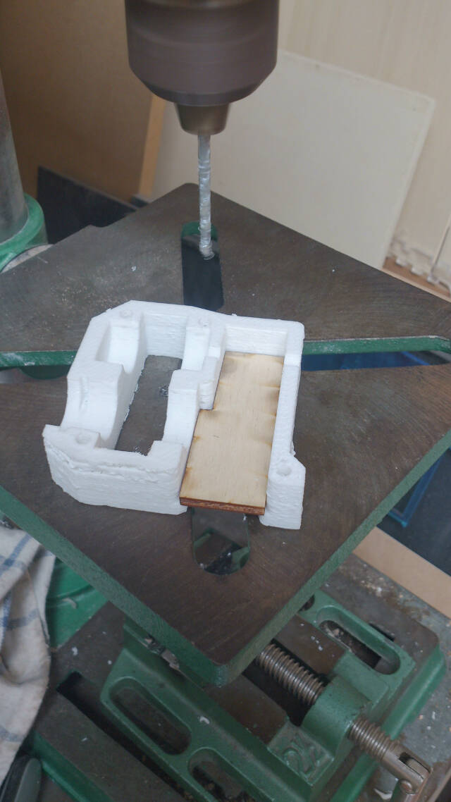
I could identify three main reasons, highlighted in the following image:
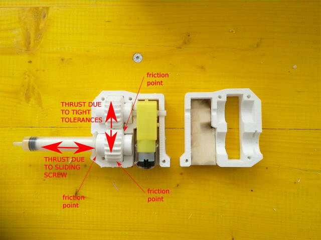
- The piston worm gear generates a thrust on the driving gear, pushing it against the walls of the body and thus creating friction;
- I underestimated the 3D printed tolerances (I am used to working with metals and do not yet master making precise assemblies with plastic…). Especially the gears nominal diameter was .2 mm bigger than expected on each gear and while they were rotating the tooths scrubbed against the casing;
- Also, the corners of the gears tended to get stuck in the corners of the casing. Some of the angles should be broken to avoid this.
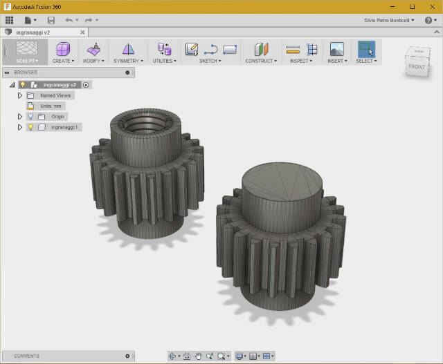
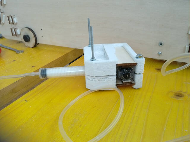
I therefore decided to redesign the gearbox taking into account these findings but, to avoid any possible problem, I also inserted in the assembly two ball bearings. They carry the axial thrust and help center the gears for a smooth rotation. here is the link to the Fusion360 file.
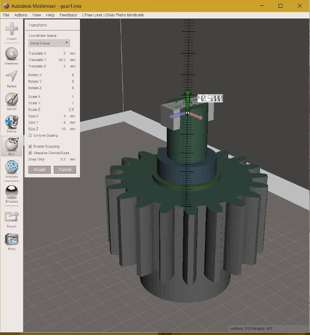
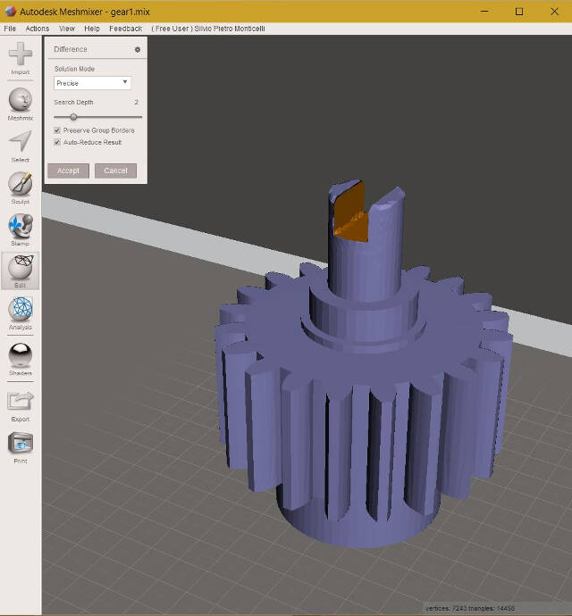
We had used an STL gear design which I could not modify in Fusion360. Since I did not want to spend time redesigning the gears I made the minor modifications using Meshmixer, a software
for working with triangle meshes (meshmixer.com)
The tool gives you also the ability to combine volumes and obtain the desired effects. For example, I created the slot on the shaft by subtracting the volume of a bom the shaft body.
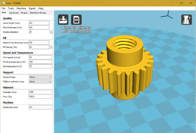
To gain better precision I 3D printed on the Delta Wasp 20x40 which is certainly a more sturdy and precise machine
I haven't yet completed the final gearbox.