Test the design rules for your printer(s)
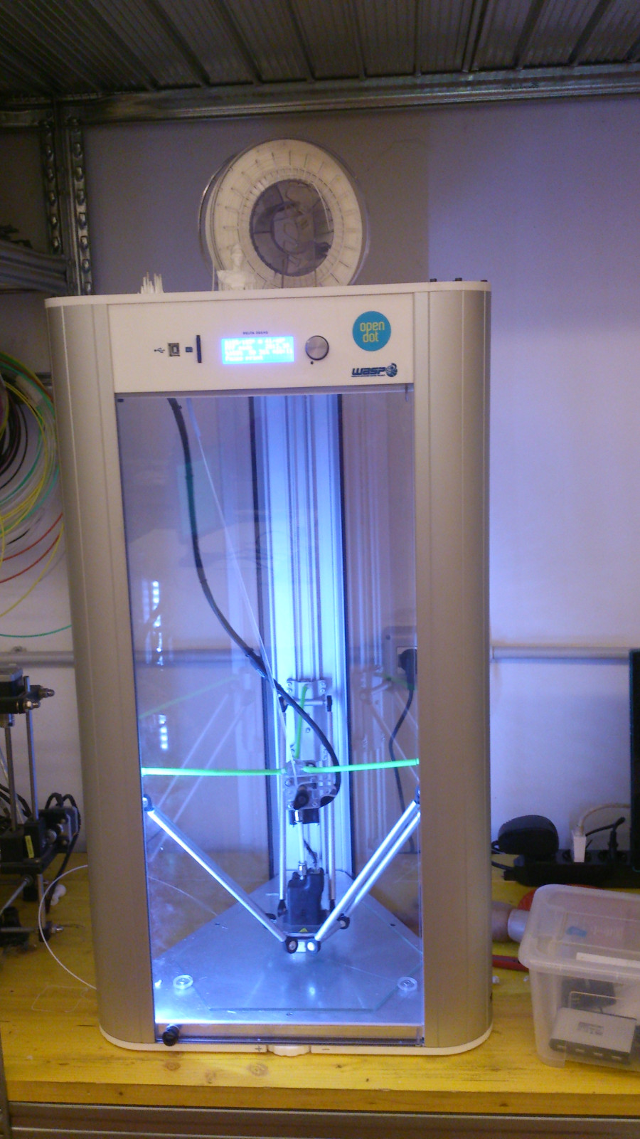
We had a first live tutorial with Tiziano Berti of Opendot on Thursday, March 3rd. We were introduced to the Prusa i3 by RepRap and, more specifically, to the Waspy Delta 20x40 that we will use.
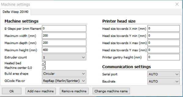
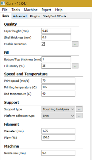
We had a detailed overview of the machine settings and of the print settings. Machine settings are really easy to address while print settings are tricky since they are greatly influenced by the type of object to print and cover a wide range of variables (basic, advanced, expert).
Basic settings are fundamental parameters which address object geometry: minimum wall thickness (0.8 mm), fill density (body sturdiness), general tolerance (< 0.1 mm), support type (overhang).
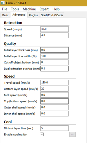
Advanced settings mainly address print speed (currently set at 4.2 mm/s) and speed variance in different part of the body. In this case speed lowers to 20% of the nominal value when printing the initial bottom layer to improve adherence to base plate.
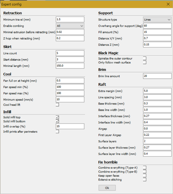
Expert configuration addresses the starting point of the print with skirt, brim and raft (check here for a clear explanation). Crucial is the support overhang angle which is set, by default, at 60° (30° from horizontal plane). This is a strong constraint on printable geometry.
Design and 3D print an object
I linked this assignment to my semester project. There are, in fact, different items that could possibly be 3D printed. The most interesting one is the multidirectional wheel. Moreover, printing the whole wheel, core and free rollers, in a single operation, certainly could not be done with a subtractive machining method and would really highlight the potential of the 3D printing process.
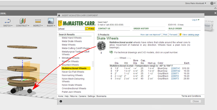
In the second week assignment (computer-aided design) I made the design of my project in Fusion 360. This package lets you choose standard components from different sources, one being McMaster-Carr. catalogue. Here I had found a type of multidirectional wheel which I added to my design (McMaster wheel link).
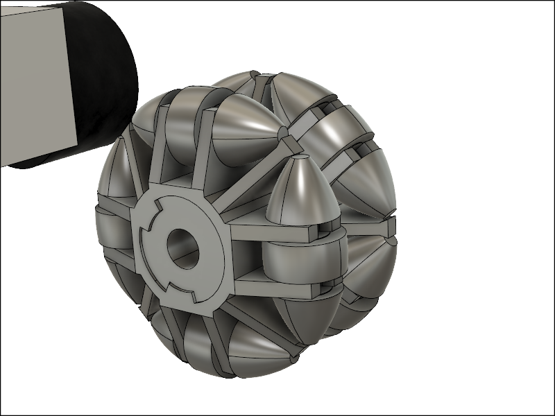
Instead of harnessing with the McMaster object I decided to redraw the whole wheel. Here's the link to the Autodesk A360 page (e-mail needed for download): Multidirectional wheel 3D print.
The file can also be downloaded at this link (no e-mail needed): Multidirectional wheel 3D print .step
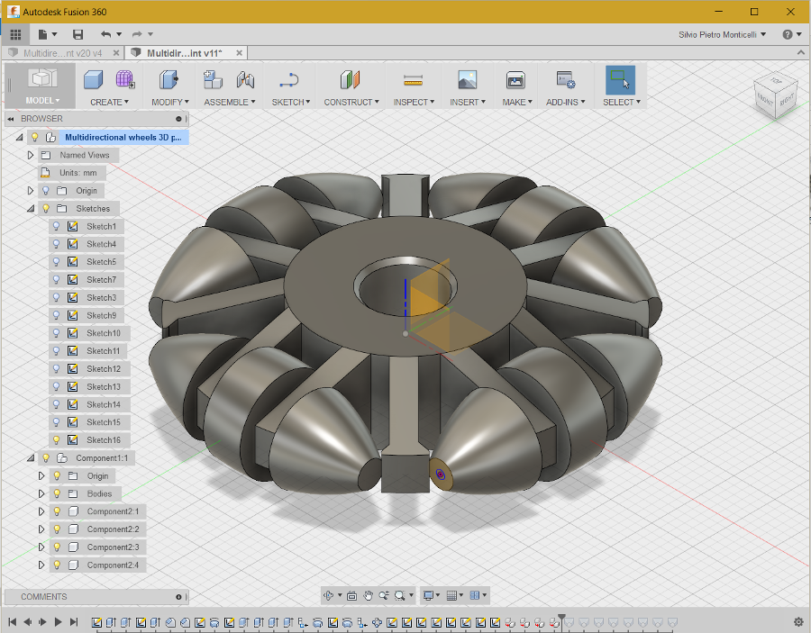
In this case sketches are very useful since they provide construction lines that reference different geometries (axes, dimensions, relative position of rollers and core). Here is the animated design history played with the design history functionality of Fusion360
(Design history video).
A key issue in 3D printing to get the rollers free to rotate is the play between parts. I do not have specific experience on 3D printing backlash but since the Wasp machine in Opendot has a resolution of circa 0.1 mmm, I set the play at 0.6 mm on the roller axle and 0.6 mm on the roller walls (0.3 mm on each side).
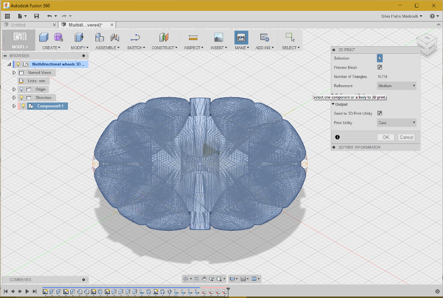
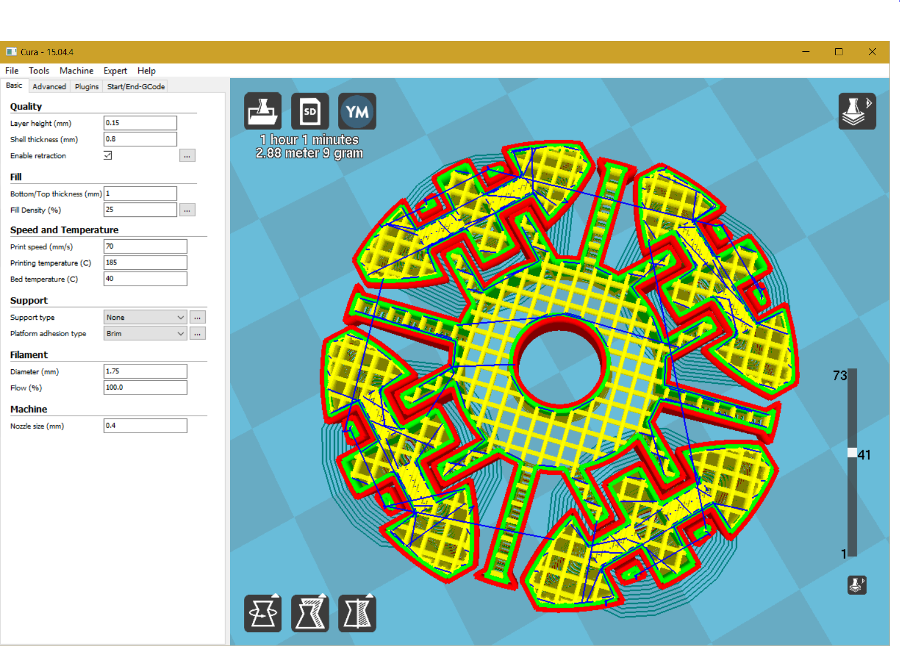
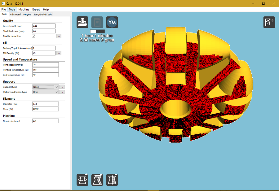
Now, I made the object printable with the “Make/3D Print” instruction. The selected Print Utility is Cura. When I select the object, the print utility shows the mesh structure and clicking ok opens the file in Cura.
Here we can make different analysis of the body structure.
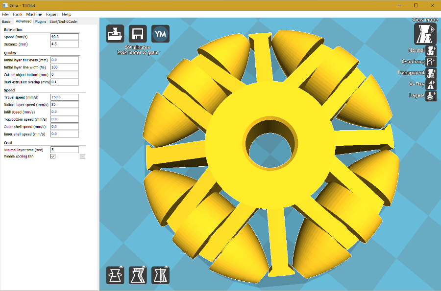
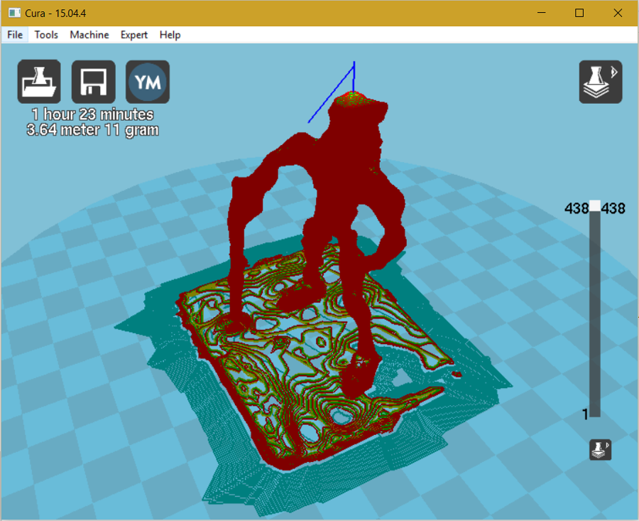
I first checked the layers structure. Starting from the initial layer up to the middle one. We can easily see that a problem will arise when the roller axle will start being printed. In fact, the first horizontal axle layers will not be supported and will drop on the brackets structure. Hopefully, this line of contact may be easily broken rotating and sliding the roller ....
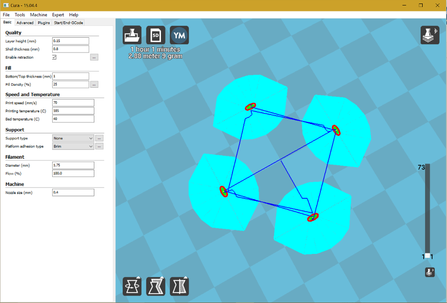
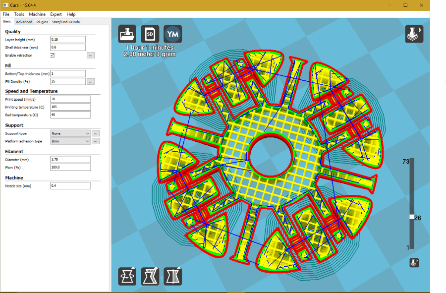
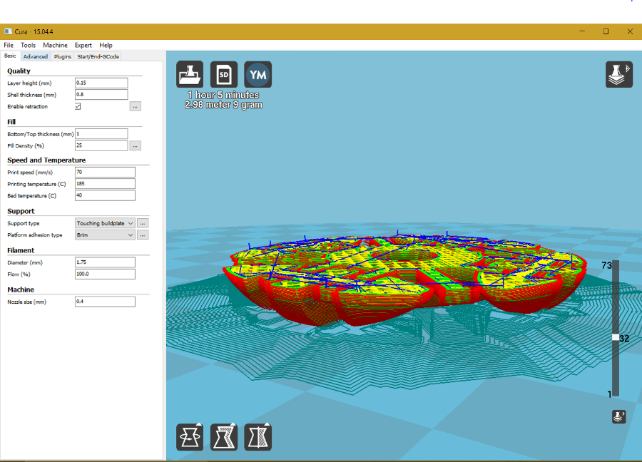
I then checked for Overhang. I set the support to “Touching buildplate”. In this case the support structure will not be everywhere but only where it touches the base plate. Surprisingly, it only increases print time by 4 minutes.
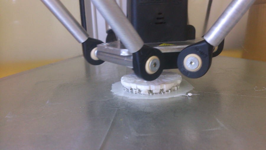
I had made a first print without including platform adhesion and the print did not stick to the baseplate. I then selected Brim adhesion type which places a single layer thick flat area around, and not under, the object.
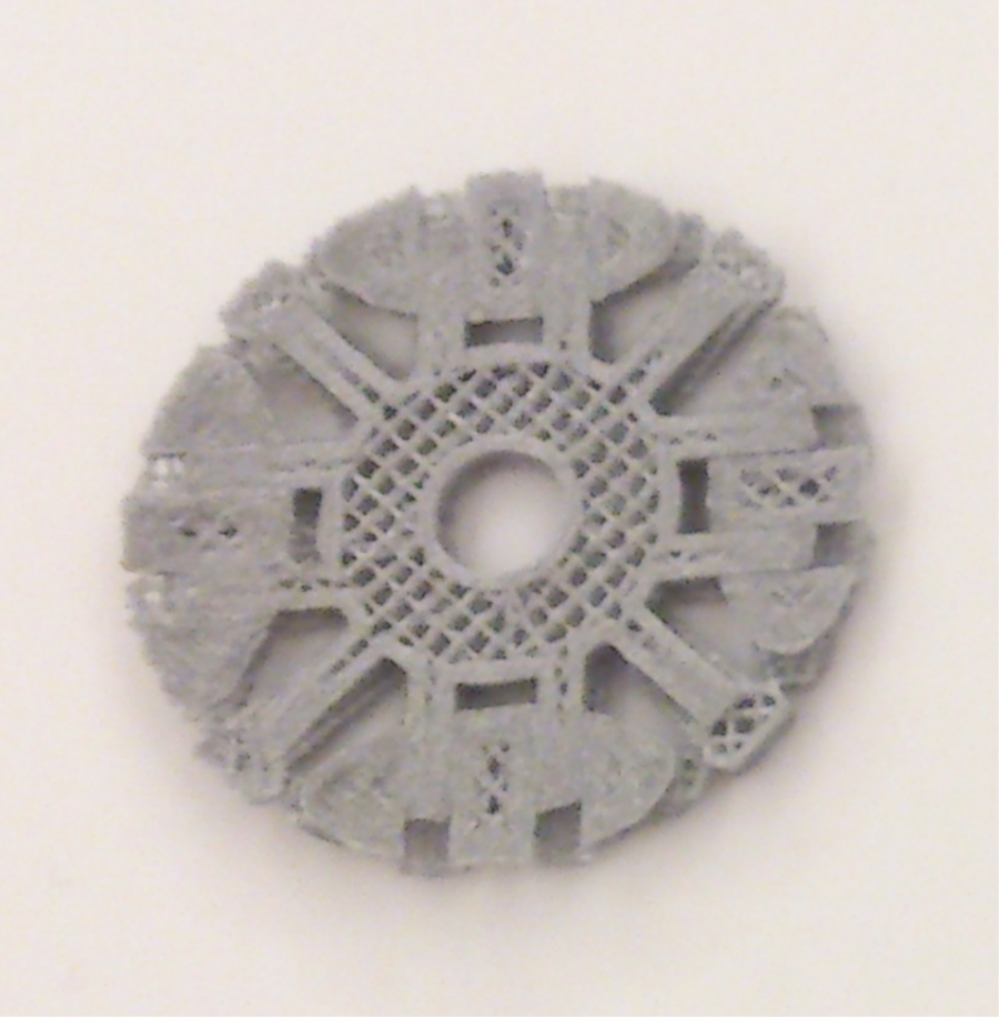
Second try.
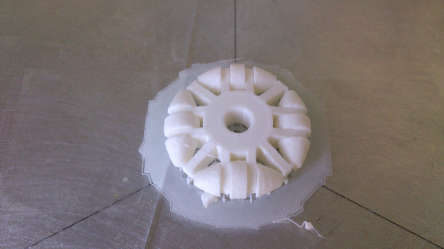
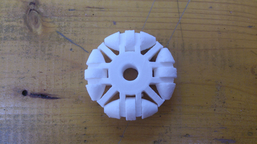
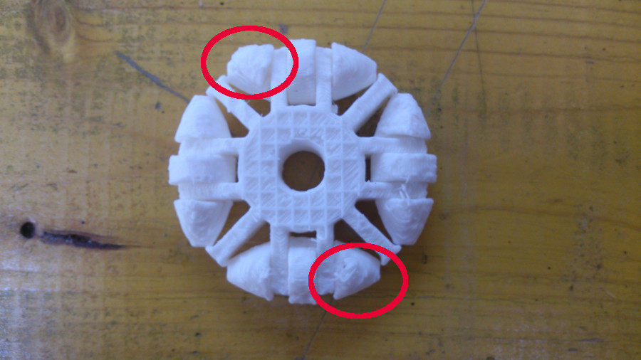
The result looks nice from the front face. But if we look at the back, we can clearly see the supports were not sufficient to hold the end of the rollers in place. Moreover, the rollers are not turning. I expected this since printing the wheel laid down could not create a support to the first layers of the rollers' axle. In the next days I will try a different solution.
3D scan and print an object
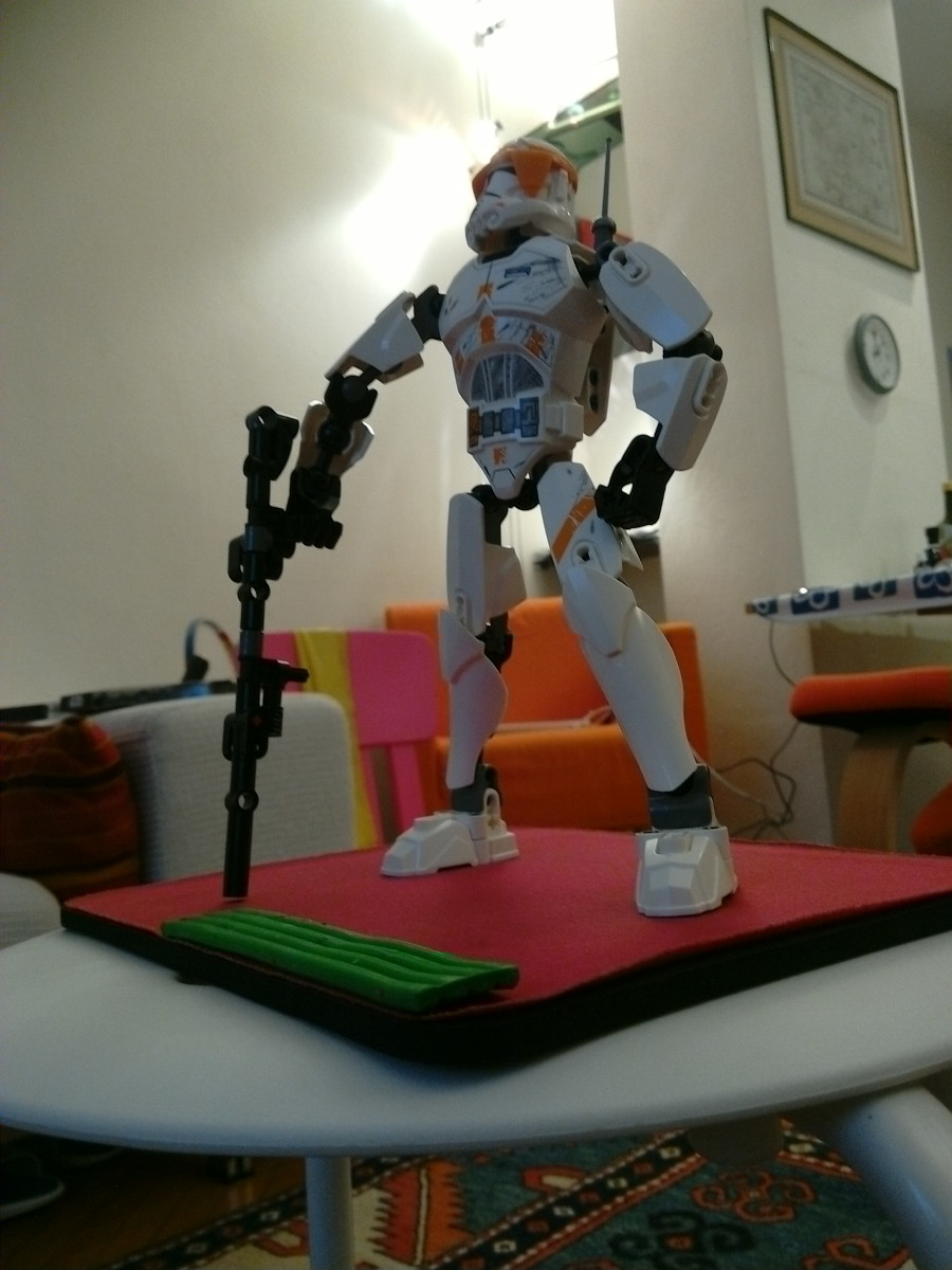
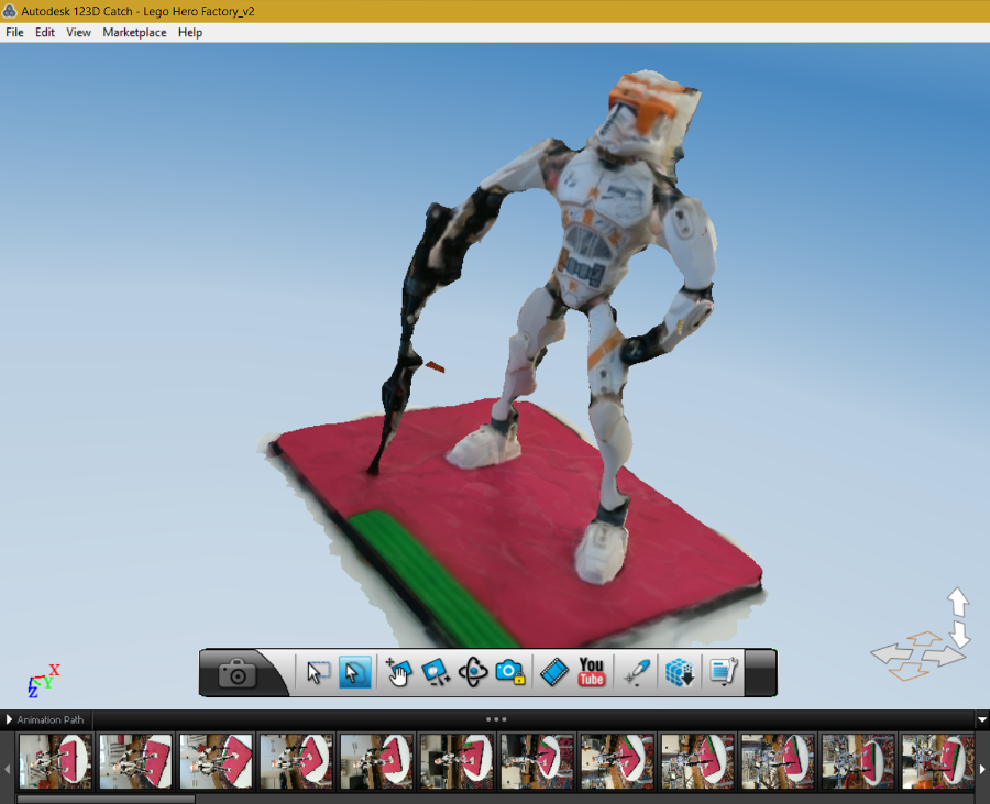
I made this exercise with one of my son Lego figures, the Star Wars clone commander Cody. It looks sufficiently intricate to put to test the scanning capabilities of 123D Catch and Meshmixer.
I took several 123D Catch tutorials on the official website to understand the best way to capture the images necessary to create the 3d model. I came up with 63 photos divided over three planes, middle, high and low (in the tutorials they suggest between 50 and 70 photos with a maximum size of 3 Mp). Certainly, correct lighting conditions are fundamental to obtain a good rendering of the object. You need to avoid over or under exposure. But in a normal room, where light has different intensity in different directions, it is difficult to achieve optimum conditions.
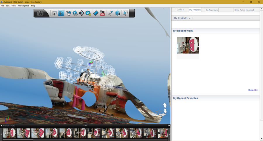
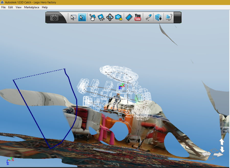
The result included images of the surrounding which I deleted using the Lasso selection.
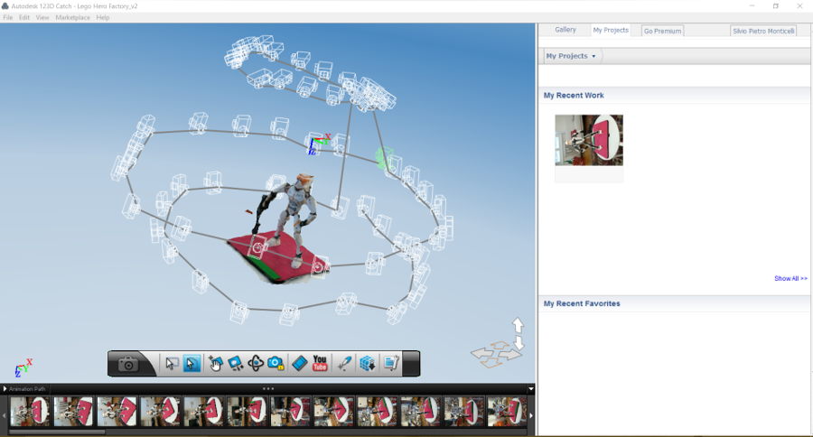
To be honest, I expected to get a better result. The object looks as if it was wrapped in some kind of transparent material. The antenna to the right of the helmet is completely fused with it.
And the blaster really looks disappointing. I agree I should give it a better try and maybe choose a subject more consistent with my experience and my available means. Or maybe, try another software.
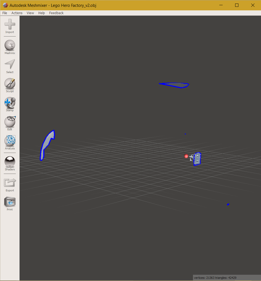
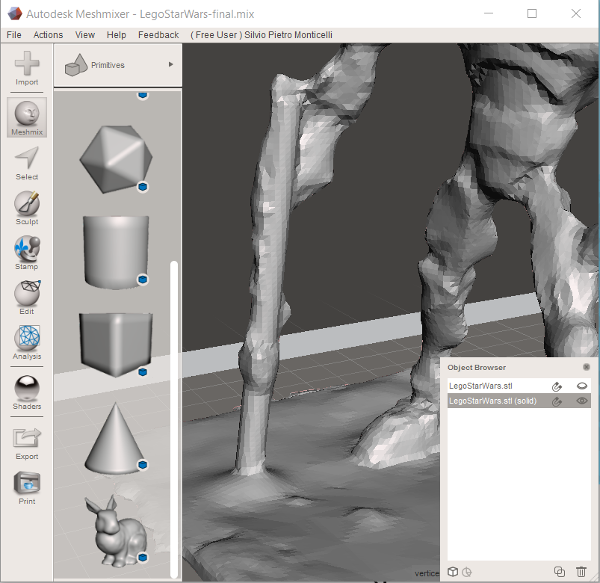
Nevertheless, to keep the schedule, I uploaded the file in Meshmixer and checked the available tools to improve the model.
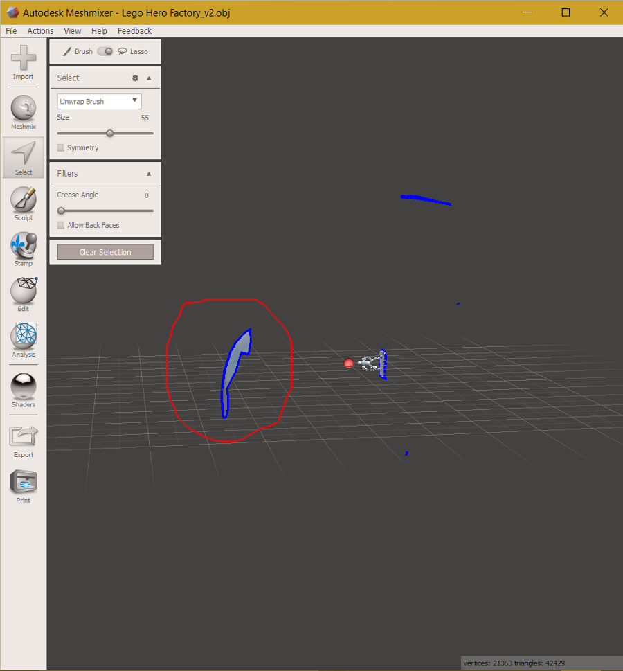
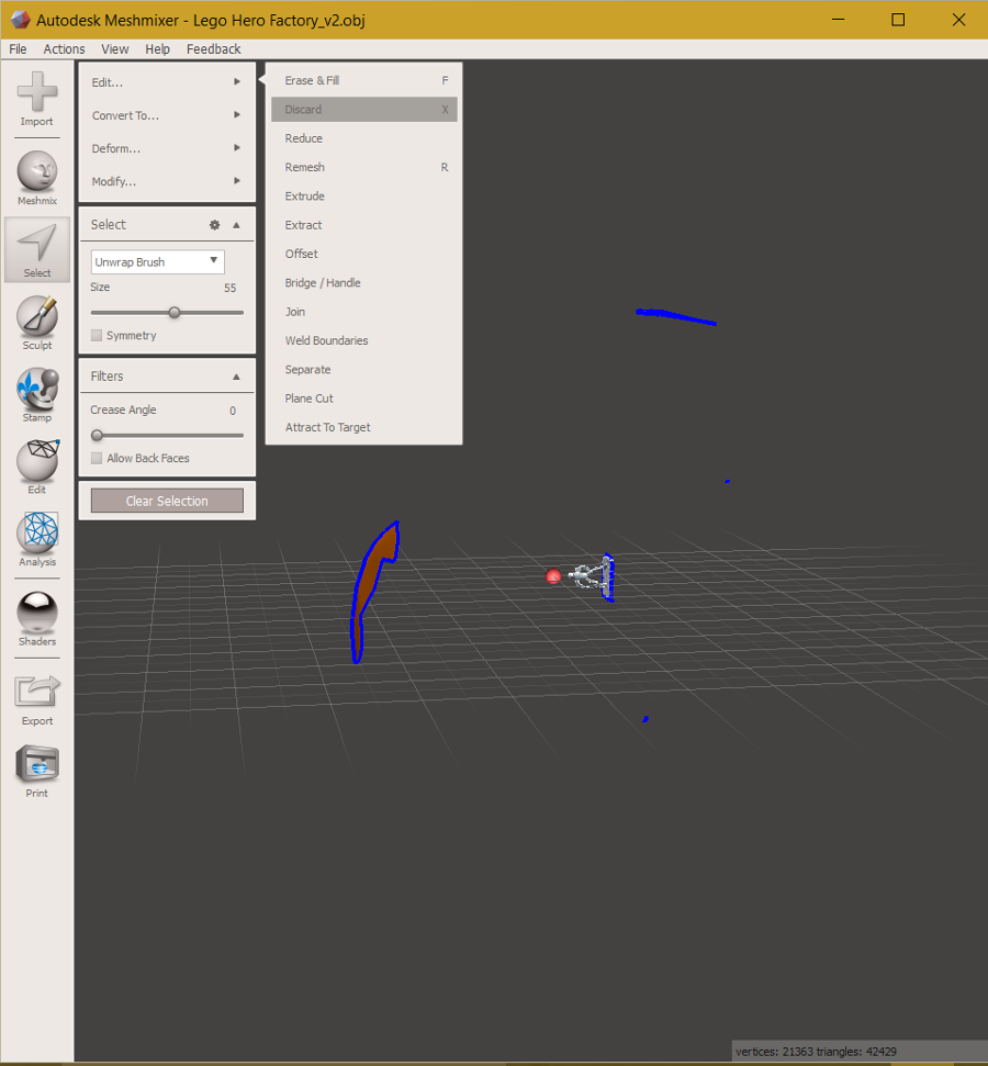
The file still needs some cleansing and the object must be rotated. I used the lasso function for cleansing. Once highlighted you can discard the selected area.
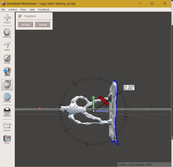
I used the Transform function, which brings in manipulators, to rotate the body of exactly 90°.
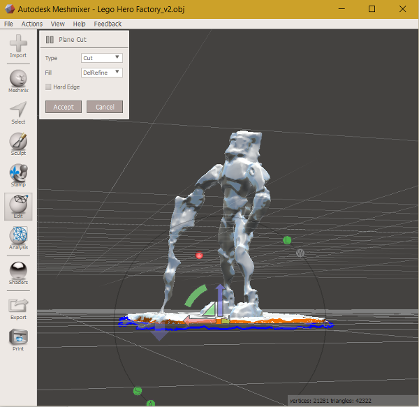
In view of 3D printing I needed to make the bottom of the object flat. I used the Planecut function which lets you adjust the position of a cutting plane in space.
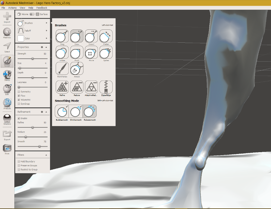
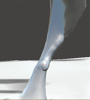
And now comes the funniest task. Adjusting the mesh! I tried the sculpt tool with a wide range of brushes and settings. This way of improving the object body and surface is really powerful, though time consuming. I hurried up to put some material at the tip of the blaster, where it meets the base plane, and on the left calf.
Since sculpting needs some practice I changed approach for the blaster. I added to the scene another body, a cyclinder, from the meshmix menu which I then resized and merged with the body of the commander. In the meantime, I updated Meshmixer version to 3.0.
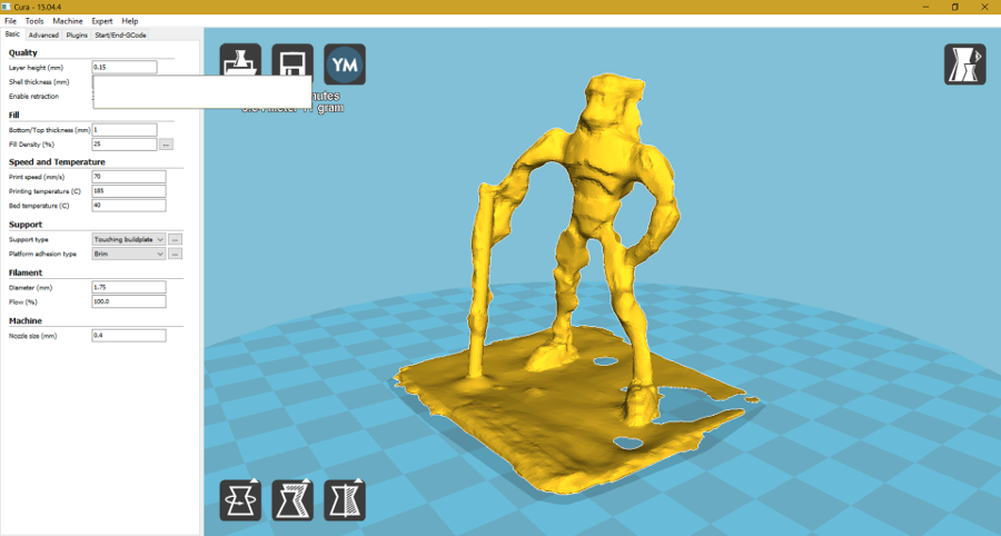
Here the final result that I will export as an .stl file and import in Cura (link to Meshmixer design).
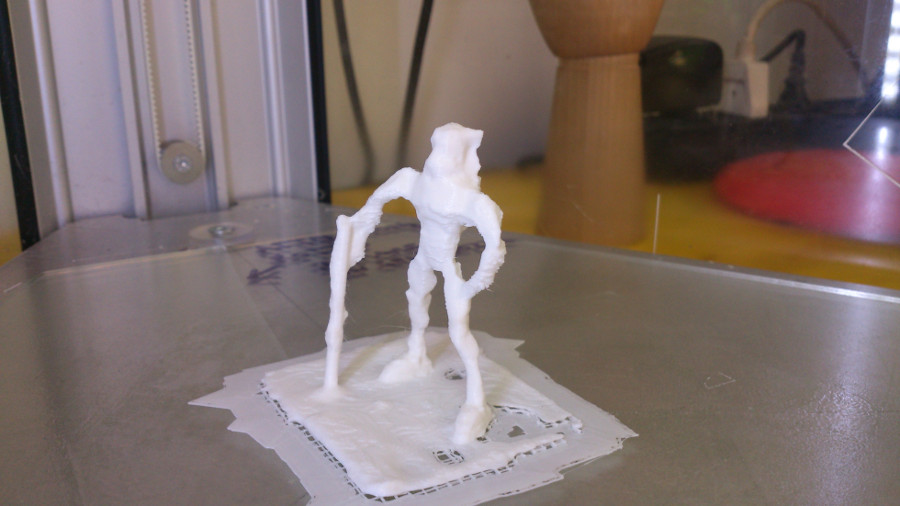
This the file in Cura, ready for printing.
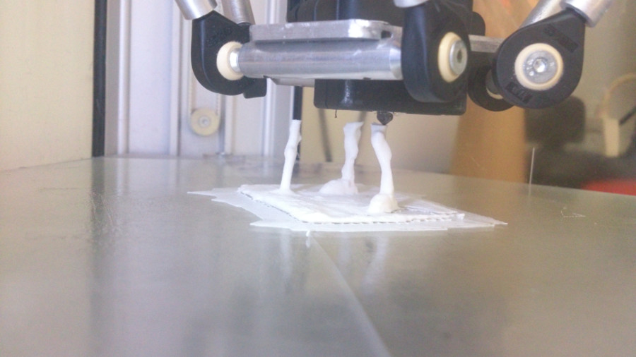
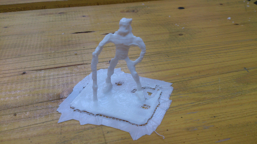
Let's print.
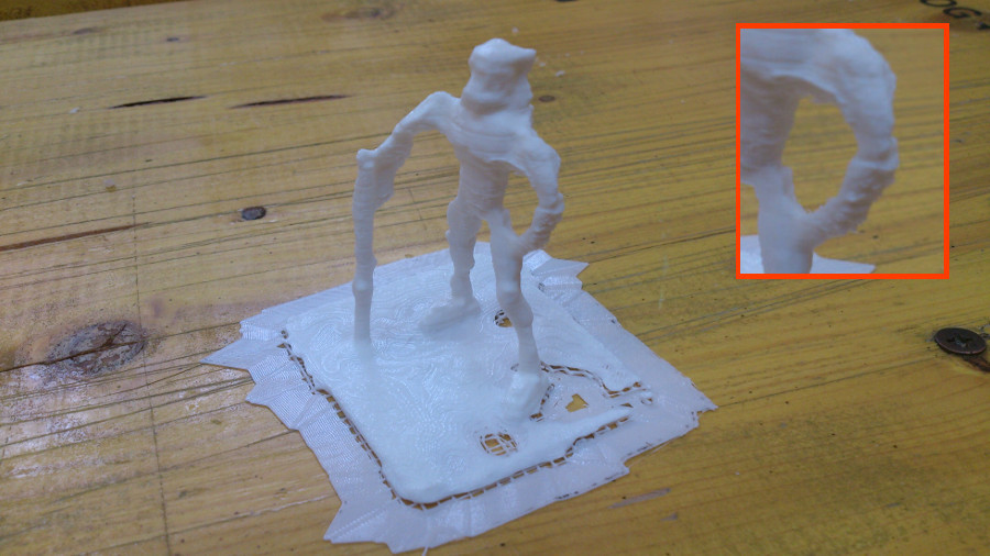
While the printing head was depositing material on the left arm it created a traction force which bent it. Material is therefore layered in a non-uniform way. Object size, printing speed and support strategy should be better optimized.