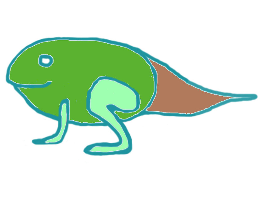
I wanted to make something for my son. He loves nature and he enjoys holding animals in his hands. For example frogs. So, I thougt that the frog lifecycle - egg (spheroid), tadpole (spheroid with tail), adult (spheroid with arms and legs) - could be a very nice project to develop. Starting from a simple geometry you can add or remove additional parts and play with the frog evolving bodies.
Here is the GIMPI sketch of the different sections
Joinery and shapes
The day after Neil lecture Enrico, our instructor, gave us a tutorial on laser cutting with a specific focus on joinery.
Clearly, joinery is the main issue. So, I tried to figured out the best joints for this assignement. The joints should make it easy to assemble the different parts of the body: body slices, arms, legs and tail.
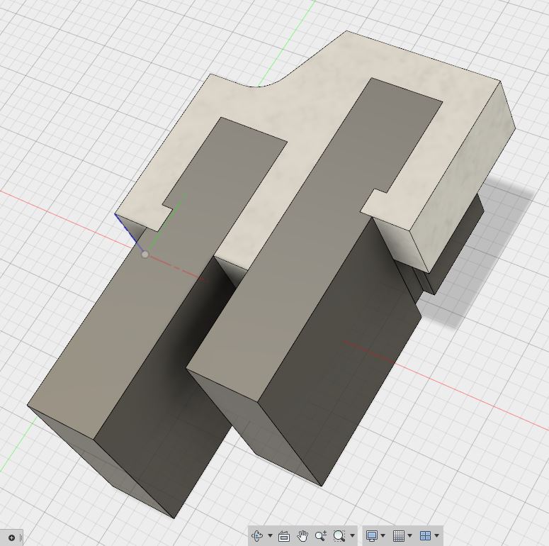
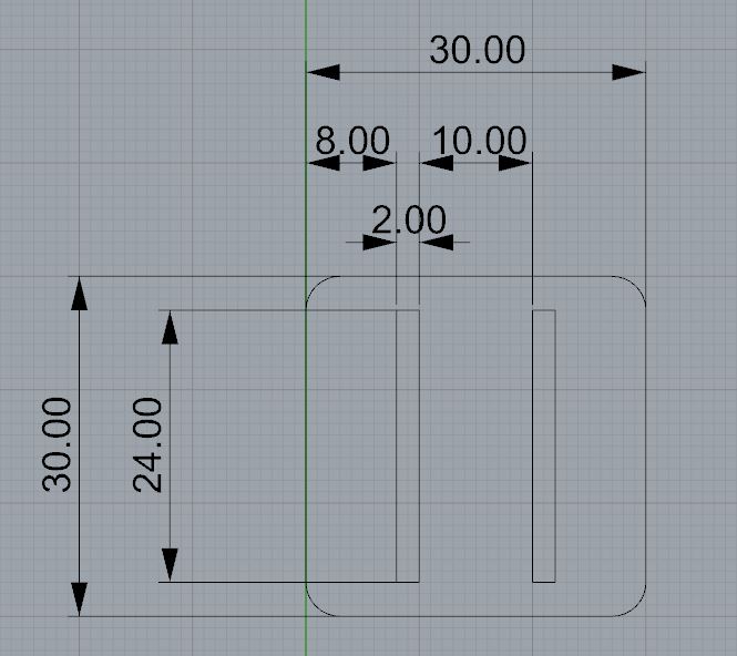
Here is the snap-lock joint that should hold together two carboard elements. The hooks engage in slots that prevent the clip from sliding out. I made the drawing in Fusion 360 for the greater flexibility you get when you draw from scratch.
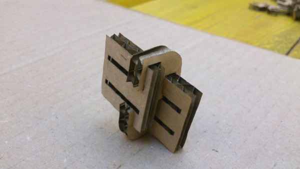
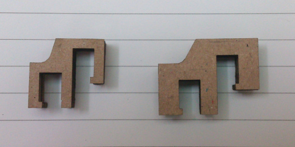
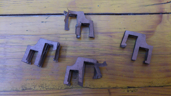
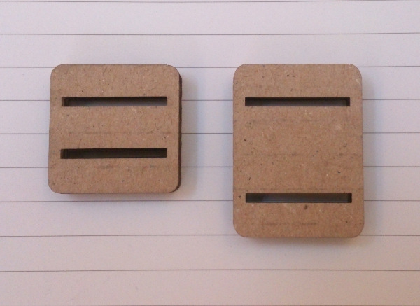
I tried out different clip sizes. I wanted the clip suffciently compact but also resistent. Here you can see the thin initial size and the final, more thicker, one. The first shape wore off quite quickly after a couple of insert/extract cycles (right picture). Moreover, the legs got easily distorted. The final shape can be used four/five times.
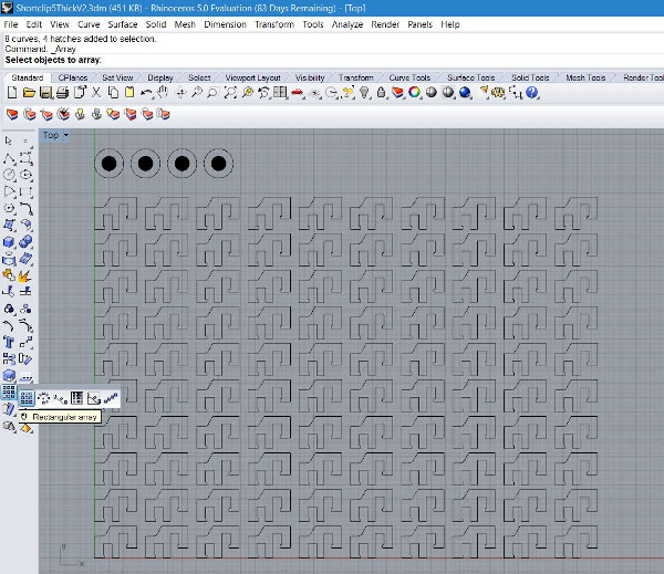
Here's a set of joints ready for printing with Rhinoceros. I created the printing array starting from a single joint and using the "rectangular array" command. The circles at the top are the "eyes" of the frog (link to design)
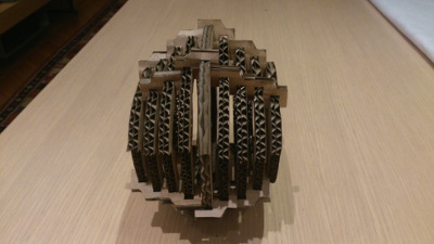
The second step are arms and legs. I did not want to use a single cut shape but a set of tiles taht could also be used to make the tail and the body.
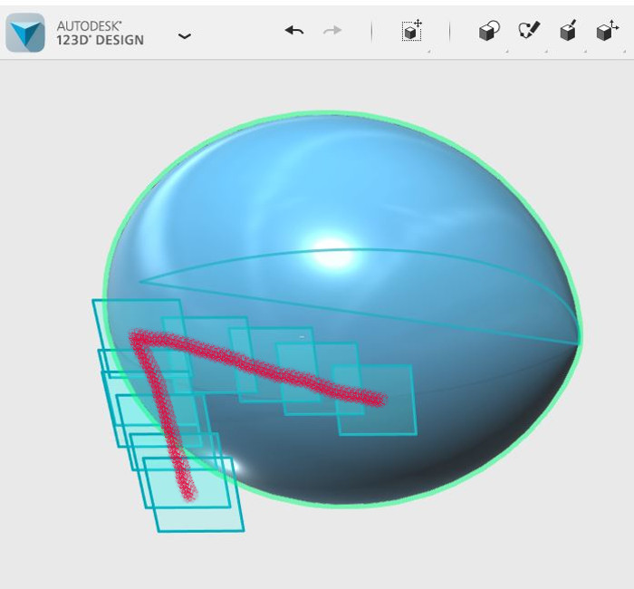
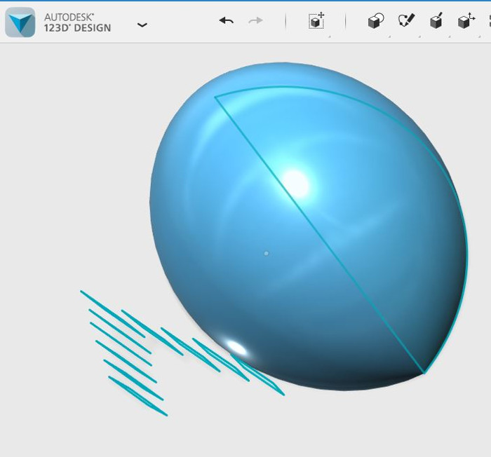
The tile should be asembled in an upward and downward direction, while diverging from the body/egg. Here is what I figured out using 123D. The pictures show a concept for the left leg.
These are the shapes of the selected tiles, each with different lengths (30 and 40 mm) but the same width (30 mm) and pitch (7 mm) (drawing with Rhinoceros 5.0
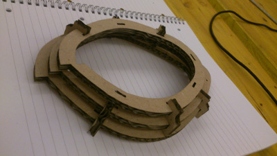
Finally the body. Putting together a set of tales aronund a spheroidal body got more complex than expected. So, I opted for a series of "slices", cut ollow to keep them light. The tail was also made of a single piece.
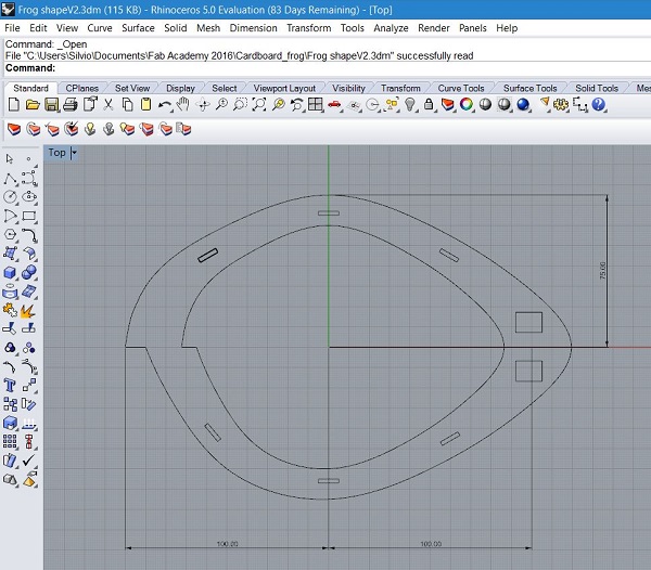
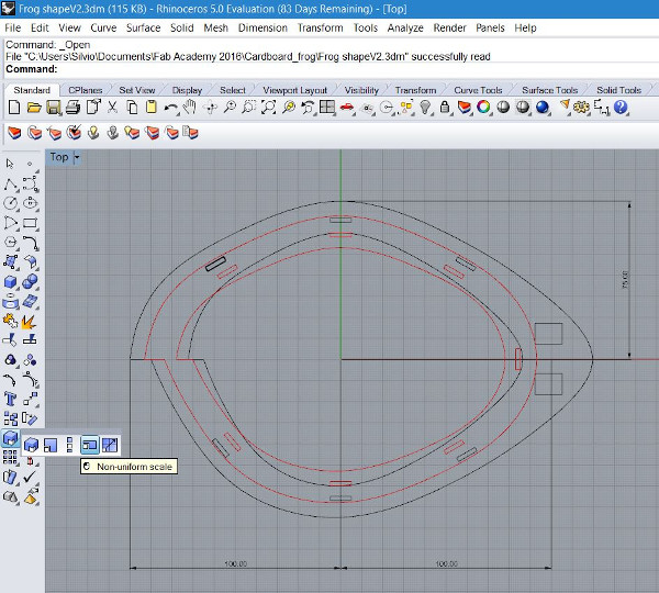
The slices were easily drawn, starting from the most external (left picture), using a very practical feature of Rhinoceros, the Scale 2-D/Non-uniform scale command. See the red lines in the right picture (link to design).
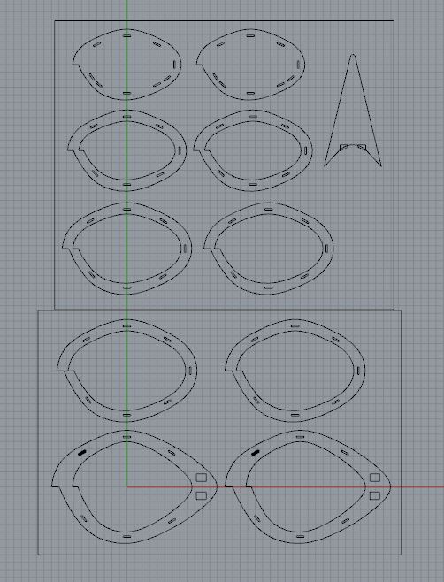
Here is the full set of slices with the tail, ready for printing (link to design).
The final assembly
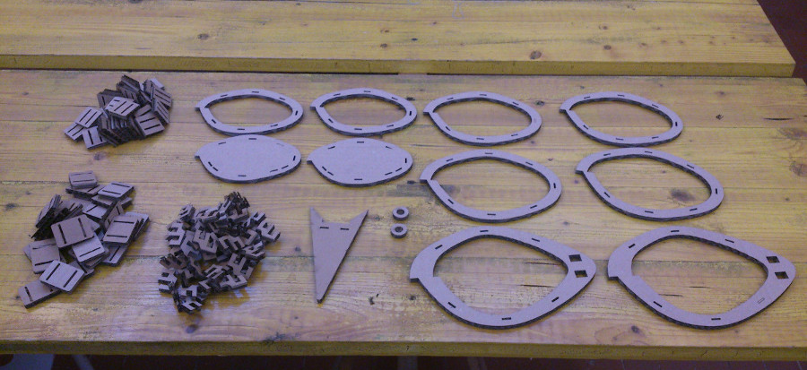
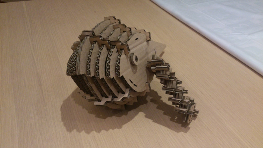
We are now ready to assemble the frog. I laid out on a table all the different elements:body slices, tail, joints, tiles, eyes.
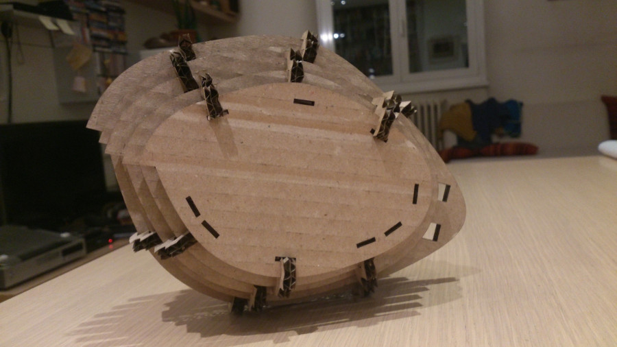
Let's start with the body to obtain the initial stage, the egg.
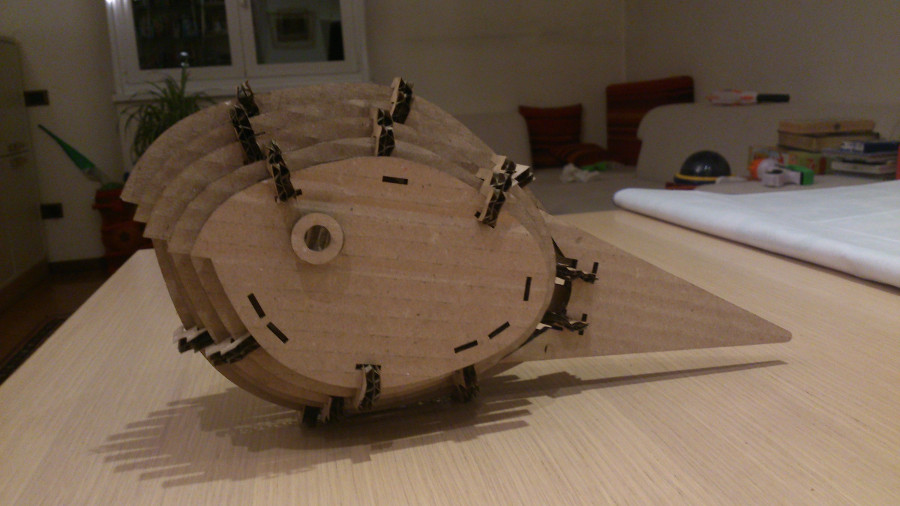
Let's add eyes and tail and here it is, the tadpole.
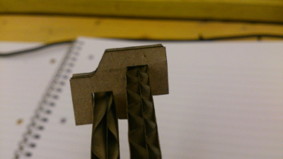
Last things legs and arms. Unfortunatly, the tile pitch was too short. I needed too many tiles to assemble the full leg. The final strucutre, by diverging too much from the body, became too weak. Here is the result. I didn't like it.
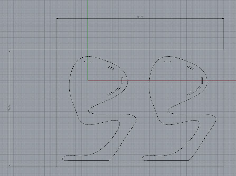
So, to cut a long story short, I planned to make the legs in a single piece. This the final drawing in Rinoceros. The legs are superposed with the first body slice (link to design).
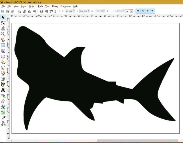
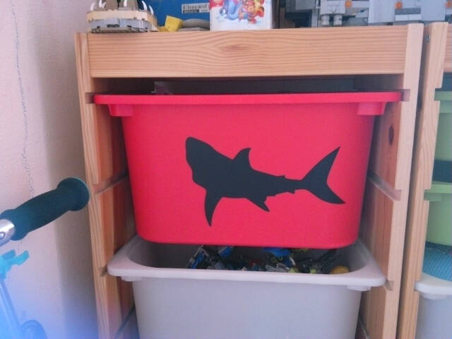
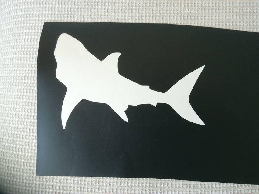
I asked my son for an image he would like to stick on the cover of one of his notebooks. A shark, he shouted enthusiastically. I went looking for a nice image in a website where all the images are published under Public Domain (Creative Commons C00) that is, they can be used for any purposes without restriction: Pixabay.com.
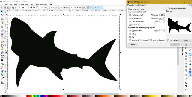
I found the following image which I downloaded and opened in Inkscape.
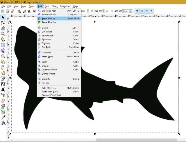
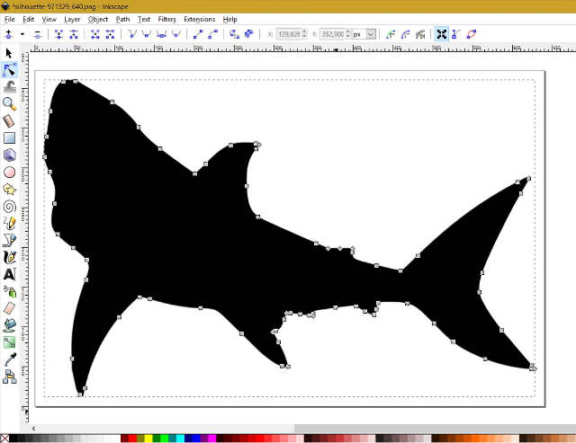
I then used the Path - Trace Bitmap tool to transform it into a vector image.
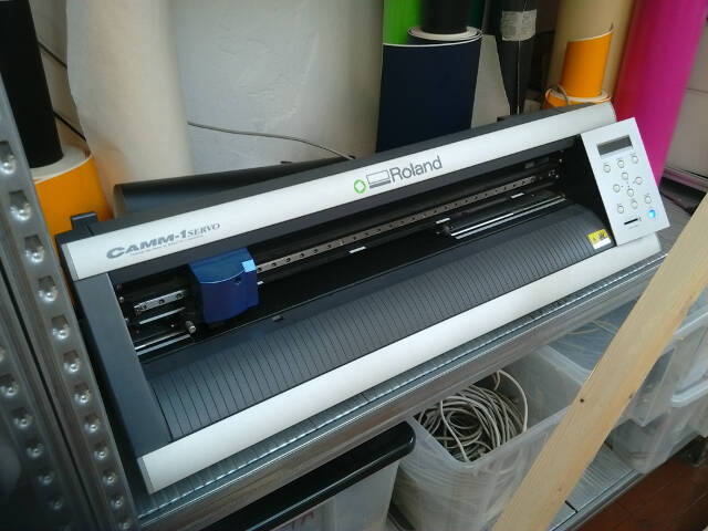
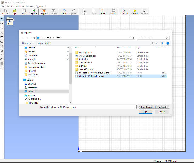
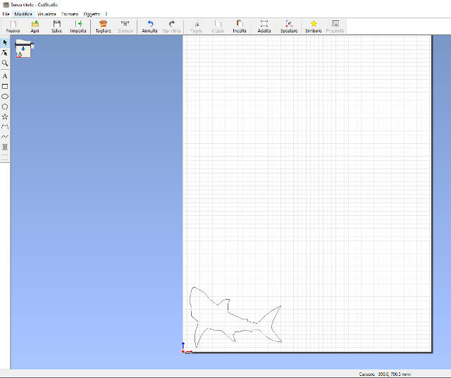
In order to cut the sticker with the GX24 Roland vinyl cutter, I needed to copy the Inkscape file to the desktop of the PC connected to the machine and open it with the dedicated software CutStudio.
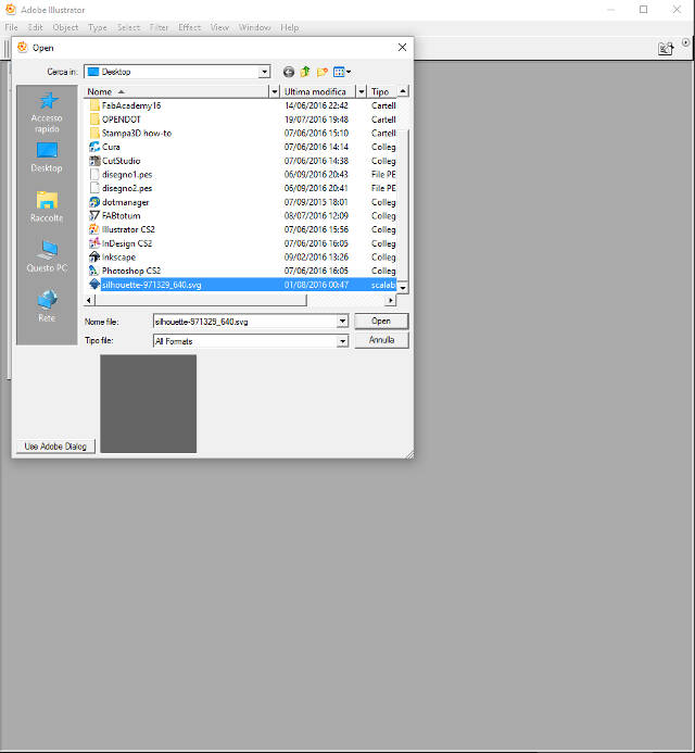
To do this I was instructed to first upload the file in Adobe Illustrator (there seems to be a compatibility issue between the available versions of CutStudio and Inkscape).
Here is the step by step sequence:
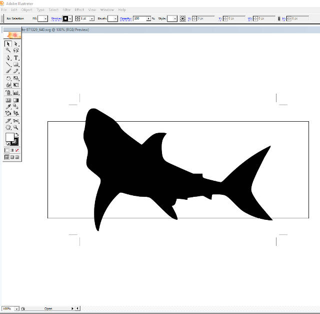
Open the file in Illustrator;
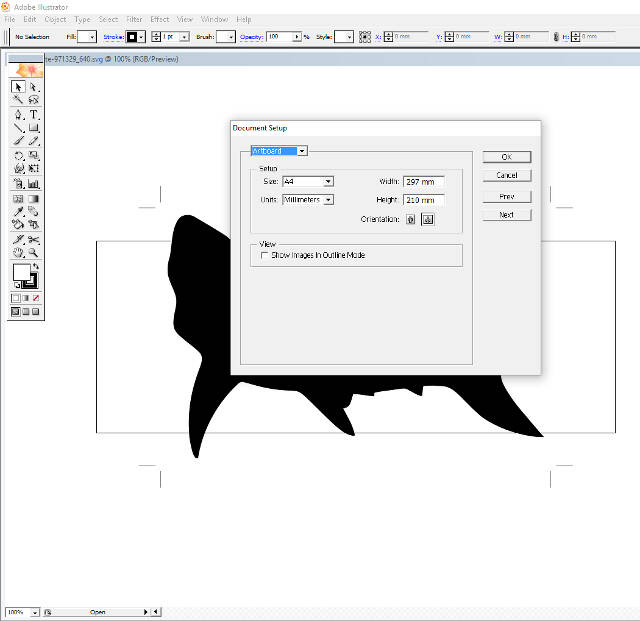
Set the document to size A4;
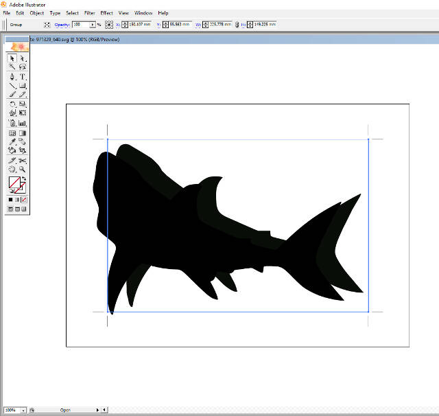
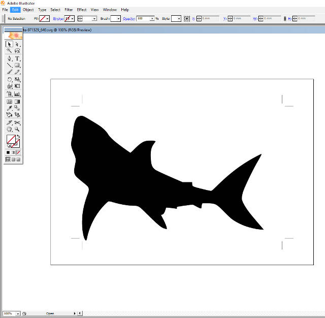
Remove the duplicated background image;
Save the file to the desktop with the extension .ai (Adobe Illustrator file);
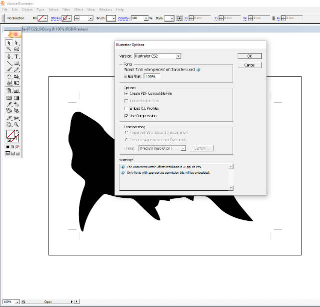
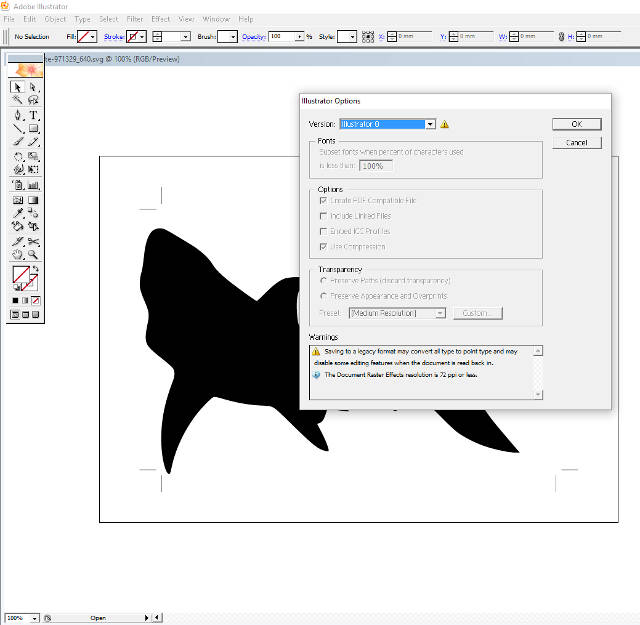
Since I was not sure which version of Illustrator is compatible with CutStudio I downloaded two copies of the file using the "Illustrator Options" window: one copy set to the last Illustrator release available (CS2) and one to a previous version (v8);
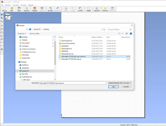
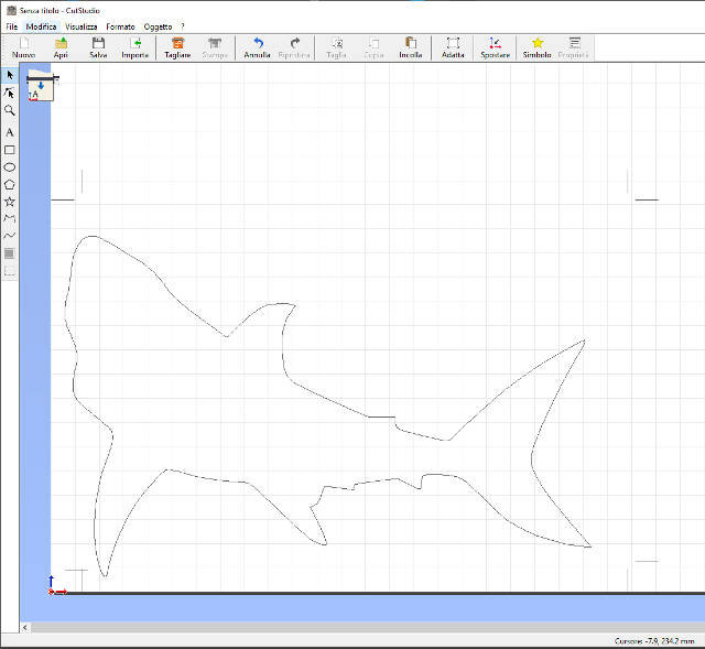
Next step, I switched on the machine, which performed an automatic alignment cycle of the cutting head, and opened the .ai file with CutStudio.
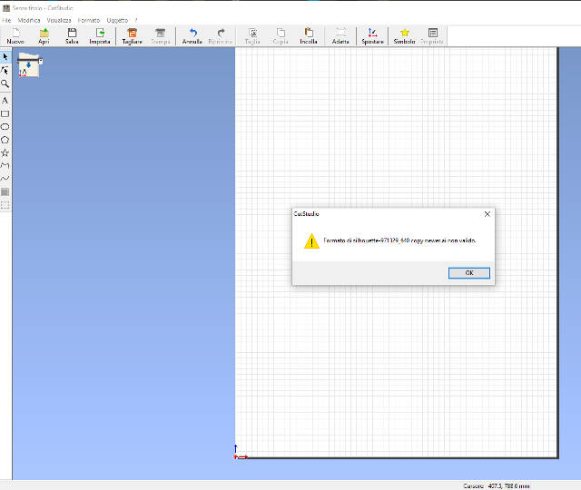
Indeed, the file in the newer version of Illustrator could not open.
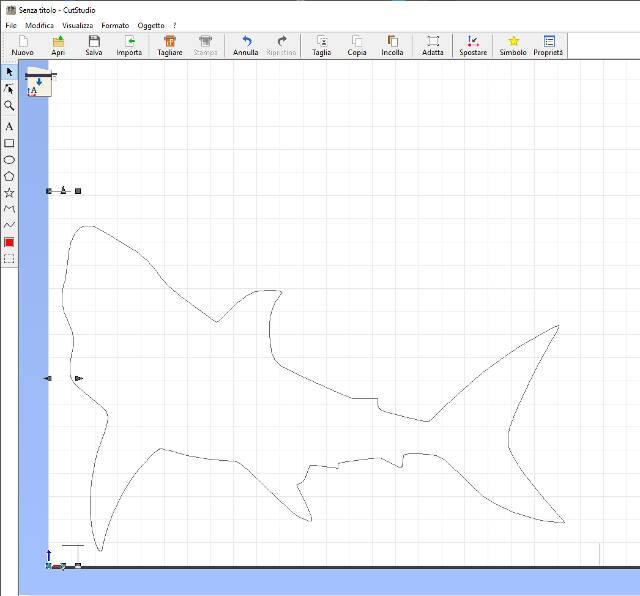
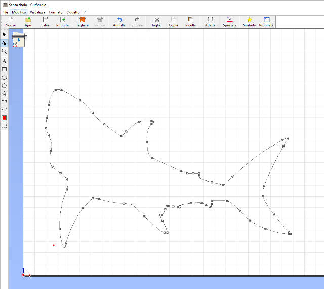
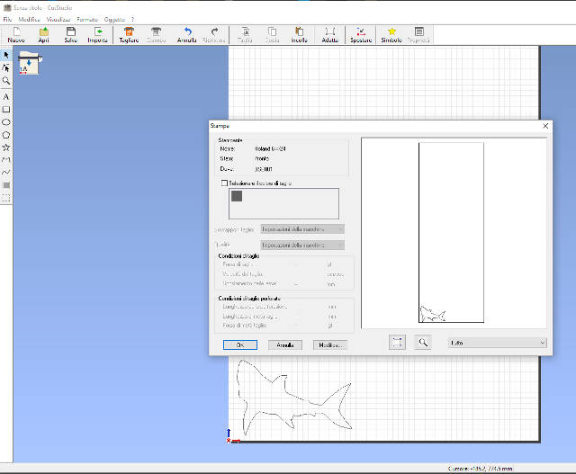
I cleaned the file from the center lines that were left over in the transition from the two softwares and checked the position of the image in the print environment. I then opened the "Print" window and clicked ok
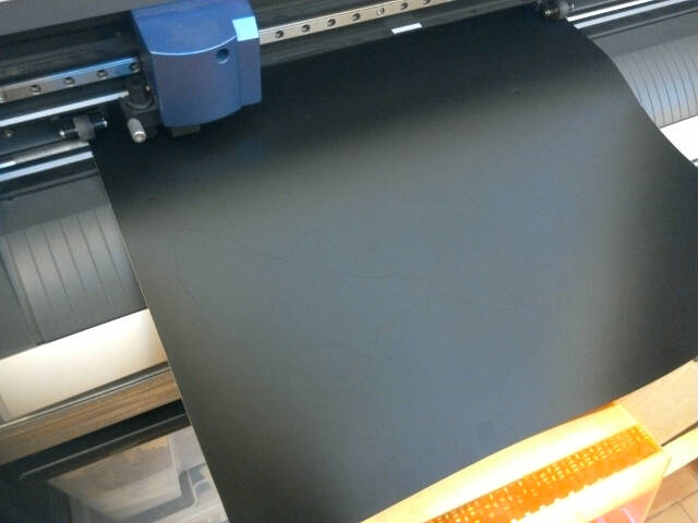
In the following picture we can see the final sticker and the cut line of the cutting head.