Add an output device to a microcontroller board
PCB design
For some weeks I have been designing control board for my final project. The control board has three outputs: motors (1), speaker (2) and leds (3).
You can download Control Board Cut File here and Traces File here.
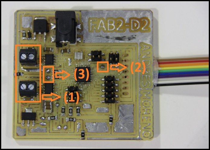
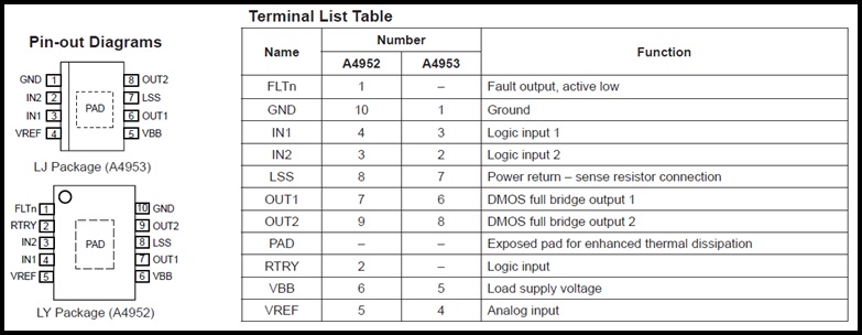
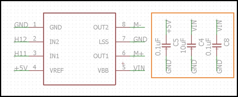
For control the speed and direction of motors I used A4953 driver. Each input of driver is connected to PWM output pin of microcontroller.
Is important to use a capaciter filter for each driver ortherwise the microcontroller is reseted when the motors turn on.
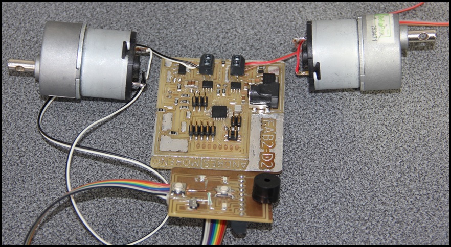
For speaker and leds I designed other board. You can download Cut File here and Traces File here.
Connect the motors and spaker and leds board.
Programming Microcontroller
Motors are controlled by PWM outputs and driver.
void setMotors(signed int v1, signed int v2){
  // verify PWM limits (-255 to 255)
  if(v1 >  255) v1 =  255;
  if(v1 < -255) v1 = -255;
  if(v2 >  255) v2 =  255;
  if(v2 < -255) v2 = -255;

  // set motor1 speed
  if(v1 > 0){
    digitalWrite(H11, LOW);
    analogWrite(H12,   v1);
  }
  else{
    analogWrite(H11,  -v1);
    digitalWrite(H12, LOW);
  }

  // set motor2 speed
  if(v2 > 0){
    digitalWrite(H21, LOW);
    analogWrite(H22,   v2);
  }
  else{
    analogWrite(H21,  -v2);
    digitalWrite(H22, LOW);
  }
}

void offMotors(){
  // set all pwm high to fast break
  digitalWrite(H11, HIGH);
  digitalWrite(H12, HIGH);
  digitalWrite(H21, HIGH);
  digitalWrite(H22, HIGH);
}
The complete code consist in recibe a code from serial port and move the motors. This are the codes available and it function:
- f : move forward.
- b : move backward.
- l : turn left.
- r : turn right.
- s : stop.
#define H11 5
#define H12 6
#define H21 9
#define H22 10

#define SPK 2

#define LD1 7
#define LD2 8

#define BTN 11

long t0;
char dir = 'S';
boolean togPin=0, toggle=0;

void setup() {
  Serial.begin(115200);

  pinMode(H11, OUTPUT);
  pinMode(H12, OUTPUT);
  pinMode(H21, OUTPUT);
  pinMode(H22, OUTPUT);

  pinMode(SPK, OUTPUT);

  pinMode(LD1, OUTPUT);
  pinMode(LD2, OUTPUT);
}

void loop() {
  if(Serial.available()){
    dir = Serial.read();
    switch (dir){
      case 's':
        offMotors();
        toggle = 0;
        break;
      case 'f':
        setMotors(127, 127);
        toggle = 0;
        break;
      case 'b':
        setMotors(-127, -127);
        toggle = 1;
        t0 = 0;
        break;
      case 'l':
        setMotors(0, 127);
        toggle = 1;
        t0 = 0;
        break;
      case 'r':
        setMotors(127, 0);
        toggle = 1;
        t0 = 0;
        break;
      default:
        offMotors();
        toggle = 0;
    }
  }

  if(toggle){
    switch (dir){
      case 'b':
        digitalWrite(LD1, togPin);
        digitalWrite(LD2, togPin);
        digitalWrite(SPK, togPin);
        break;
      case 'l':
        digitalWrite(LD1, LOW);
        digitalWrite(LD2, togPin);
        digitalWrite(SPK, LOW);
        break;
      case 'r':
        digitalWrite(LD1, togPin);
        digitalWrite(LD2, LOW);
        digitalWrite(SPK, LOW);
        break;
    }
    if(millis()-t0 > 500){
      t0 = millis();
      togPin = !togPin;
    }
  }
  else{
    digitalWrite(LD1, LOW);
    digitalWrite(LD2, LOW);
    digitalWrite(SPK, LOW);
  }
}

void setMotors(signed int v1, signed int v2){
  // verify PWM limits (-255 to 255)
  if(v1 >  255) v1 =  255;
  if(v1 < -255) v1 = -255;
  if(v2 >  255) v2 =  255;
  if(v2 < -255) v2 = -255;

  // set motor1 speed
  if(v1 > 0){
    digitalWrite(H11, LOW);
    analogWrite(H12,   v1);
  }
  else{
    analogWrite(H11,  -v1);
    digitalWrite(H12, LOW);
  }

  // set motor2 speed
  if(v2 > 0){
    digitalWrite(H21, LOW);
    analogWrite(H22,   v2);
  }
  else{
    analogWrite(H21,  -v2);
    digitalWrite(H22, LOW);
  }
}

void offMotors(){
  // set all pwm high to fast break
  digitalWrite(H11, HIGH);
  digitalWrite(H12, HIGH);
  digitalWrite(H21, HIGH);
  digitalWrite(H22, HIGH);
}
Working
On next video you can see the working of outputs when backward move code (b) is received by microcontroller.
Charlieplexing
I tested Charlieplexig, for this I created a double side PCB.
You can download Led Array Board Top Traces File here, Bottom Traces File here, a Cut File here, a Drill File here and I cut vinyl for protect the traces, you can download Mask File here.
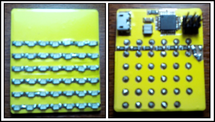
Programming Microcontroller
42 Leds are controlled by seven pins and I writted some functions for display text in the Leds matrix.
#include "ascii_75.c"

#define ROWS 7
#define COLS 6

#ifndef COLS
#define COLS ROWS-1
#endif

int led_array[ROWS] = {5,6,7,8,9,10,11};

void setup() {
  for(char i=0; i<ROWS; i++)
    pinMode(led_array[i], INPUT);
}

void loop() {
  printText("AndresMoreno ", 200);
  moveText("carlosandres_1409@hotmail.com   ", 80);
}

void setXY(char x, char y, long t){
  if(x > COLS-1)
    return;
  if(y > ROWS-1)
    return;

  if(x >= y) x++;

  pinMode(led_array[x], OUTPUT);
  pinMode(led_array[y], OUTPUT);

  digitalWrite(led_array[x], HIGH);
  digitalWrite(led_array[y], LOW);

  delayMicroseconds(t);

  pinMode(led_array[x], INPUT);
  pinMode(led_array[y], INPUT);
}

void setLine(char col, char line){
  for(char i=0; i<ROWS; i++)
    if((line>>i) & 0x01)
      setXY(col, i, 50);
}

void putChar(char c, long t) {
  long t0 = millis();
  while(millis()-t0 < t){
    for(int j=0; j<5; j++) {
      byte line = font[c][j];
      setLine(j, line);
    }
  }
}

void printText(char *text, long t){
  while(*text != 0) {
    putChar(*text, t);
    text++;
  }
}

void moveText(char *text, long t){
  char matrix[COLS];
  for(char i=0; i<COLS; i++)
    matrix[i] = 0x00;

  while(*text != 0) {
    for(char i=0; i<6; i++) {
      long t0 = millis();
      while(millis()-t0 < t) {
        for(char j=0; j<COLS; j++)
          setLine(j, matrix[j]);
      }
      for(char k=0; k= 5)  matrix[COLS-1] = 0;
      else        matrix[COLS-1] = font[*text][i];
    }
    text++;
  }
}
Working
On next video you can see the working of Charlieplexing for controll 42 Leds by 7 pins.