This assignment is focused on the converting the CAD drawing into the real-life objects. Yeah, it's time for machining. The Computer Numeric Control machine (CNC) is the machine which takes the input of design files and the machinable material like wood, wax, acrylic, composites, the output will be the fully designed files which can be assembled to make the usable products.
In this assignment it's time to make something which is life size and can be used by myself in my day to day activities. I was thinking about the things that I simply make which can be usable in day-to-day life.
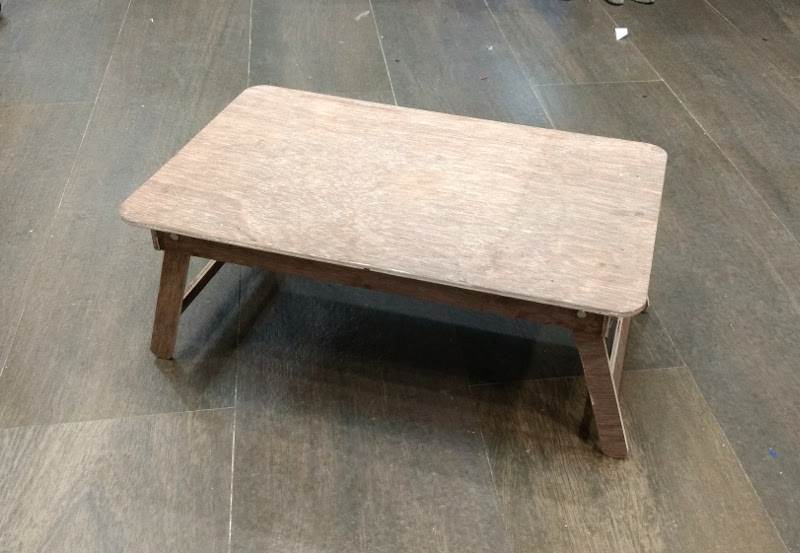
I do like to have a multi-purpose table which can be used for dining, using laptop or simple as a writing table. In dining method I do like Japanese style dining table which are not high and those doesn't need chairs to dine, and this kinda table allows one to sit cross legged which has it's own advantages over using chairs. As well as if I make this kinda of personal dining table that can be also useful for using laptop without burning your laps, this is also a healthy habit.
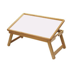
So, why not to go for it? For the reference I Googled the images for the laptop table, and found out design which suits my need. In the picture you will observe the table top can be tilted, but I thought of removing that feature.
Goal
The goal of this week's assignment will be making a table, and machining it using the Shopbot a large format CNC machine.
Designing
While designing pen-and-paper is your best friend grab them and start thinking. I drew the following diagram on paper which helped me a lot while drafting the same on the computer. It's really ease for me and I think for everybody to finalize your concept on paper and then proceed towards the software.
Step 1: Sketch it
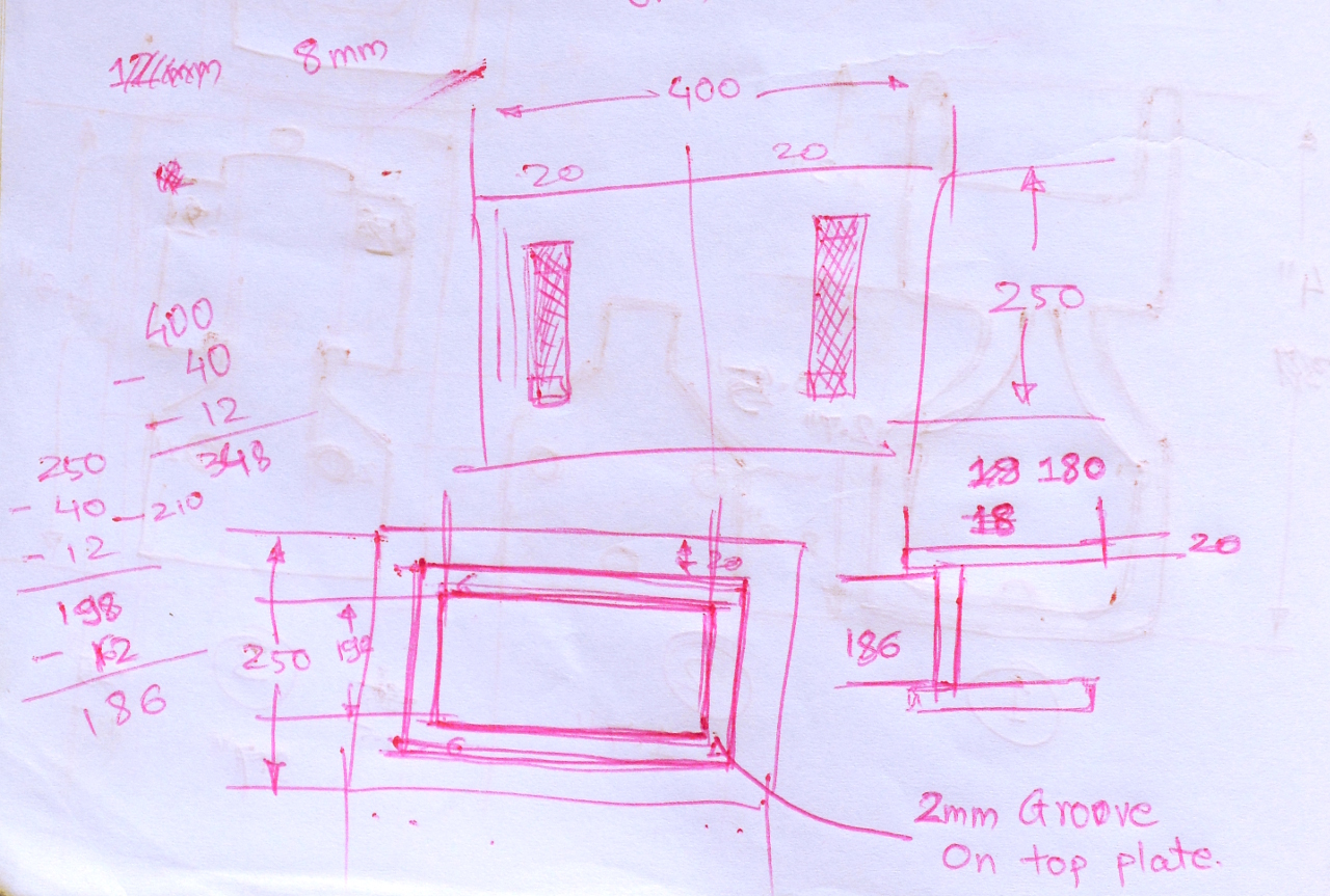
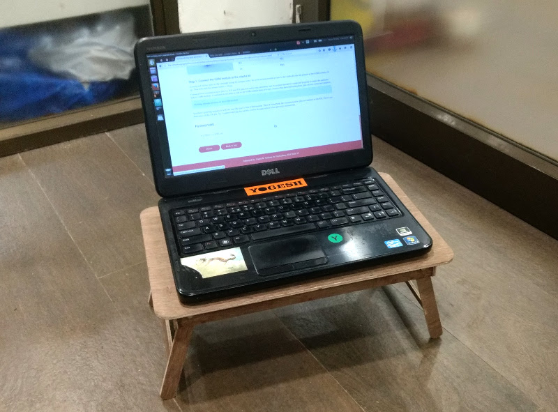
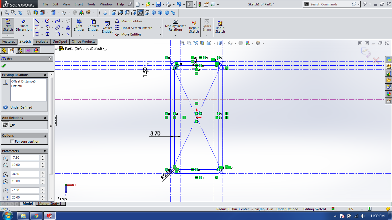
I've started thought process with the laptop table in mind. I started with measuring the dimensions of my laptop which turned out to be 342x244x32 mm. I've added little mount of place at surrounding on top face.
I've tried depicting all the dimensions as much as I can in the picture attached. Which includes pocketing and cutting the wood. I decided to use the 6mm thick plywood which is quite enough to take the weight of my laptop.
Step 2: Drafting it on SolidWorks
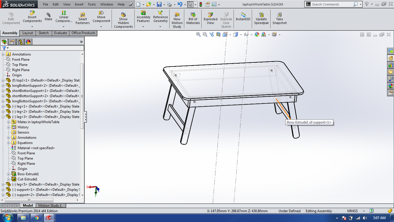
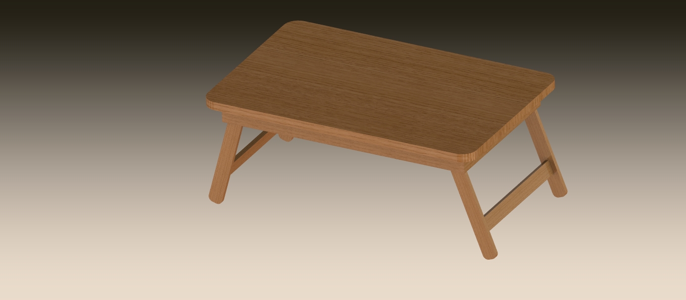
Solid work is a nice software which allows us to generate renders as well as it allows to make the assembly of the parts designed. Assembling of parts helps me to understand what can go wrong while making it into real world. And if any corrections required that can be done right on the software at the time of assembly.
Step 3: Exporting files - DXF format
Here for the designing purpose I've used the SolidWorks with make the 3D model. It's time to make it 2D which can be used by most of the machine softwares. Also, when you have DXF files which can be opened in the software for further modifications if required.
Step 4: Scale it and make it using the cardboard
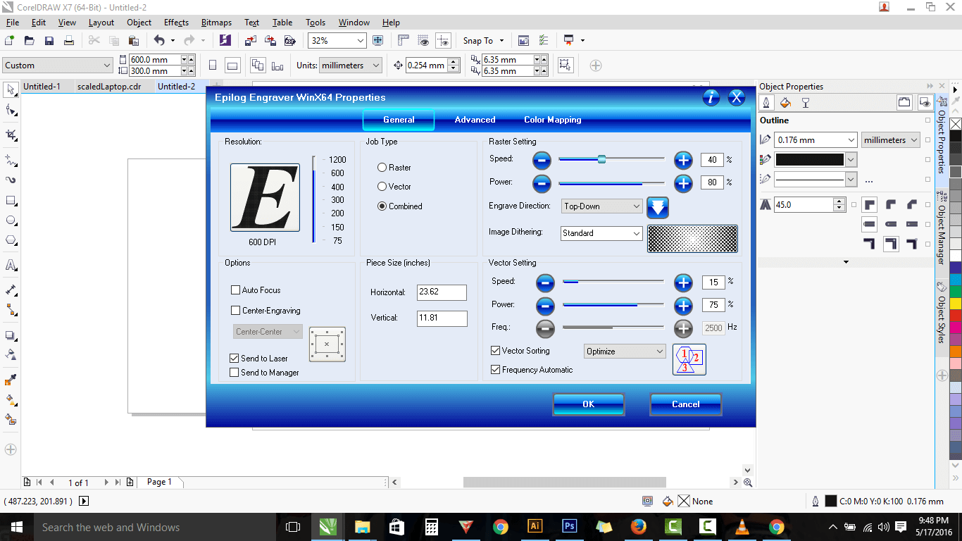
Even when you assemble using the software in virtual world it's always better to make the scale model of the thing that you are intended to make. I've open the exported DXF files using the Corel Draw to scale them down. Scaling down allowed me to use the laser cutter for machining. I made a scale model of the table using cardboard.
Step 5: Stick them together to make scale Model
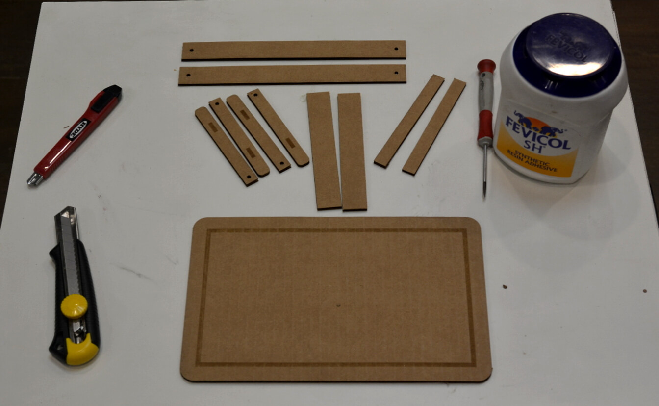
Once I got them cut, I glued them together. The glue I used was the Fevicol. Fevicol is an white synthetic adhesive used by carpenters to stick pieces of woods. Here in the photo you can see the engraved portion which is the grove which will support the assembly structure, in actual design it is of depth 2mm.
Step 5: Generating tool-path using VCarvePro
VCarve Pro V8.0 ShopBot Edition provides a powerful but intuitive software solution for cutting parts on a ShopBot CNC Router. There are tools for 2D design and calculation of 2D and 2.5D toolpaths and along with the ability to import and toolpath a single 3D model (STL, OBJ etc.).
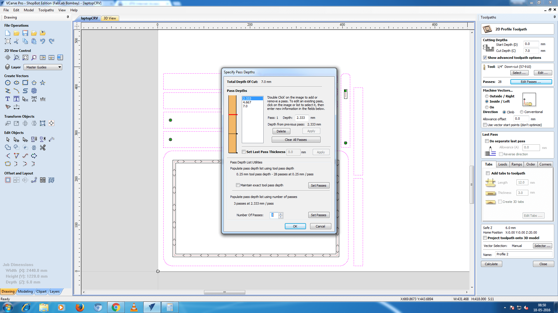
Tool path generation is the major task in the computer aided machining. Tool-path is nothing but as name suggests, it tells the machine how tool should move to do the job perfectly. As my batchmate Akshay Goharkar always says "Tools don't have brain use your own", that I realized here. So, for every part in our design we have to mention
- what the tool should do?
- How much time it should pass to cut the object without breaking tool?
- What is the tool size?
- What is 2D profile and what is and what is pocket?
Observer the pictures attached below
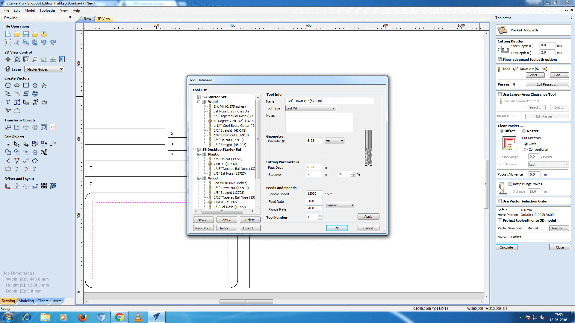
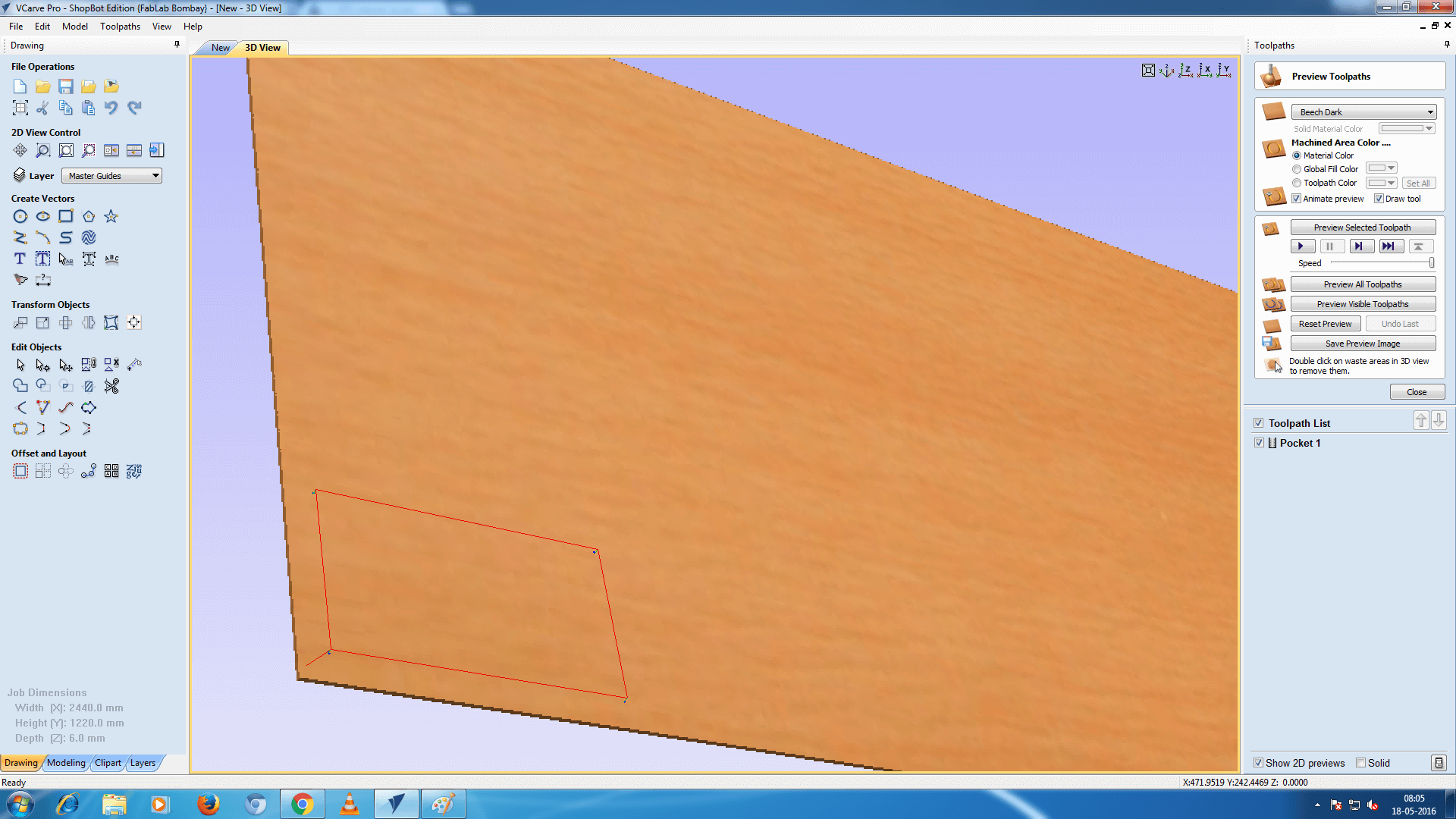
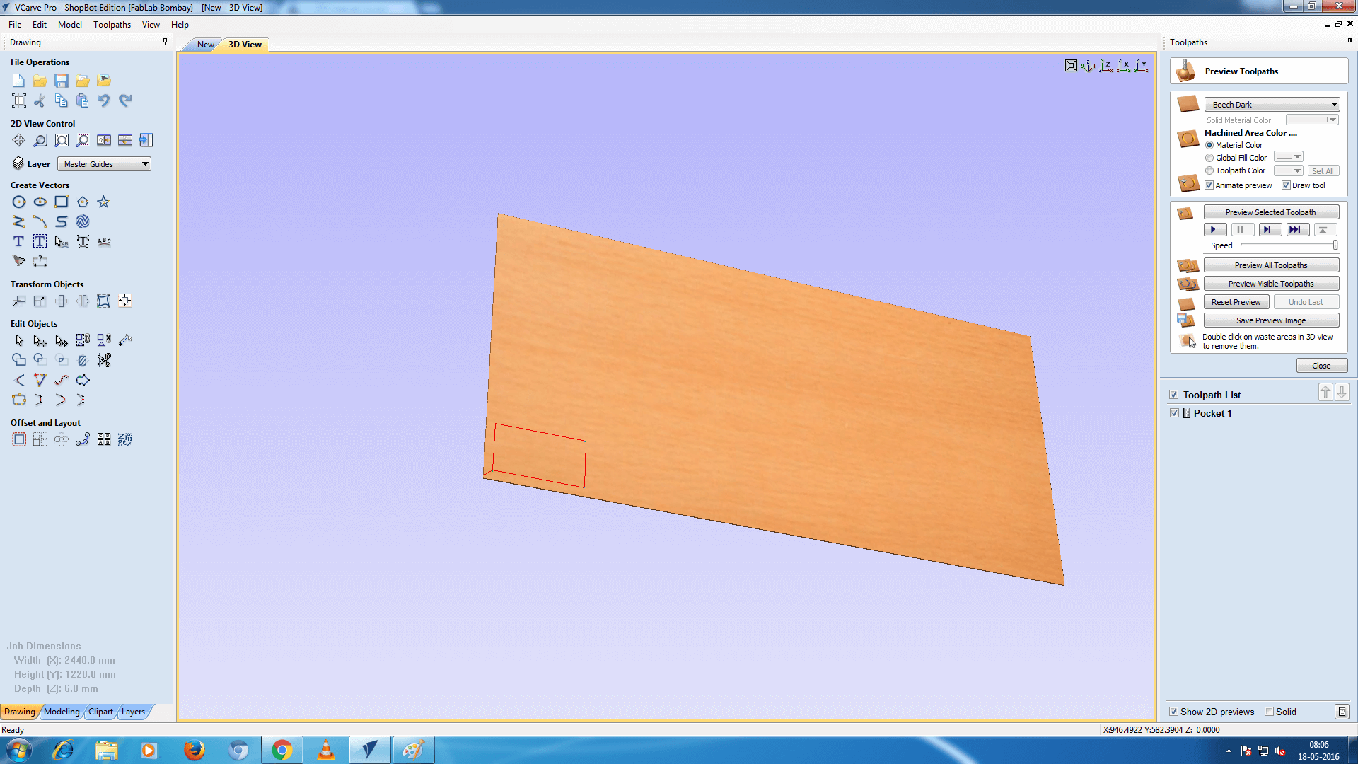
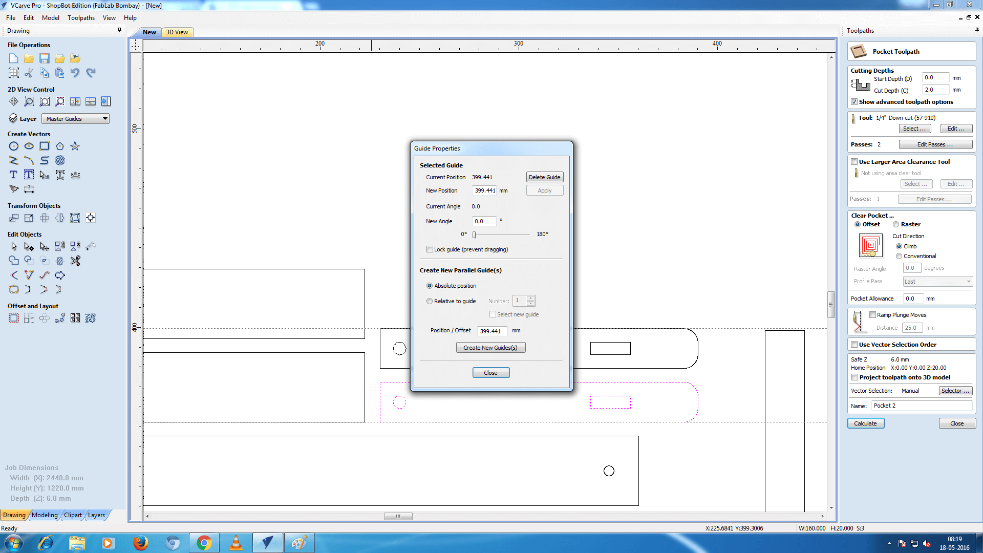
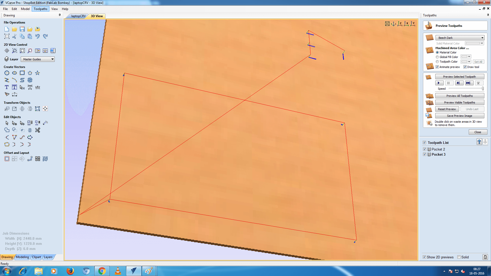
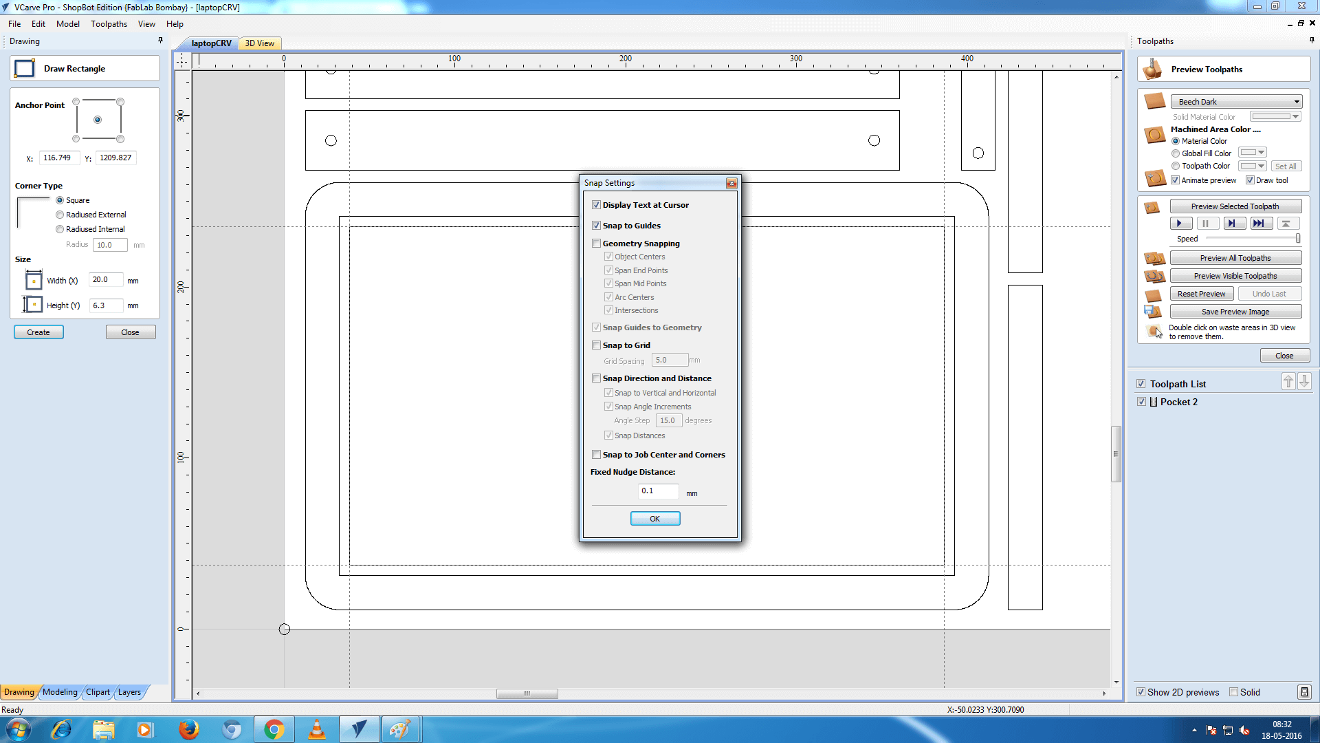
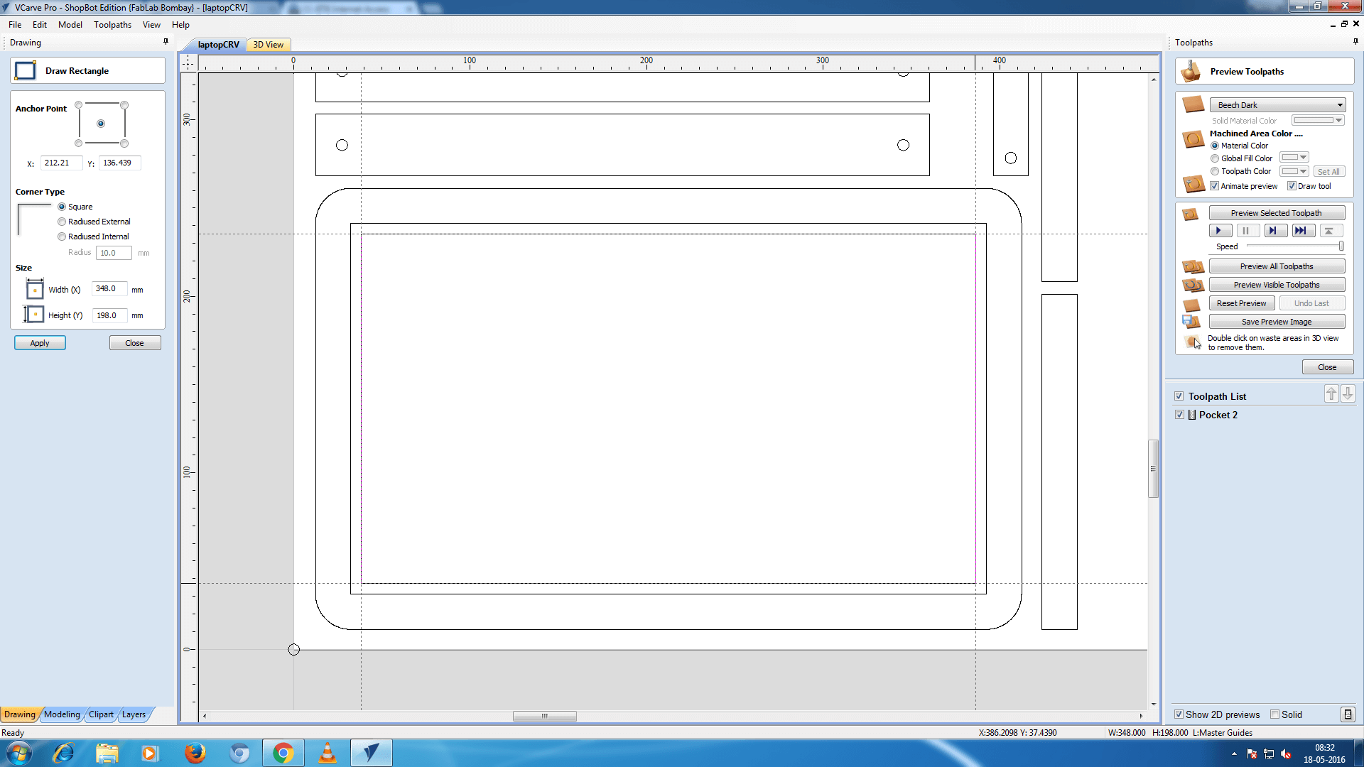
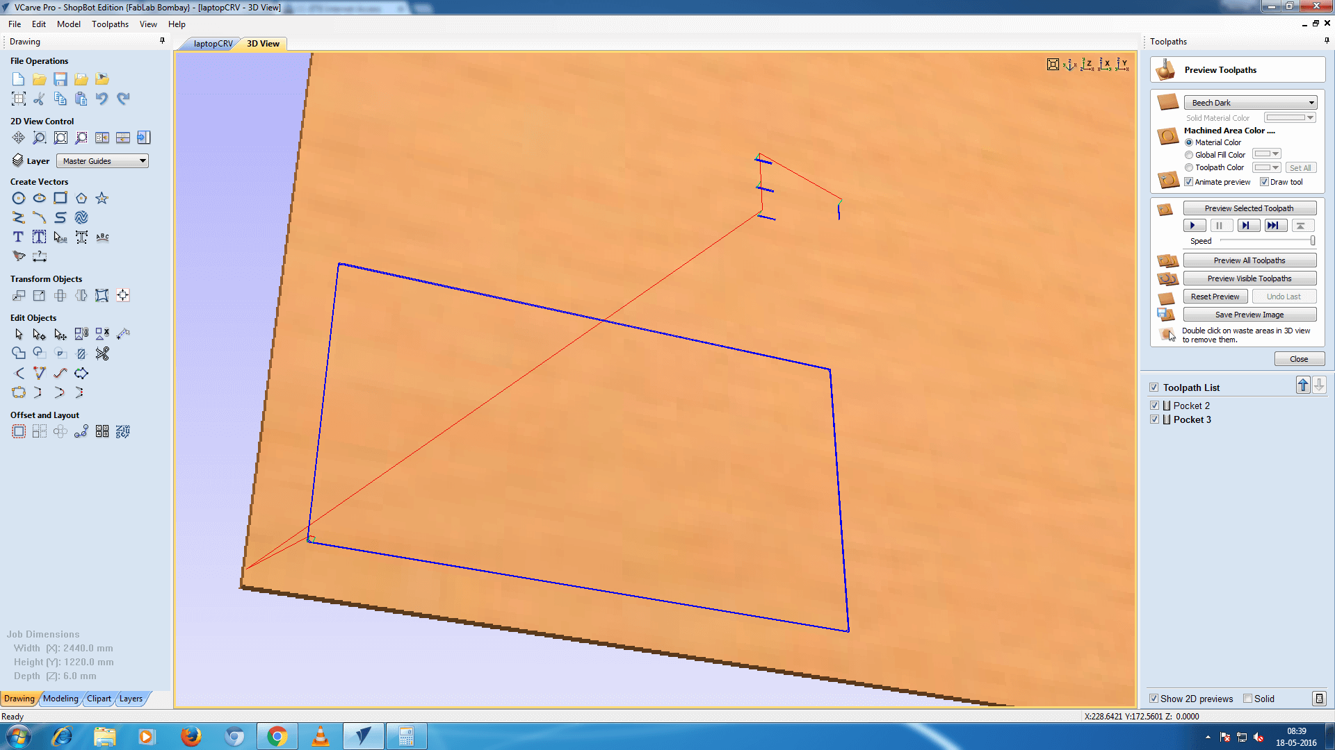
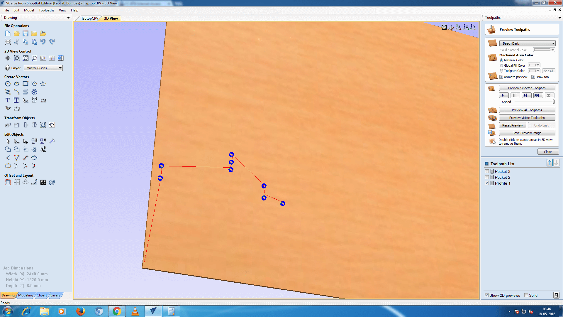
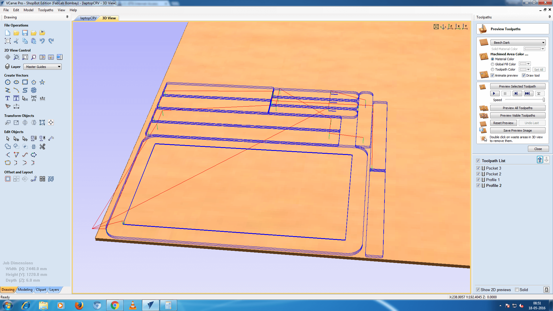
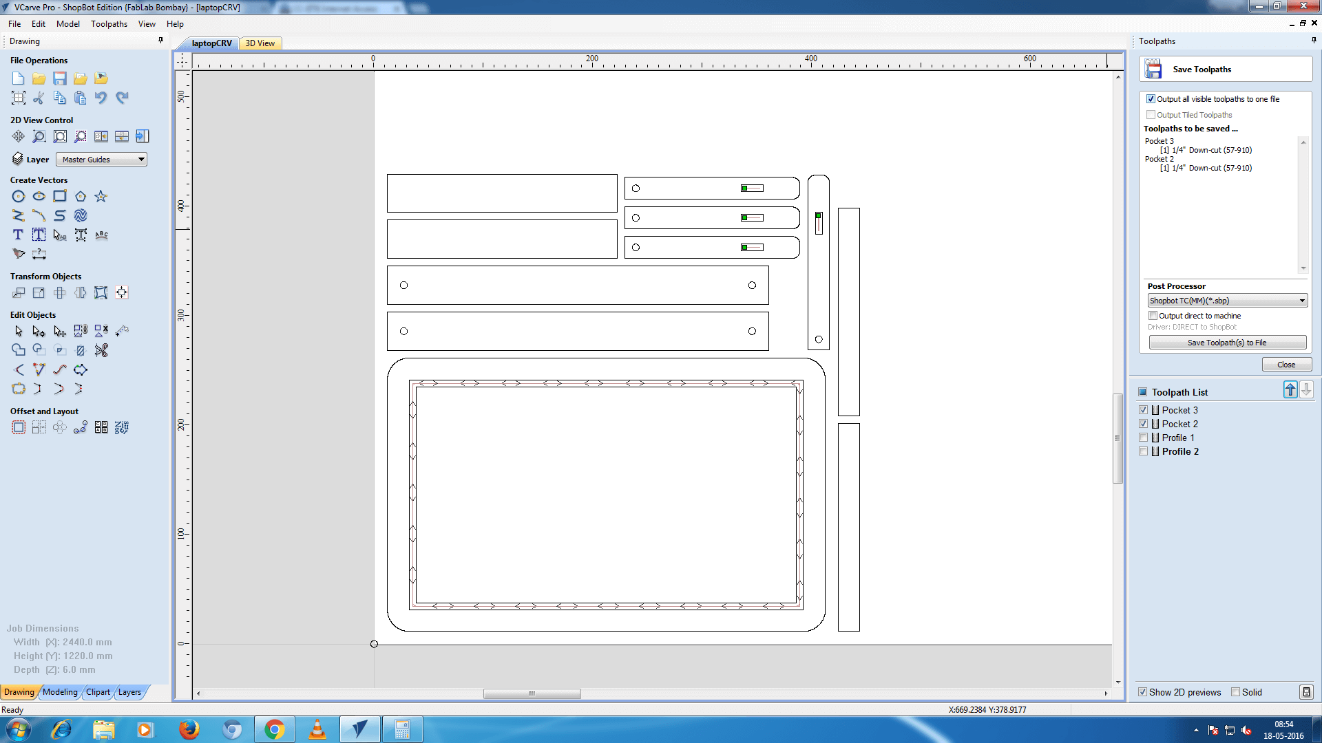
You can see two different views there in the screen-shots. One shows the 2D design and one 3D. The 2D view shows the line drawing where I selected the different paths and contours to be as pocket and to have 2D profile.
- Pocket => Engraving
- 2D profile => Cutting
Once we are done with the tool-path and tool-selection it's time to export shopbot file which has extension .sbp. This file we can import in shopbot software with which we can machine the material loaded.
Step 6: Let it roll!
Now load the tool that you have generated tool-path for. I've used 6mm tool, this tool allows me to set wide range of feed rate and the spindle speeds. When using thicker bit it doesn't makes the speed and feed rate combination less stringent.
Step 7: Lights, camera and Action
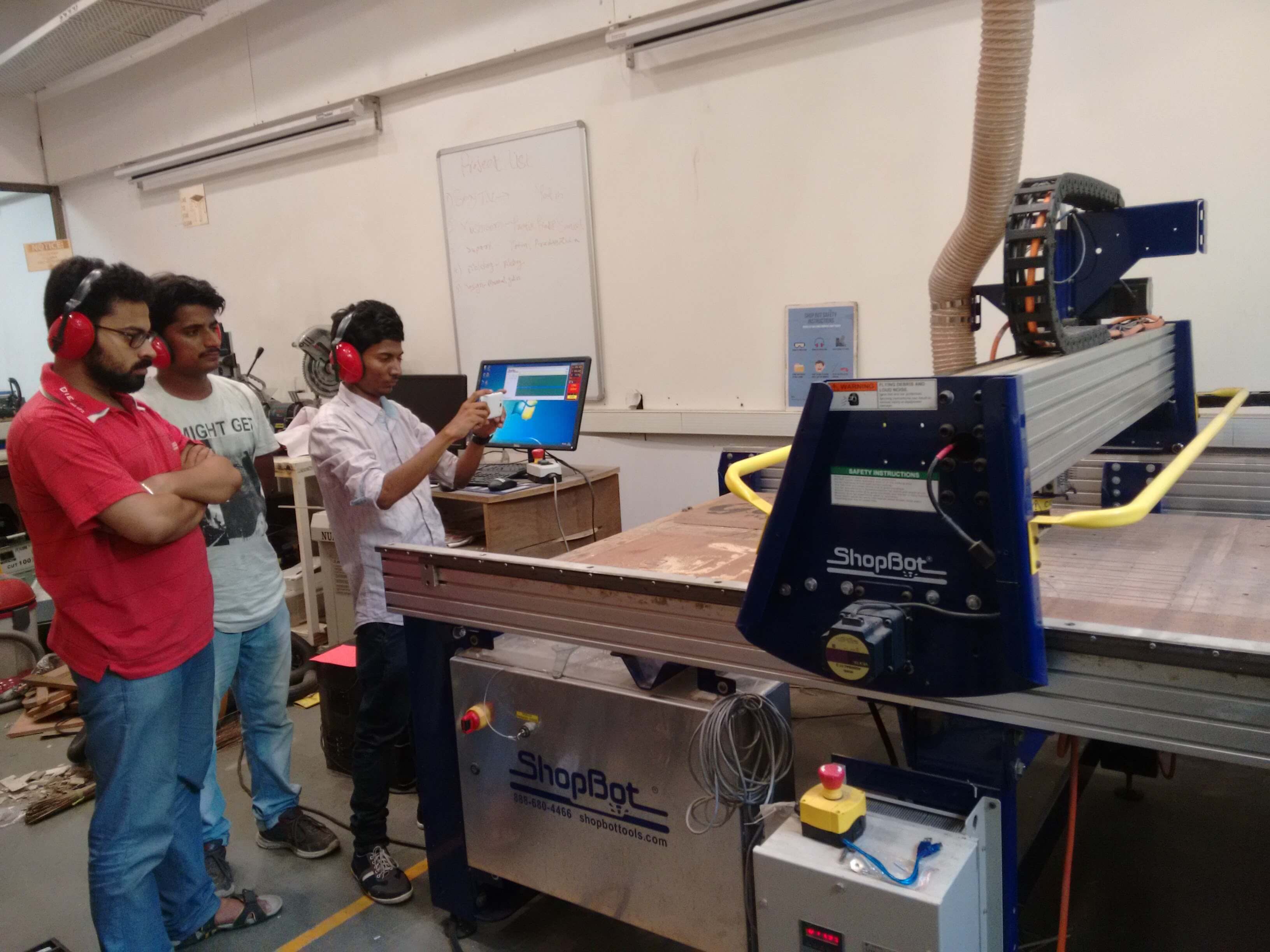
Feeling very sorry for not using the safety/protective goggles.
How to?
How to change tool?
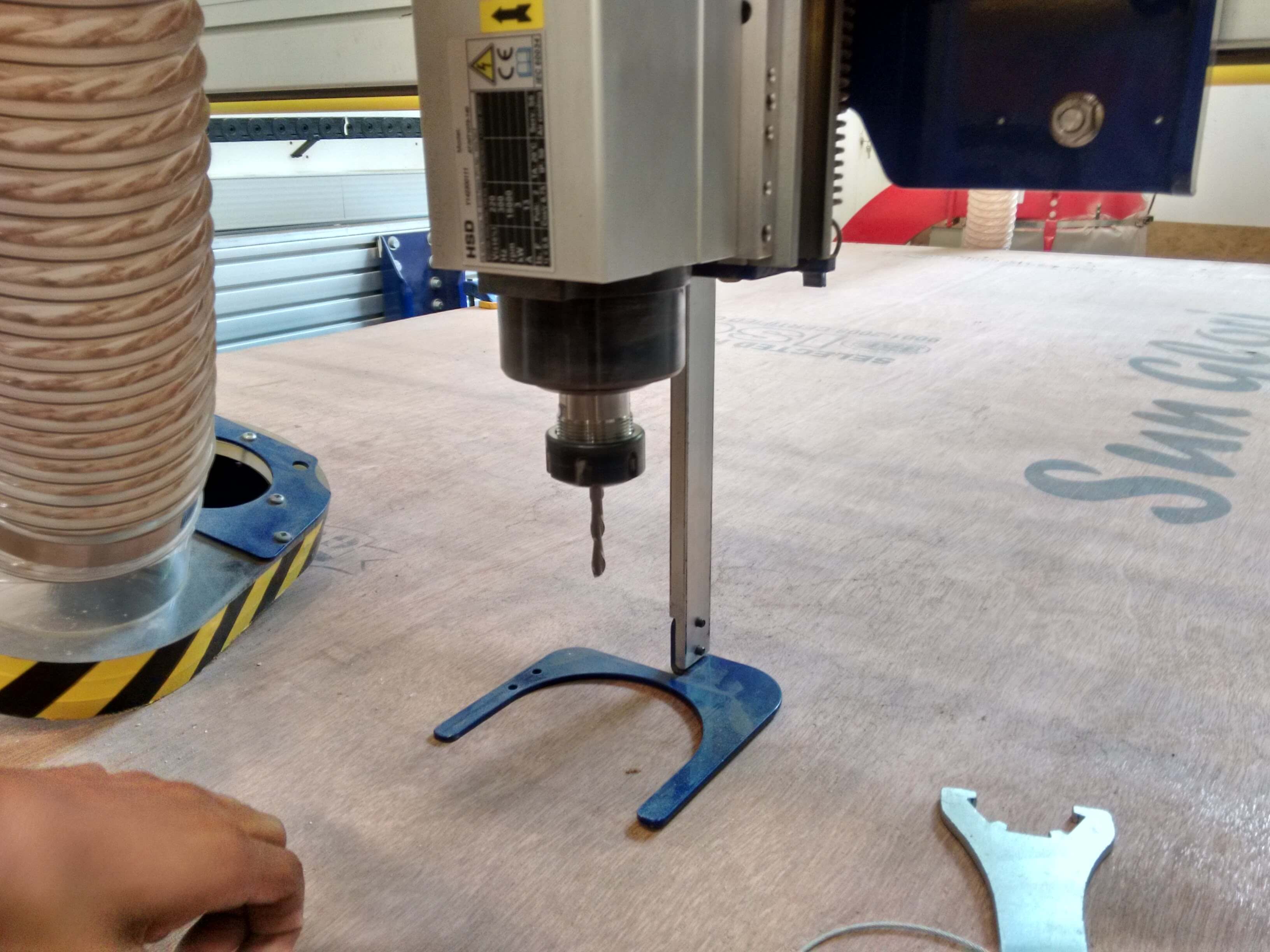
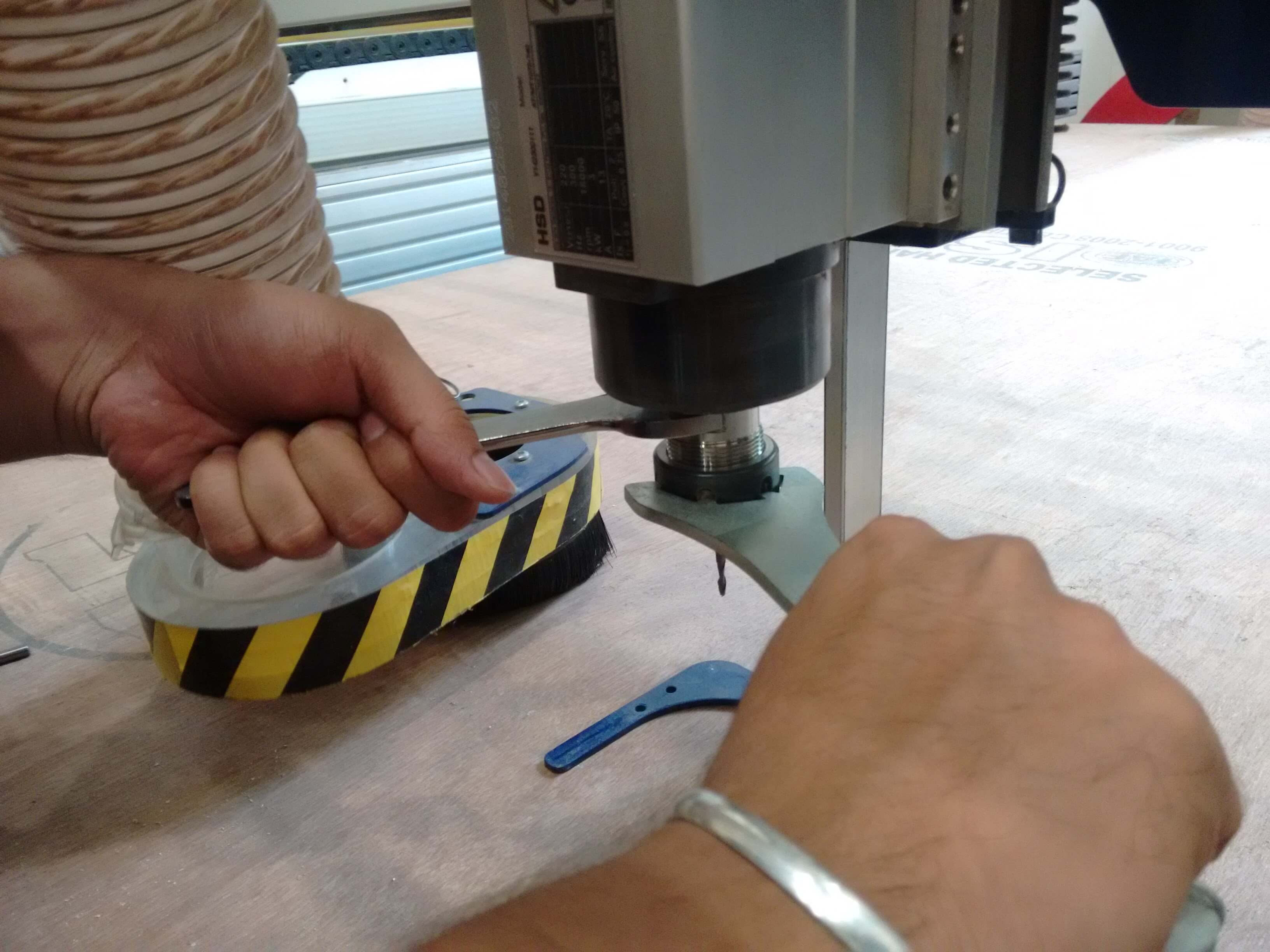
- Remove dust collector hose
- Access the tool rack and get the appropriate tool
- Get the tool changing spanner
- Loose the tool holder by rotating both the spanners in inward direction and remove the tool
- Load the appropriate tool, use spanners to tight but this time move them outward to tight it
Adjusting Z zero
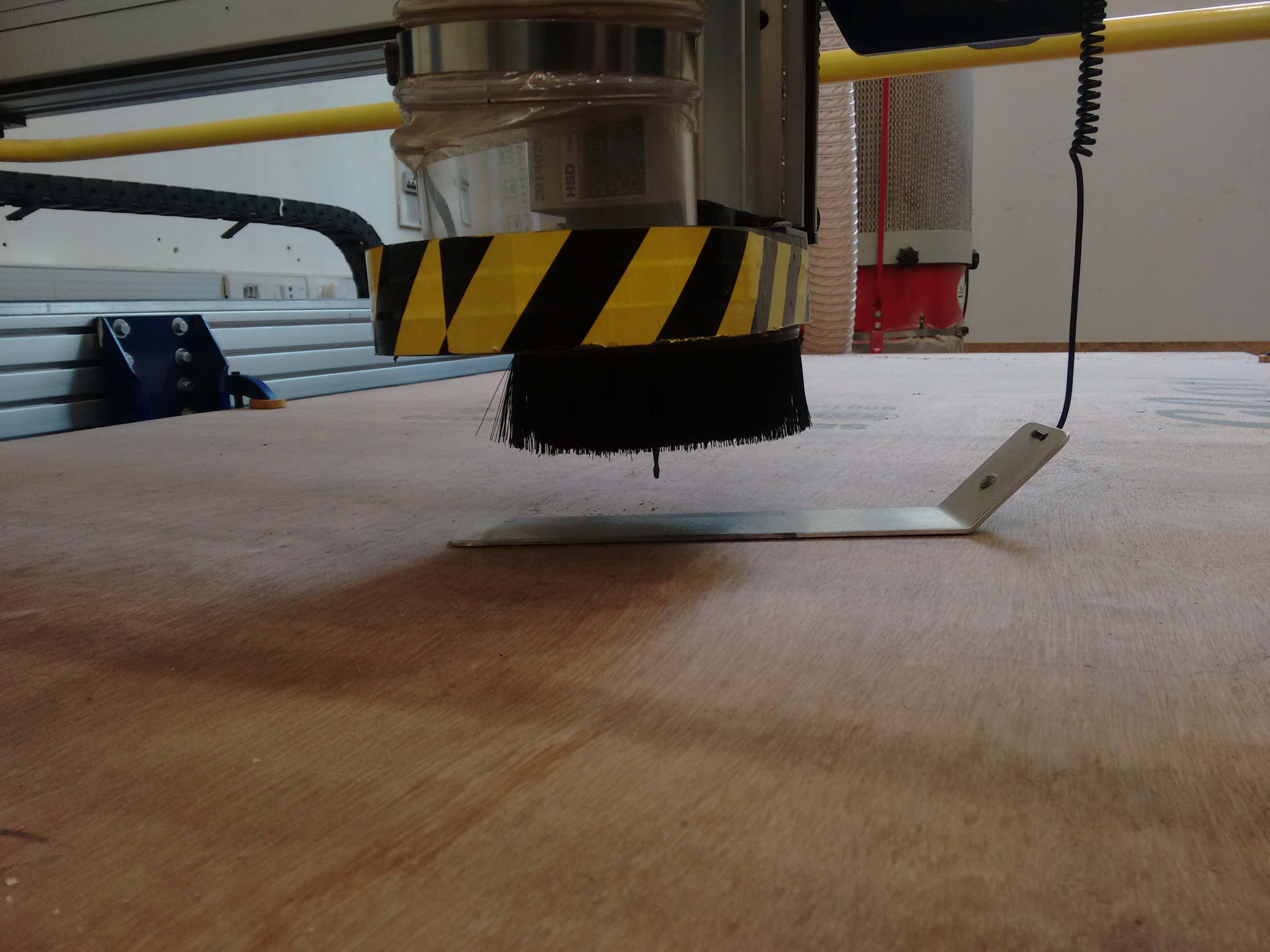
Zeroing Z is very important activity that one should do. Doing this make the machine aware that what's the position of the tool with respect to material thickness and how much depth it has to reach for cutting/engraving. When you give command for zeroing the Z, software asks to keep the metal plate which is located at the spindle right below the tool, after this software makes the tool to go and touch the plate below and goes up 1 inch and stays there.
Basically the plate we kept below the tool is connected to the shopbot using the wire which somehow manages to identify the touch of tool and provides feedback to the software.
Hero shots